engines
-
Posts
57 -
Joined
-
Last visited
Content Type
Profiles
Forums
Events
Everything posted by engines
-
I'm opening up the first production run from 10 to 30. Please join the discord if you're interested in getting hold of one of the last couple of unallocated units. https://discord.com/invite/YExFSJrB
-
All the sheet metal arrived for the quadrant assemblies. Dimensional accuracy less than 0.5mm, which is within tolerance.
-
Try this one: https://discord.gg/aB9Qu4q2gG
-
The first 10 units have been provisionally allocated. I've started a reserve list in case anyone drops out. Join the discord group if you want to sign up: https://discord.gg/GKZAWQRnPK (this link is good for 50 people).
-
I've sent you a DM.
-
I mean, I could have finished it a year ago if I pulled my finger out. But I suspect you're referring to something else? Edit: Oh... making hardware for a module that may no longer be supported... Yeah, great timing.
-
Hello everyone, Sorry for the long silence, I've been busy and working through a couple of iterations of the design. I have been using the original version for about 2-3 years now and I have got enough use out of it to understand how I want to improve it. I am building a batch of ten units now, they may take a little while, but I'm targeting the summer for completion. The first three of those ten will be sold at cost on a first-come, first-served basis, then the remaining 7 will be a pre-production discount. If there's enough interest after that, I'll do a larger production run, but for now I expect it'll only be these 10. The initial three are notionally assigned subject to taking payment. If anyone is interested in getting on the list, please DM me.

-
 Harrier HUD rocket symbology slant range begins winding down at ~6,000' and continues to the next (10:30 o'clock) index at ~5,000' which are the slant ranges used by the gun symbology. Actual ranges should be: 12:00 o'clock - 10,000' 10:30 o'clock - 9,000' 9:00 o'clock - 8,000' 6:00 o'clock - 6,000' 3:00 o'clock - 4,000' 12:00 o'clock - 2,000' https://clipchamp.com/watch/js4bhiyQw1V?utm_source=share&utm_medium=social&utm_campaign=watch
- 1 reply
-
- 2
-

-
This bug is still in effect.
-
Hey, version two design got underway but then was put on hold due to work and personal commitments. I'm hoping to get back into it very soon.
-
I've checked this again after discussing on the Razbam discord and found that the issue was related to the pedal setup. When the input device was removed, the trim worked as expected.
-
It's for the gains...
-
The RCALL page drops leading zeros of the 5-digit groups, i.e. AB1234501234 is presenting as AB123451234. Can't yet confirm if this happens with just the second group, or if it applies to the first, too, or if the CAS page has the same issue.
-
Here's a quick update with the modified Thrust Master F/A-18 stick grip. I've attached the insert ring .stl file I used to set the trim switch in the SSS location. For the SSS location, the hole was opened up to 20mm with a step drill, deburred, and a notch filed in for the keyway. And this is what it looks like when set up with the throttle. Trim_Ring.stl
-
Video: https://www.dropbox.com/s/3w20af70gzmgkt9/Rudder Trim Bug.mkv?dl=0 Track: https://www.dropbox.com/s/7a6ztzcwfxpurb1/Rudder Trim Bug Track.trk?dl=0 On the ground, aircraft powered up and configured for take off, rudder trim behaviour is as expected. I.e. when either rudder trim: - switch is clicked with mouse, - default keybindings are pressed, or - bound jostick switch is used The rudder trim gauge moves in the correct direction, the pilots feet and pedals move in the correct direction, and the rudder control surface moves in the correct directions. When the aircraft is airborne and configured for flight, none of the above actions result in any rudder control deflection or indication. Rudder Trim Bug Track.trk
-
Here it is in action when getting back on the boat:
-
Not sure exactly, but I would guess high hundreds at least.
-
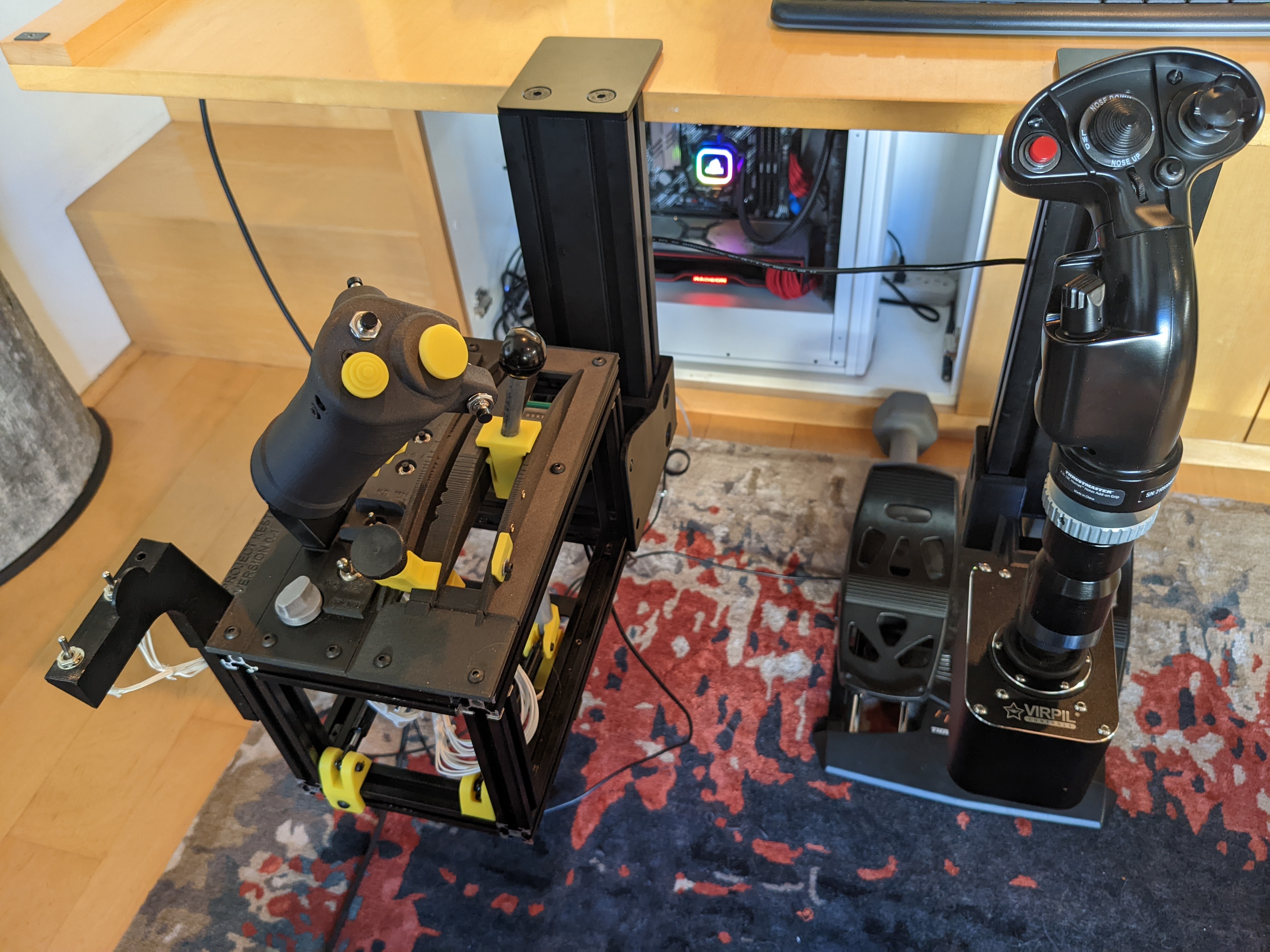
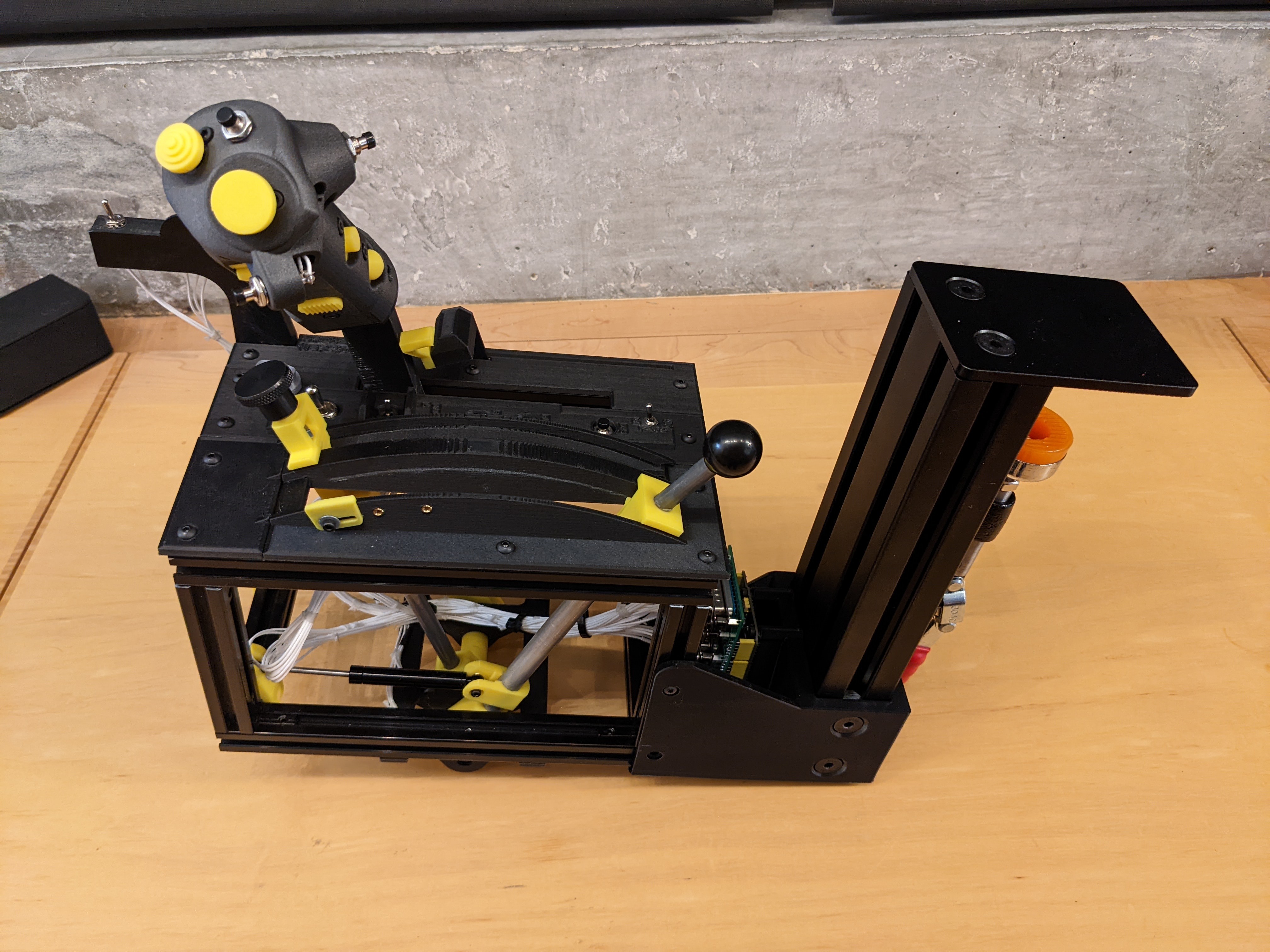
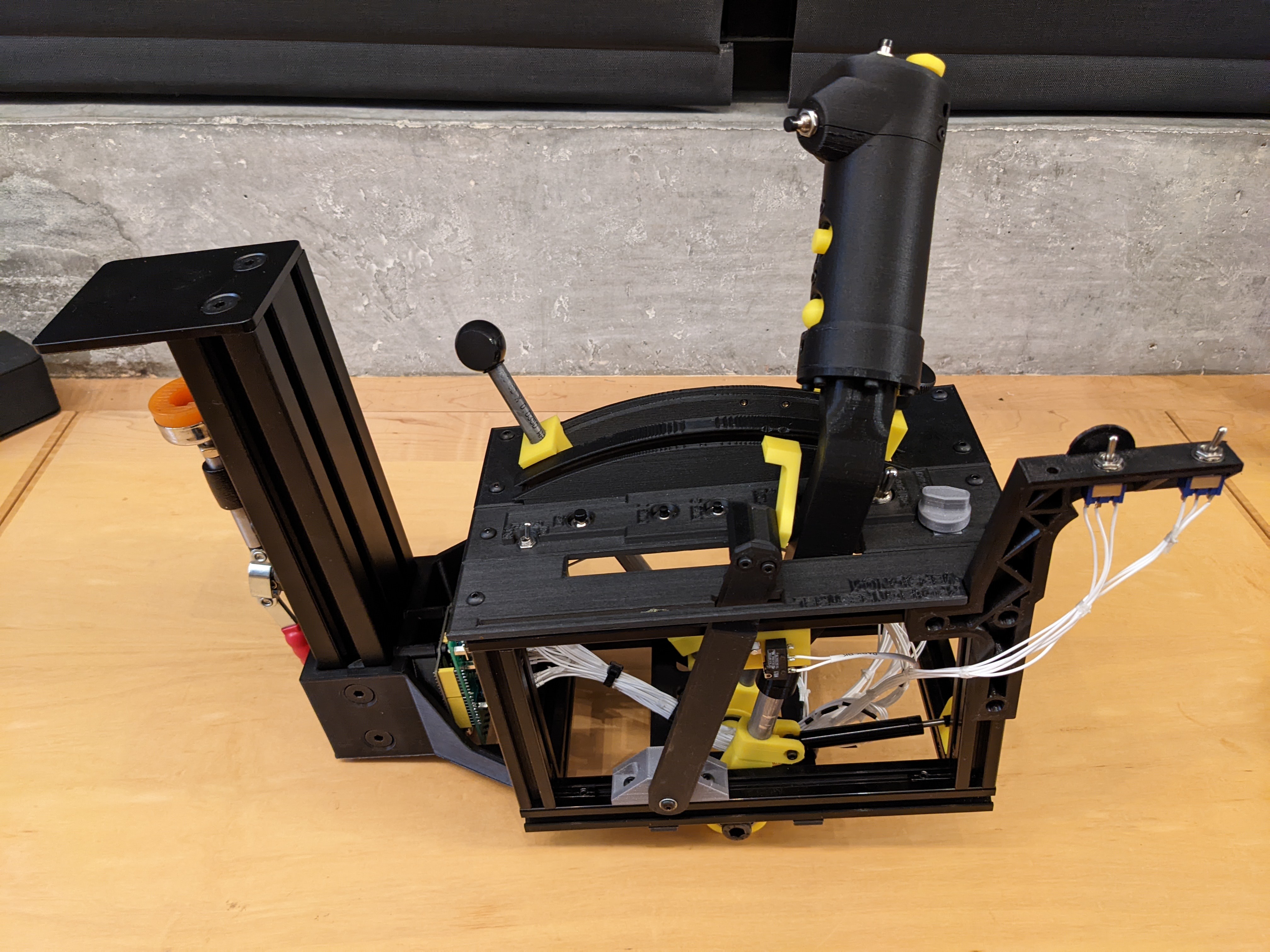
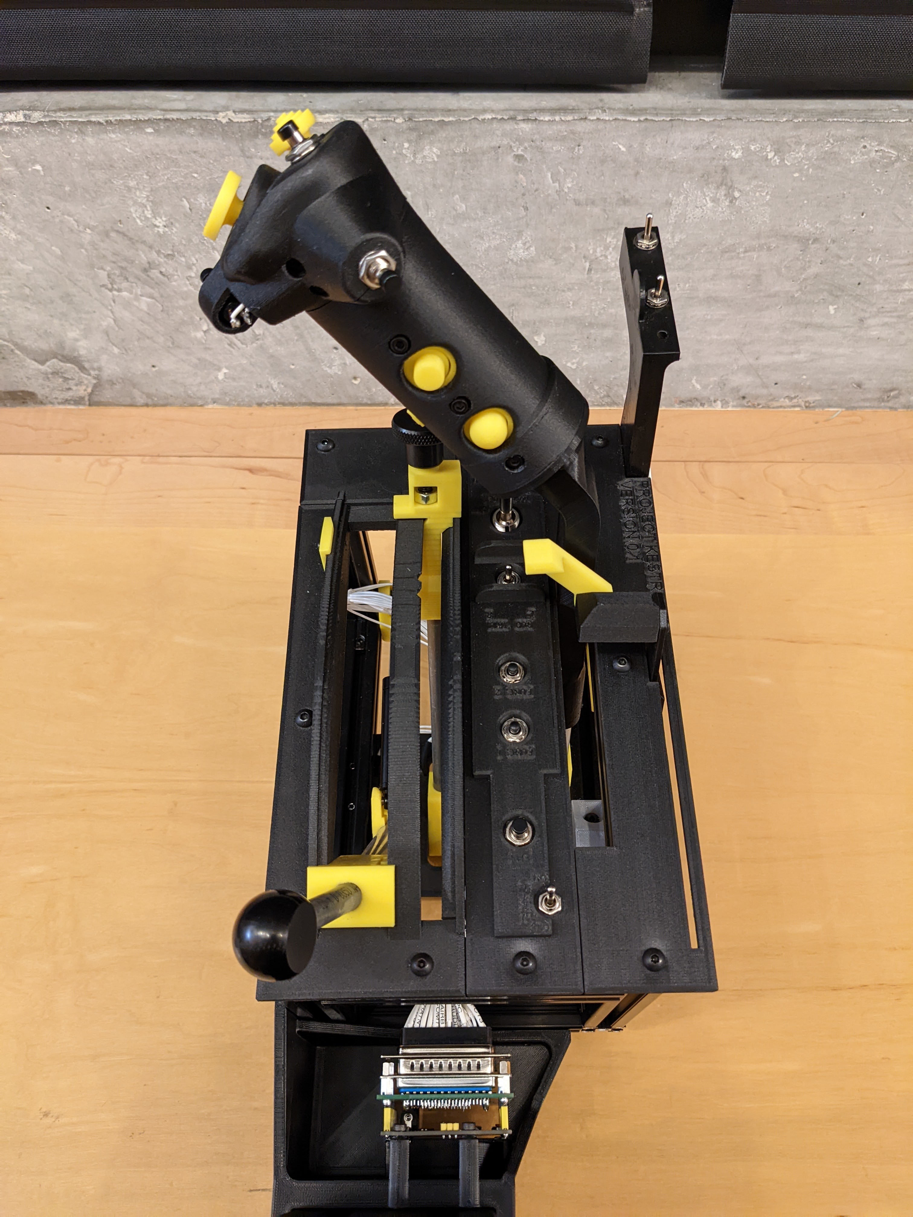
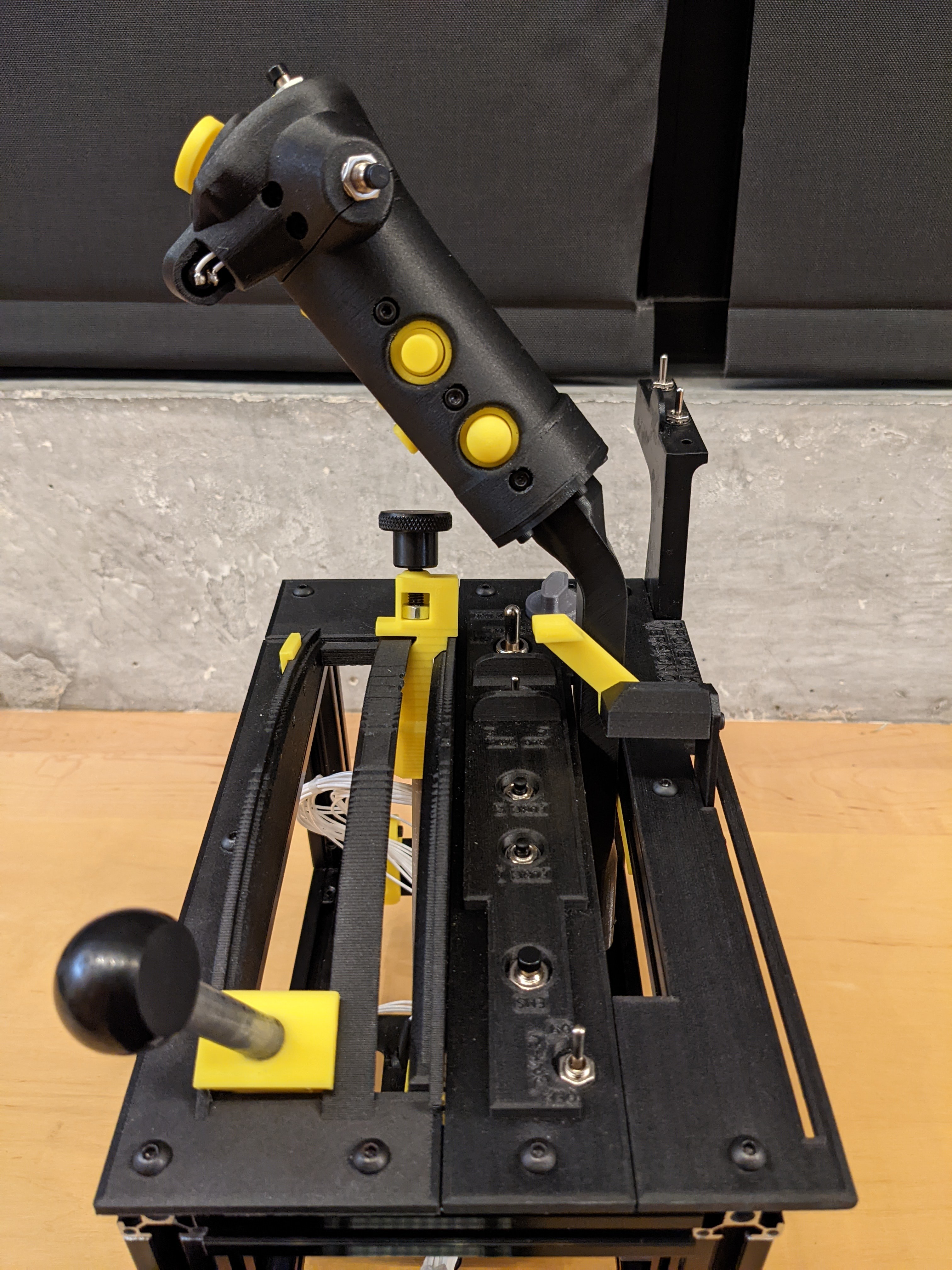
Quick photo dump! About 100 hours of use and most of the kinks are ironed out. More to do.
-
I started working on the final wiring, which involved changing all the wires from the 2mm JST connectors to DSUB terminals to fit onto the Arduino shield I designed. Unfortunately I noticed that I messed up the PCB design, so I have to re-do the shield.
-
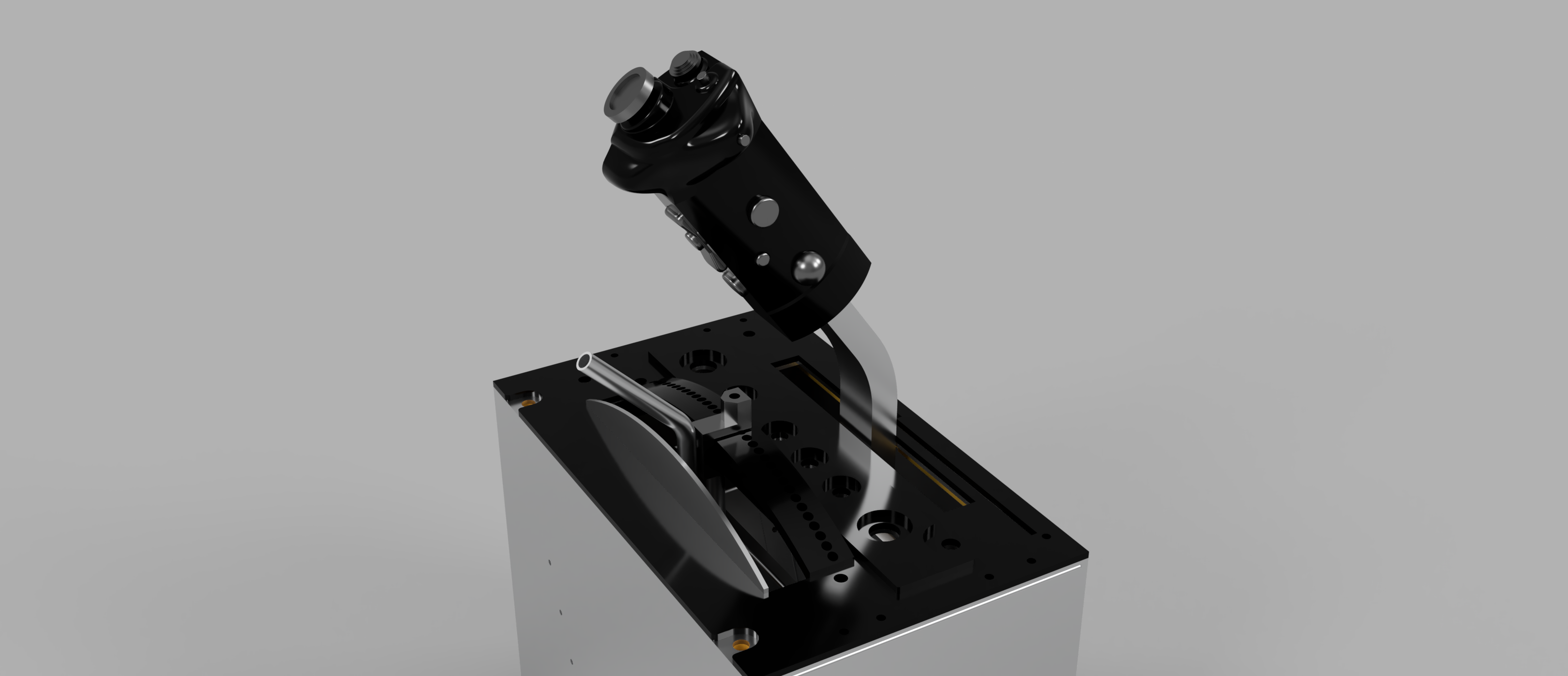
Here it is in DCS for the first time, just testing the axis and parking brake:
-
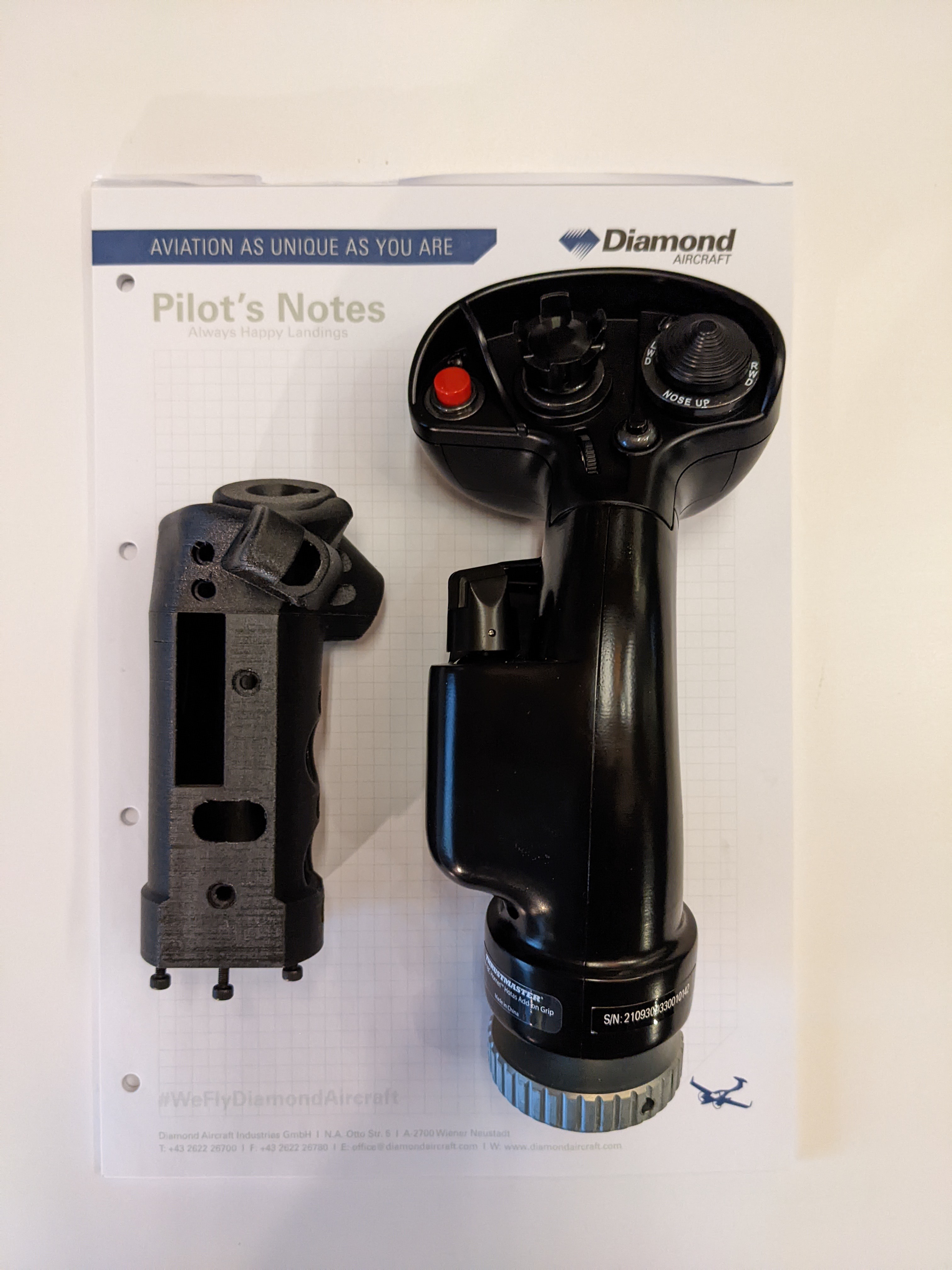
This is mine versus the grip above. The one from the real aircraft below.
-
That would be great. I'm based Pacific Northwest and won't bein the UK until May based on my current plans. If you can get a couple of measurements like the total length or diameter, that'll be enough to get me in the right ball park.
-
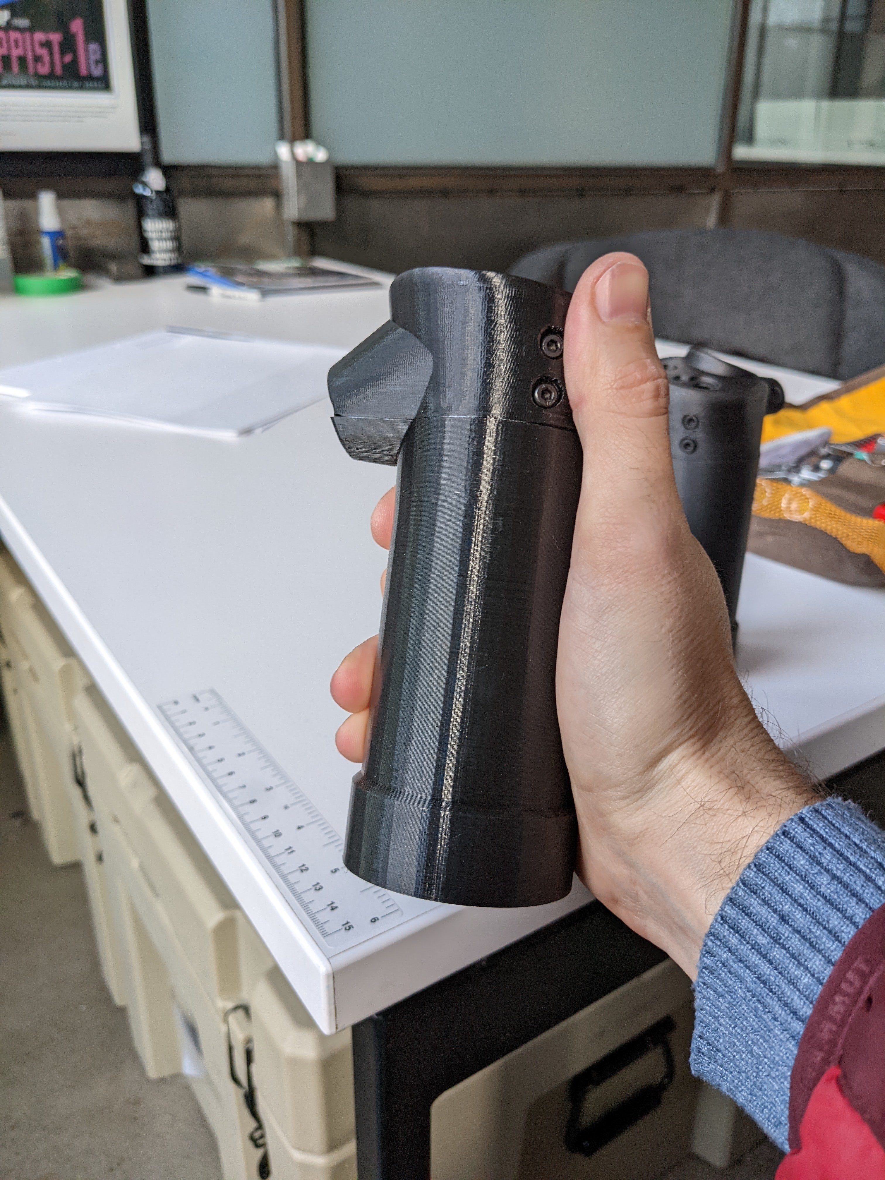
When I scaled the drawings for the grip, I made the assumption that my reference drawings had a thread size of 1.5" at the base of the grip. The resulting grip always felt a bit too large. It turns out, from a ln obscure reference someone dug up with drawings of a training simulator, that thread was 1.25" meaning my part was oversized by 20%. Having corrected for this, the new grip feels closer to what I was expecting (noting my only real reference is from an other jet type I've worked on). If anyone here has sat in either a real Harrier GR7/9/9a, AV8B, or their respective simulators, can you tell if the lower photo looks right?