Bestandskraft
-
Posts
154 -
Joined
-
Last visited
Content Type
Profiles
Forums
Events
Everything posted by Bestandskraft
-
Now that the manual is out we can safely say that there will be neither paraflares nor NVGs initially (at least neither are mentioned). Any suggestions on how to use the F-4E for night A-G combat except script/AI-generated flares or a wingman flying a different aircraft type dropping them?
-
To elaborate a bit, since it is unlikely we’ll get NVGs at least initially and since the Pave Spike is day only, without illumination flares we won’t be able to use the early F-4E in night air-to-ground combat organically (at least I cannot see how at this point). I doubt most online servers will have provisions for script generated flares.
-
Since I haven't found anything on the forums or Discord: Will the Heatblur F-4E come with the option to equip SUU-25 for carrying and releasing LUU-2/B / MK 24 parachute flares and/or LUU-1/B, 5/B, 6B target markers?
-
Both the "Emergency jettison button guard - CLOSE" and the "Emergency jettison button - OPEN" act as toggles in that pressing either will open the guard when closed and close the guard when open. Tested with 2.9.0.46801 in the CE and EE, not in the BE.
-
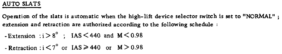
fixed internally Auto slats schedule may be incorrect
Bestandskraft replied to Bestandskraft's topic in Bugs and Problems
Just checked this behaviour in 2.9.0.46801 and the F1EE (did not test the other aircraft). The auto-slats now start extending at 7.3 AoA and start retracting at 6.8 AoA as indicated in the F2 view status bar, which seems equally incorrect with reference to the publicly available manuals. Could you verify the behaviour again please? -
fixed internally Auto slats schedule may be incorrect
Bestandskraft posted a topic in Bugs and Problems
According to both the F1ED and F1AZ flight manuals available on the net, the auto slats extend at i > 8° and retract at i < 7°. In the game, they extend and retract at 7°. Since I do not have the F1CE/EE's flight manual available, this might be correctly simulated, but in case there was an oversight I thought I'd mention it.
-
Has supersonic performance been adjusted?
Bestandskraft replied to Bremspropeller's topic in DCS: Mirage F1
Noticed the same discrepancies and did some tests of the RL F1ED optimum climb profiles (also contained in Aerges' manual): Unless I'm totally misunderstanding how to fly these profiles, the aircraft significantly overperforms in the high-altitude/high Mach regime. Results below. They pretty much match what Bremspropeller has already established, except that fuel consumption has been lower, not higher than IRL in my tests. Very close match with published data until 30,000 ft. Parameters to reach 50,000 ft, clean, standard day should be 465 USG, 120 nm, 8:00 min. Observed in DCS: 422 USG, 73 nm, 6:10 min. Parameters to reach 2.1 M, clean, standard day at 36,000 ft should be 465 USG, 99 nm, 6:30 min Observed in DCS: 440 USG, 70 nm, 6:00 min. 50k.trk accel.trk 50k.acmi accel.acmi
-
Mirage F1 pylon identification/data
Bestandskraft replied to Bestandskraft's topic in DCS: Mirage F1
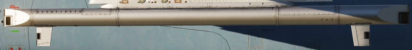
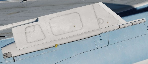
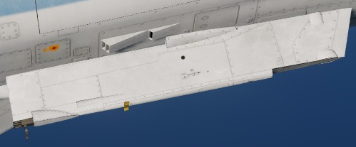
Thanks for your reply! Ad 2) The pylon does look similar to an LM14, but the aft edge of the pylon in-game is straight while the LM14's aft edge in your photo is slanted. The schematic from the Mirage III flight manual also looks as if the LM14 becomes narrower vertically in the aft-direction, which isn't the case in-game. The only picture of a centerline pylon that looks like the one in-game I have meanwhile found is the following (blue aircraft on the top-right-hand corner), but it doesn't provide its name: Ad 5) I had also found that list, but it seems the in-game pylons are actually weightless except for the CLB-4 which weighs 183 kg according to the applicable .luas I was able to find (Link). -
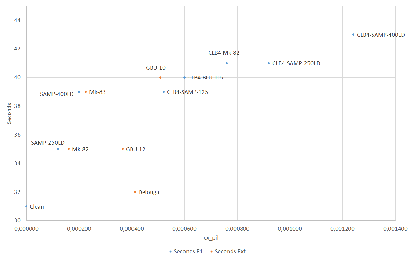
I have noticed what seem to be abnormalities in stores drag modelling for the F1. All empirical data for the following study were obtained in an F1EE with 10% fuel remaining, unlimited fuel selected, starting at 1000 ft MSL, 0.65 M, on a standard day, no wind. The study consisted in air starting the jet with MIL power already selected, then, upon entering the cockpit, immediately engaging AP in altitude hold mode and measuring the time until the jet reached 600 KIAS as per the F2 view. The jet was loaded only with the store given in the diagram on station 4, 0% gun, 30 Chaff, 15 Flares. The cx_pil values were obtained as per the following table: Store cx_pil Loadout URL Belouga 0,000413 Link CLB4-BLU-107 0,0006 X Link CLB4-Mk-82 0,00076 X Link CLB4-SAMP-125 0,00052 X Link CLB4-SAMP-250LD 0,00092 X Link CLB4-SAMP-400LD 0,00124 X Link GBU-10 0,000508 Link GBU-12 0,000365 Link Mk-82 0,00016 Link Mk-83 0,000225 Link SAMP-250LD 0,00012 X Link SAMP-400LD 0,0002 X Link Clean 0 Results Interpretation All stores with an "X" in the Loadout column above have a cx_pil defined in the /_G/launcher/ folder of the datamine. The cx_pil from other stores had to be obtained from other places (see respective link). Stores with a cx_pil in the Loadout folder (blue in diagram) seem to follow a certain logic in that a higher cx_pil causes a longer time for the aircraft to reach the target speed. Notable exceptions are the SAMP-400LD and the CLB4-SAMP-125 with cause the aircraft to reach the target speed in the same time span even though the cx_pil is significantly different. The same can be said when comparing the CLB4-Mk-82 and the CLB4-SAMP-250LB. Stores without a cx_pil in the Loadout folder (orange in diagram) do not seem to follow a discernible logic in that an increased cx_pil does not necessarily imply an increased time to reach the target speed. This is most notable with the GBU-12 and Belouga. Empirical results not provided here, but my testing (acceleration runs with stores and with the same stores after jettison) has shown that the only pylons that seem to have a measurable drag are the CLB-4s. Hypotheses Stores drag is incorrectly modelled in the Mirage F1EE, at least for some stores and/or pylons. "External" stores not specifically created for the Mirage F1 module interact with the F1 source code in a unexpected way, causing deviations from expected behaviour. There is another factor in play that determines stores drag, such as the store's cross sectional area. Since the loadout's (that is, weapon plus pylon) cross sectional area is not defined in any .lua I know of, reverse-engineering and accurately cataloguing stores drag might be impossible. This is especially true for CLB-4 loadouts whose cross sectional area cannot simply be calculated using a weapon's diameter and assuming a circular shape. Request I'd appreciate if anyone could shed some light on / explain the above apparent inconsistencies.
-
Observe the attached track which was recorded in a no-wind mission. Entering the aircraft, I'm programming ESERI (a waypoint southwest of Cyprus) into the INS and steer towards it. With true heading selected, the indicated course to ESERI is initially 300°. I deliberately command the autopilot to fly a heading of 305°, expecting that the head of the TACAN/waypoint needle will fall off to the left, which would lead to a passage to the right (northeast) of ESERI. Instead, the indicated bearing to ESERI initially remains constant at 300°, and as we approach the point, actually starts to fall off to the right, passing the heading bug. The aircraft ends up missing ESERI approximately 1.3 nm to the left (southwest) of the point. To precisely overfly ESERI, a constant adjustment of heading to the right (homing) would have been required. Without knowing precisely how to RL F1EE's INS worked, the above behaviour is highly unexpected and unusual, which leads me to believe a bug in the INS modelling might be involved. Note that I'm getting the same basic result when ground starting the aircraft. Note also that if I instead navigate to ESERI off of PHA TACAN using the VA function, the needle behaves as expected (heading set right of course causes the needle to fall off to the left, heading set left of course causes the needle to fall off to the right). ESERI.trk
-
Through internet research and comparing RL pictures with the pylons available in-game, I've determined the Aerges Mirage F1 uses the following pylons: Station 1/7: MATRA LM39 for all missiles (should be AERO 3B/ADP-8 for AIM-9, but not implemented) Station 2/6: CLB-30 Station 3/5: ALKAN 915/916 for all stores except AA missiles, MATRA LM38 for AA missiles Station 4: ALKAN 910 for all stores except for "CLB 4" prefixed stores which use the CLB 4, and except for AA missiles Questions: Is the above list correct? I especially have my doubts about the LM38 which does not seem to look exactly like the pictures I found on the internet, and which seems to feature a missile rail which might or might not be part of the actual pylon. If it is not part of the pylon, which is its designator? Which pylon is used for AA missiles on Station 4 (centerline fuselage)? I have not found RL pictures of any pylon that looks like it. The BARAX pod seems to be connected to the CLB-30 with an additional rail. Which is its designator, or does it belong to the BARAX? I have read that the ALKAN 915 was used on the right side of the aircraft, and the ALKAN 916 on the left side. Is this correct? Which side of the aircraft is station 3, right or left? The weights of the pylons are not considered in the ME loadout screen but affect the flight model (at least the CLB 4 does; weight and/or drag of other pylons is either zero or close to zero). Is there a list of pylon weights available, e.g. in some .lua?
-
Unfortunately there is no change in 2.8.6.41066 MT relative to the OP. Confirm the fix made it in?
-
Ranging function missing in A/A TACAN
Bestandskraft replied to Giskvoosk's topic in Bugs and Problems
Just tested the AAT in 2.8.5.40170 MT and I can confirm that no DME readout can be obtained on other aircraft in either the F1CE or the F1EE in A/A TACAN mode. That is, even though the AAT channels are set 63 channels apart and A/A TACAN is selected, there is no DME readout, neither in X or Y mode, against other human players flying in the F1CE, F1EE or another aircraft. The only thing that does seem to work in A/A mode is a BEARING readout against an AI tanker. If TACAN T/R mode and the appropriate band is selected, a DME readout can be obtained against a tanker transmitting in the X or Y band, respectively, but no readout is obtained against other human players. Interestingly, a bearing readout against a tanker is obtained even though it is set NOT to transmit a bearing in the ME. I am not sure if the latter is an F1 or a DCS bug. The main problem with this is that one currently cannot use the A/A TACAN for precise tactical formation station keeping, which impedes BFM/ACM training out of canned setups. -
I can confirm that this still occurs in 2.8.5.40170 MT.
-
fixed ILS Self Test - Needles move to incorrect position.
Bestandskraft replied to Rudel_chw's topic in Bugs and Problems
I would like to add to the bug report that the behaviour described in the F1CZ manual is also described in the game manual (p. 83), so it should apply to the CE and EE as well, no 1000 Hz test signal is audible in the headphones and a "successive listening of audio signals at 400, 1300 and 3000 Hz, as well as the simultaneous lighting of the amber indicator light in the spherical indicators" does not occur as should be the case per the manual when performing the ILS test, when selecting a north course on the omnibearing selector, the vertical bar in the spherical indicator will only center (or be displaced from center depending on the actual course selected) and a TO indication displayed if certain VOR/ILS frequencies are dialed in, but not with others. This can be tested in the Caucasus instant action takeoff mission where the centering occurs with a frequency of 108.00 selected, but not with e.g. 108.05. Neither of those frequencies exist in the Caucasus theater as per the Beacons.lua, so the logic when the test works and when it doesn't in-game isn't clear. Selecting a VOR/LOC frequency that doesn’t correspond to any VOR/ILS with a valid signal near the aircraft does not seem to be the criterion at least. I will admit though that the RL manual is poorly translated from the French so how the test is supposed to work in detail is not easy to understand. -
Both the Ram air switch guard - CLOSE and Ram air switch guard - OPEN keybinds act as toggles, meaning whenever either one is depressed, the guard either closes or opens, depending on its previous position. I would have expected that the Ram air switch guard - CLOSE keybind is only ever able to CLOSE the cover and the Ram air switch guard - OPEN keybind is only ever able to OPEN it.
- 1 reply
-
- 1
-

-
According to p. 53 of the Aerges flight manual and confirmed by the various RL Mirage F1 flight manuals available, the "Autopilot disconnect trigger" (default keybind A) is located on the back side of the control stick and looks a bit like a hand grip with an undulating profile. Conversely, the "Autopilot disengage lever" (default keybind P) is located below the trigger and is essentially a black and blue button with a cap on top. However, when pressing the "A" button, it is the "Autopilot disengage lever" that actually moves in the cockpit (and the autopilot is just temporarily disconnected although the lever should completely disengage it), whereas when pressing the "P" button, the "Autopilot disconnect trigger" moves (and the autopilot is completely disengaged instead of just being temporarily disconnected). The functions of the disconnect trigger and disengage lever are therefore currently switched with reference to both the Aerges and RL documentation. This affects both the CE and the EE.
-
Does anyone have something like this for the real F1, or better yet, can the developers provide such a table for the simulated F1?
-
When shutting down both engines in flight, the aircraft is simultaneously in a dual hydraulic failure and in a total electrical failure situation. Since the Backup Flight Control Module's (BFCM's) 2-speed electric motor is powered by the Right Main AC Bus, and this bus is not powered by the emergency generator, the BFCM will not operate. So far, this is correctly modelled in 2.7.9.18080. What puzzles me, however, is that the severely degraded handling characteristics the flight manual warns about in a dual hydraulic failure situation even in case the BFCM is available do not actually materialize in the game. According to my tests, with both engines shut down and without the BFCM I can maneuver around just fine and extend and retract the landing gear, flaps and airbrakes multiple times. This leads me to conclude that a) the effect of losing hydraulic pressure on the control surfaces is not modelled at all, and/or b) the BFCM incorrectly does operate in a dual-engine flameout situation even though its indicator shows "OFF". One might object that the hydraulically operated flight controls continuing to function is normal behaviour if combined and flight hydraulic pressure is still available. In fact, in the above situation, neither system drops below approximately 2100 psi. This however, does not seem to be correctly modelled by itself, since I consider it highly unlikely that the real F-14 could have maintained 2100 psi in both systems with both engines at 0% RPM (thus, not windmilling), the aircraft almost at stalling speed and after recycling the above mentioned control surfaces multiple times (probably indefinitely). Interestingly, both hydraulic system pressures rapidly drop to 0 after touchdown. --- On a related note, I am unsure about the RL AUTO(LOW) mode of BFCM operation, so what follows is not (yet) a bug report but probably a lack of system knowledge: According to the BFCM diagram in NAVAIR 01-F14AAA-1, 15 May 1995, Change 1 - 1 February 1997, p. 2-72, in AUTO(LOW), the 2-speed electric motor comes on when 1) the Right Main AC Bus is energized, 2) both flight and combined pressure are/drop (if "are" or "drop" is correct remains to be seen) below 2100 psi. If the "are" interpretation is true, shortly after electrical power is applied to the jet, the ON flag should be displayed in the LOW window as soon as the backup hydraulic pump has built up 500 psi, the EMERG HYD switch being set to AUTO(LOW). However, in the game, when cranking the right engine prior to having cranked the left engine, only when the flight hydraulic pressure passes approximately 1500 psi upwards does the ON flag come on very shortly (I don't know how to explain this momentary switch-on), and permanently when the pressure drops back below 2100 psi upon returning the crank switch to OFF. Still assuming the "are" interpretation is true, the only explanation I have for the ON flag not being displayed in the LOW window immediately after applying electrical power is that without the combined system having previously charged the backup hydraulic reservoir, the backup hydraulic pump is unable to achieve the 500 psi required to switch on the BFCM. This, however, would mean that the BFCM cannot operate at all prior to having cranked the left engine, since the flight hydraulic system lines are not connected to the backup system hydraulic lines according to the diagram. In this case, the ON flag should not come on at this point regardless of flight hydraulic pressure. If we assume that the AUTO(LOW) mode does not come on when pressures ARE below 2100 psi, but only when they DROP below 2100 psi from above (this interpretation seems to be reinforced by p. 2-73), this still does not explain why the LOW window changes to ON during the flight hydraulic pressure DROP even though the combined hydraulic pressure remained at 0 psi all the time, thus never DROPPED below 2100 psi. Moving along, I would assume that once electrical power is removed from the jet without engines running and with flight hydraulics back at 0 psi, hydraulic pressure in the BFCM should drop rapidly below 500 psi since the 2-speed electric motor no longer drives the backup hydraulic pump. However, once reconnecting external power with the EMERG HYD switch set to AUTO(LOW) or LOW, the BFCM immediately reactivates (ON flag). This would indicate that the BFCM pump switches back on with power available even though the flight hydraulics just ARE below 2100 psi and did not DROP below that level (let alone the combined hydraulic system, which I did not even touch if I incorrectly start by cranking the right engine). A further bit of information that supports the "are" interpretation is p. 7-15, where upon returning the EMERG HYD switch to AUTO(LOW) during the EMERG HYD test, one should observe the OFF flags displayed in both the EMER FLT HI and LOW hydraulic pressure windows. In the game, the LOW ON flag remains active after either the flight or the combined hydraulic pressure has dropped back below 2100 during the preceding engine cranks, thus not conforming to the mentioned checklist step. The flight manual seems to contradict itself here, since the BFCM not switching OFF unless either hydraulic system has increased back above 2400 psi is normal behaviour IAW p. 2-73.
- 1 reply
-
- 1
-
-
In-game taileron limits do not match flight manual
Bestandskraft posted a topic in Bugs and Problems
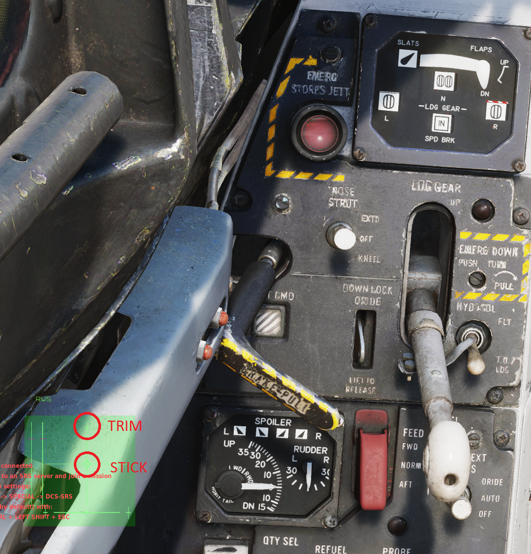
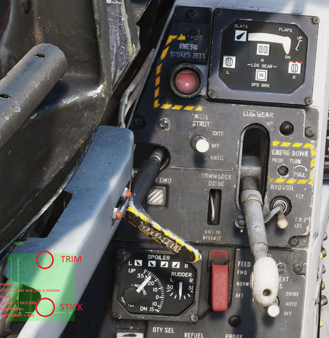
According to the various F-14 flight manuals floating around (see, for example, NAVAIR 01-F14AAA-1, 15 May 1995, Change 1 - 1 February 1997, p. 7-18), the F-14A/B with AFCS should have a horizontal tail authority of 36° TEU to 9° TED (33° to 12° without ITS) with flaps down and trim set to 000. In 2.7.9.18080, the maximum TEU is approximately 28° without ITS, while the correct value of approximately 36° TEU can be attained with the stick fully trimmed back. Stick neutral: Stick back: The maximum TED is approximately 12° (rater a bit more) with and without ITS. The 5° no-trim TEU discrepancy might be the reason why, according to my tests, flaps down rotation at the precomputed rotation speeds from NAVAIR 01-F14AAP-1B, 1 August 2001, p. 249-251 is not attained at 25° TEU as indicated in NAVAIR 01-F14AAA-1, 15 May 1995, Change 1 - 1 February 1997, p. 7-23, but at approximately 20° TEU.
-
In 2.7.8.16140 (not sure when the problem surfaced, but I can recall a time when it didn't exist), the BINGO setting cannot be changed prior to applying ground power when cold starting the jet. When turning the knob, the indicated value does not change. As soon as power is then applied, the value jumps to the value that would have been attained by turning the knob. NAVAIR 01-F14AAP-1B, page 214, states "Fuel BINGO - Set" as one of the Interior Inspection checklist items that are to be completed prior to applying ground power. If in the real jet, the selected BINGO value hadn't changed when turning the knob, there would have been no point in setting the fuel BINGO prior to external power being connected.
-
A similar issue was discussed here.
-
This may be related to the bug described here.
-
Awesome, thanks. Just for my peace of mind: The white markings at the outer edges of the turn scale then do not indicate any specific turn rate, but exist merely to aid the pilot in setting the turn needle between the center and outer markings to establish a half-standard rate turn?
-
I cannot categorically prove that the following is a bug, I would simply ask the dev team to check whether the turn indicator is working as intended. According to NATOPS, "[a] needle-width deflection of [the Turn-and-Slip indicator's] pointer will initiate a 360° turn in 4 minutes." Tests conducted by me have confirmed that this is correctly simulated. A needle-width deflection thus indicates a half-standard rate turn. However, a two needle-width deflection (put the white on the white) which I would expect indicates a standard rate turn in fact does not do so in the game. My tests have shown that a 180° turn with said deflection takes approximately 50 seconds instead of 60. Some basic aerodynamic math confirms the discrepancy: For example, at 289 KTAS, a 3° per second turn rate should be achieved at a bank angle of 38°. In the game, at 289 KTAS, a two needle-width deflection coincides with a bank angle of approximately 44° on the VDI. If the indicator is modelled correctly as is, I request information about how (or if) RL F-14 pilots were able to fly standard rate turns precisely. Incidentally, I can confirm the findings reported in this post concerning a significant difference between the bank angle indicated on the VDI and the Standby Attitude Indicator.