F16FLCS-SME
-
Posts
228 -
Joined
-
Last visited
1 Follower
-
fixed FLCS Bit Animation not a Digital FLCS Bit Blk 50
F16FLCS-SME replied to CypherBlue's topic in Bugs and Problems
The flight control system (analog and digital) has no control what so ever over the speed brakes. That means FLCS BIT can't open/close them. They are controlled manually by the throttle switch. Analog FLCS will drive the control surfaces fast. Digital FLCS was fixed to prevent hard demand from the hydraulic systems so they will move slower during BIT. -
missing references FLCS PWR switch at MAINT logic
F16FLCS-SME replied to F16FLCS-SME's topic in Bugs and Problems
Well, I always tested the system with the external power cable connected. I maintained block 40. Probably my fault. Disregard. Not having access to T.O.s is a big problem, since I don't remember everything without proof... -
This is called a diamond profile because it resembles the shape of the lower part of a diamond. The LEFs will move to -2 degrees in the transonic region.
-
missing references FLCS PWR switch at MAINT logic
F16FLCS-SME replied to F16FLCS-SME's topic in Bugs and Problems
Is this a simpit or RL? If RL, is the external electrical power cable connected? Which block is it? -
missing references FLCS PWR switch at MAINT logic
F16FLCS-SME replied to F16FLCS-SME's topic in Bugs and Problems
This thread is marked "missing references". Unfortunately, I have retired so I don't have access to T.O.s. However, if you have access to J.G. 24-00-07 (Flight Control System Power Operational Checkout) or to the schematic diagram 24-00-07 at 24FI, you will see the correct logic. -
Latest beta. First training mission. 1. Move MAIN PWR switch to BATT. 2. Move FLCS PWR switch to MAINT. FLCS RLY remains ON. That's a bug since in MAINT mode, all power is cut to the FLCS so the Converter/Regulator cannot drive the FLCS RLY light. It should be OFF. By the way, the switch should not make a sound in TEST since it is spring loaded, not lever locked. The sound should be only between MAINT and center position. 1. Move MAIN PWR switch to MAIN PWR. 2. Move FLCS PWR switch to TEST. TO FLCS light will come ON. 2. Move FLCS PWR switch to MAINT. Same bug, that light has no power and should be OFF.
-
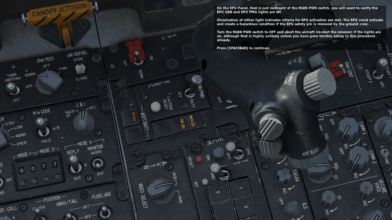
EPU GEN, EPU PMG at aircraft startup training mission
F16FLCS-SME replied to F16FLCS-SME's topic in Missions and Campaigns
Almost 2 years have passed since I reported that bug. Nothing got fixed. The narrator and the mission text claim that the EPU GEN and EPU PMG caution lights are on the EPU panel. However, they are on the ELEC panel. @BIGNEWYYou promised me you reported it to the mission creator...
-
Page 48: "The dilute lever can be set to normal O2 mixture or 100% 02" Its 100% O2, not 100% 02. Page 48: "It is activated by placing the switch in the ON position or it can be set to AUTO and will automatically turn one" turn on, not one.
-
Page 44: "The anti-collision knob has an OFF and seven options that apply to the anti-collision lights when in flashing mode:" That light is a single light, not lights. Page 44: "To the right of this is the Master Covert knob that has positions for external lights overt and convert" covert, not convert. Page 45: "Below the switch is the Electrical Caution Reset button that can clear electrical system caution lights" The ELEC SYS caution light is a single light, not lights.
-
Page 43: "Once complete and successful, the light turns off and the switch snaps back to center." This switch has no center position. It will snap back to OFF. Page 43: "On the leftmost side is the Master Fuel switch, which is guarded. It opens or closes the main fuel shutoff valve. This is normally guarded to the on position." There is no ON position. It is MASTER position.
-
Page 41: "When a PFLD item is displayed, its corresponding caution light indicator will illuminate and the and the master caution light will be lit." and the appears twice. Page 43: "The Digital Back Up, or DBU switch, selects the FLCS backup software. If enabled, you will see the DBU caution light and a HUD warning." DBU ON is a warning light, not a caution light.
-
Page 35: IFF Identification Light. Fault Acknowledge Light. Those are not lights, just buttons. Page 35: "The left multifunction display, or MFD, consists of a full color CRT" In 2007, I don't think it was a CRT. I think it was already replaced to LCD.
-
Page 34: The picture has an empty text box under the DED label for the right eyebrow warning lights. Page 34: "The angle of attack indexer consists of three lights. If the top light is illuminated with a red chevron, you are above 14° of angle attack and you are pulling with an energy depleting angle of attack." English is not my native language but the part "you are above 14° of angle attack" does not seem grammatically correct to me.
-
Isn't JFS doors animation still a WIP?
-
The gearbox mechanically links the motor, pot, needle and thumbwheel. If the motor moves, everything else moves, so the pot sends a new value to the FLCS. If the thumbwheel is manually moved, everything else moves, so the pot sends a new value to the FLCS. The motor is quite strong, but can be stopped by holding the thumbwheel in place. The gearbox has a clutch so the motor will keep spinning without damage. Whenever I replaced a trim unit, I had to calibrate it so when the thumwheel is centered, the needle is centered and the pot signals 0 ohms. The motor is an AC motor so has no center position. Regarding the priority, I don't have access to the schematic drawings (27FI/GS) and I don't remember... The pilot (forward seat) has priority over the aft seat.