Stickler
-
Posts
52 -
Joined
-
Last visited
Content Type
Profiles
Forums
Events
Everything posted by Stickler
-
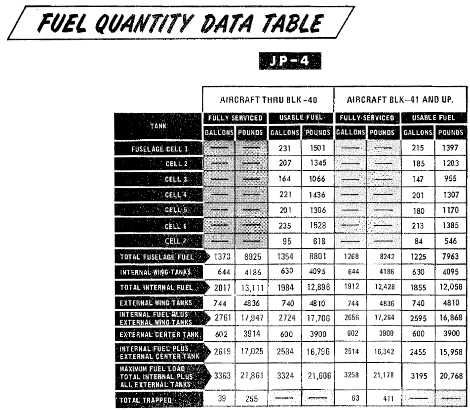
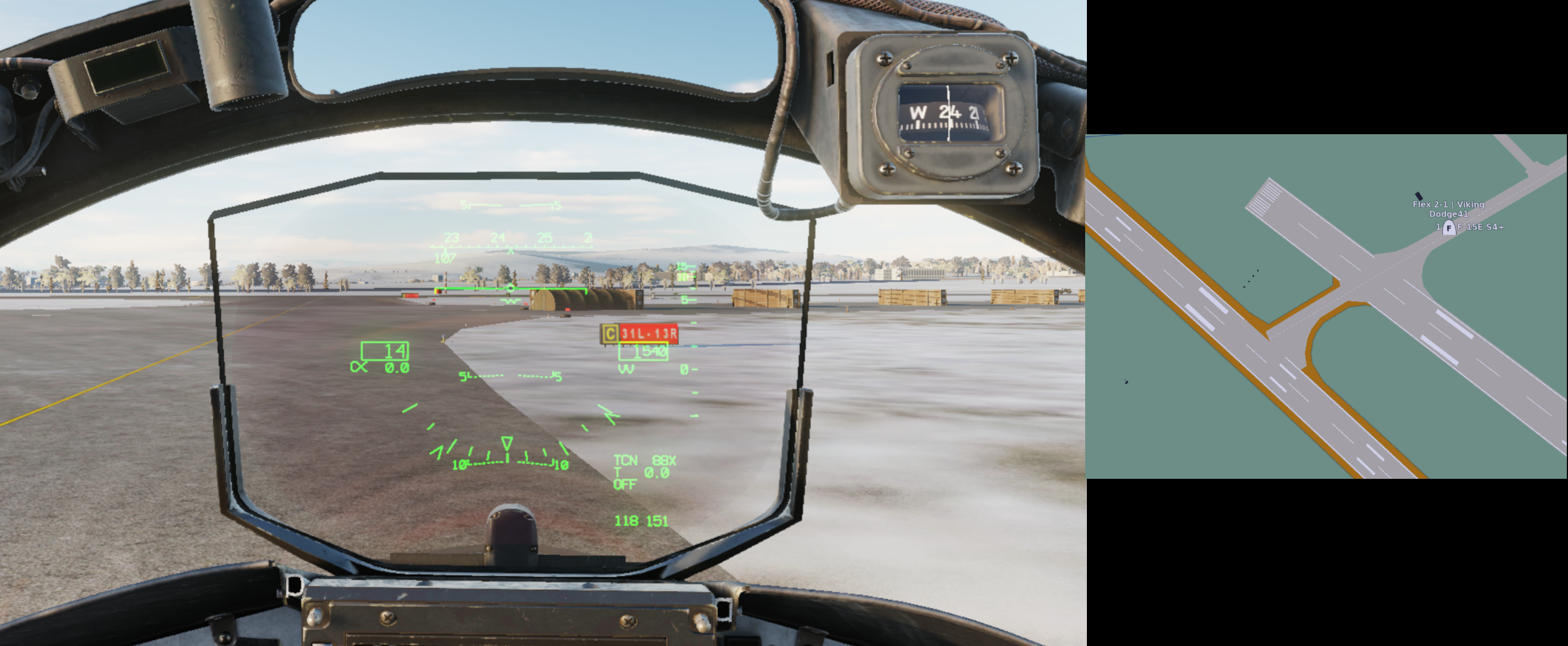
The introductory video at the 0:34 mark says that Heatblur's "vanilla" F-4E is the 45-MC. According to the game manual, the aircraft simulated has a maximum internal fuel of 12896 lbs: Tanks - Heatblur F-4E Phantom II According to TO 1F-4E-1, 1 Feb 1979, p. 1-12 (attached), the maximum usable internal fuel of Block 41+ aircraft is 12058 lbs; the 12896 lbs is correct for Blocks up to 40. Also, the manual mentions 315-gal wing tanks here: Engines & Fuel Systems - Heatblur F-4E Phantom II. I have no record of 315-gal wing tanks being used on the F-4E and I suppose 370-gal is meant here as on the other page of the manual linked above.

-

[EU TZ] 526th vTFS (CJTF-13) looking for procedure-oriented F-4E crews
Stickler replied to Stickler's topic in Jets Squadrons
526th vTFS is now open for applications. -
I've been preparing documentation/doctrine for an F-4E squadron within EU Milsim Battalion – The Art of Warfare (tawdcs.org) since November. Check out the recruitment thread: Key facts: Milsim European Time Zone Squadron based on 526th TFS, Ramstein AB, Germany Based on/using available real-world documentation/procedures as far as possible/practicable
-
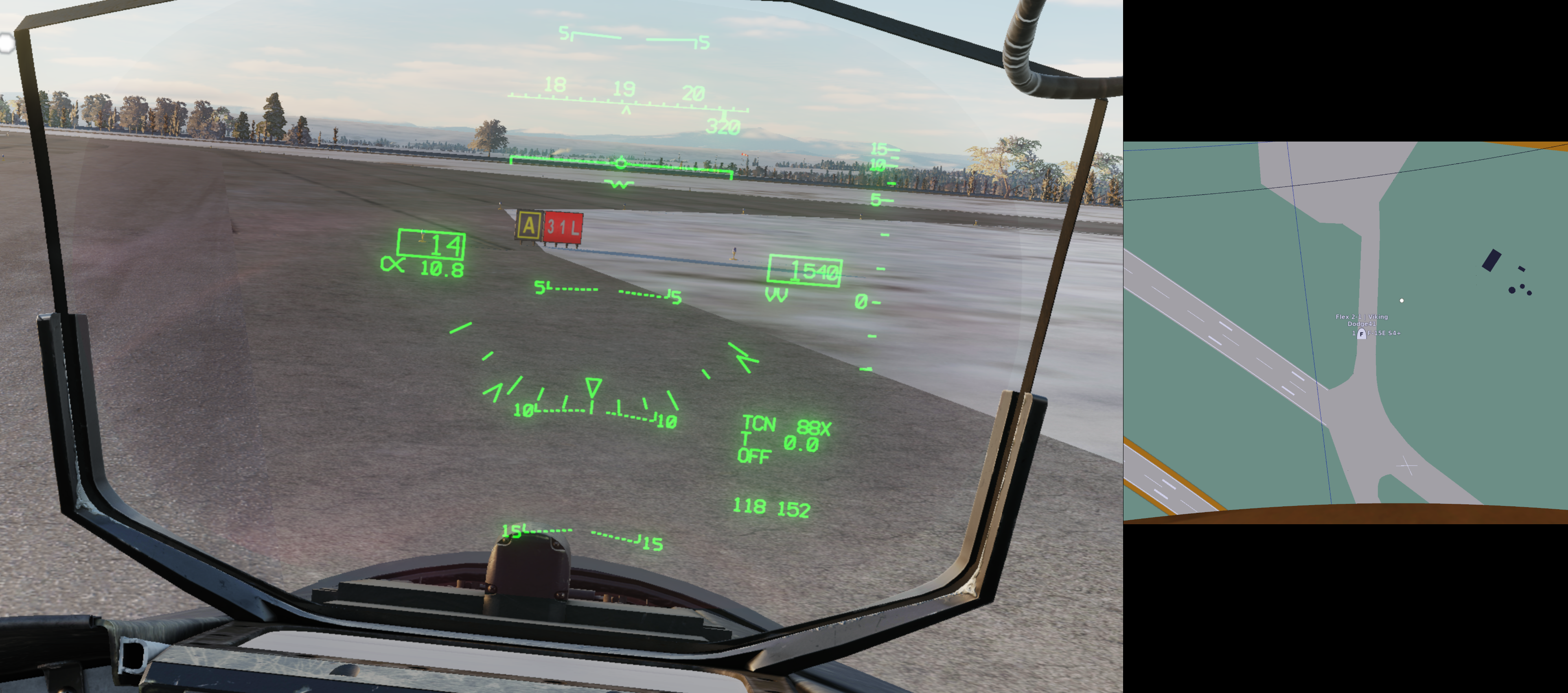
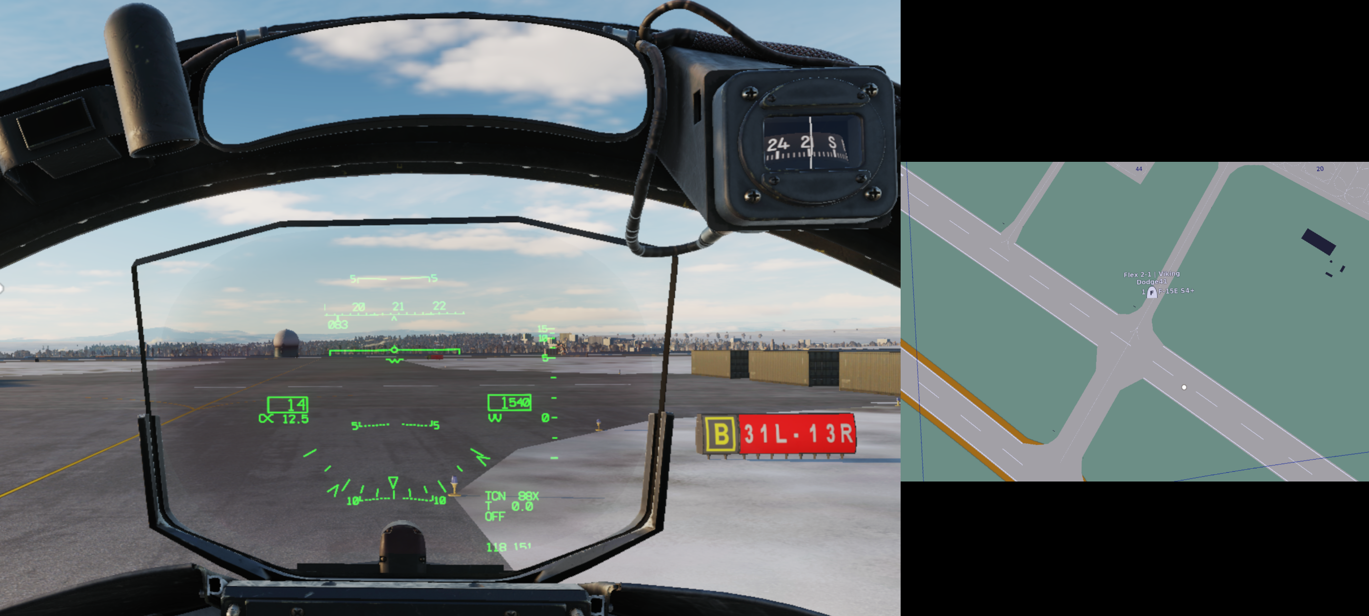
Observe the following screenshots: Note how in the first situation, RWY 31L is indicated whereas the player is located in front of RWY 31R, in the second and third situations, RWY 31L-13R is indicated whereas the player is located in front of RWY 31R-13L.
-
The screenshot below shows me on a perfect 3° glide path to Tbilisi RWY 13R using the Mirage F1's autopilot. Note how the PAPI left of the runway indicates 4 red. To get 2 red, 2 white at Tbilisi RWY 13R in DCS, one needs to fly a glide path of approximately 5°. According to the RL Georgia AIP, both the PAPI and the ILS glide slope are calibrated to an angle of 3.5°. Haven't checked RWY 31L.
-
[DCS ISSUE] Mk 20 Rockeye canister not (always) opening
Stickler posted a topic in Bugs and Problems
I'm aware that the Mk 20 Rockeye is currently incorrectly simulated as clearly demonstrated by any 34-1-1 of your preference featuring the Mk 20 and by Karon's extensive testing (The Mk-20 Rockeye Cluster Bomb: Observations – FlyAndWire). However, until today I assumed that the incorrect simulation was at least consistent, but alas this assumption seems to be unwarranted. As shown in the attached .acmi featuring two Mk 20 lofts with very similar release parameters and trajectory, the first canister opens while the second does not. No switch settings were changed between the releases. Can anyone explain the logic? Is this problem specific to the F-14 or does it affect DCS in general? rockeye.acmi- 1 reply
-
- 1
-

-
Tacview, the ACMI for DCS World – Official Thread
Stickler replied to Vyrtuoz's topic in DCS Modding
Noticed the following discrepancy in 1.9.1 (not sure if it existed before) which is best explained watching the attached .acmi: When the aircraft is in a pull-up, the pitch as indicated by the HUD view aircraft symbol and the "Pitch" value in the Telemetry window seem to match exactly, which is as expected. Conversely, the γ value seems to lag the flight path marker quite a bit. For example, when the flight path marker in the attached .acmi reaches 20° nose up, the γ value is approximately 17,8°. Shouldn't these values be the same? Which is the "correct" indicator for the physical flight path of the aircraft, the γ or the position of the flight path marker? pull-up.acmi -
The following observations are from 2.8.4.39313 (MT), not tested in other versions. All values are approximate. RALT bug (ft) - Warning tone/light (ft) 450 - 450 800 - 900 1000 - 1800 2000 - 3000 3000 - 3900 The warning tone/light therefore come on significantly before they should based on the RALT bug setting. Occurs in SP and MP.
-
Sorry to necro the thread, but in which way are GBUs affected by the EFUZE setting in the game (not asking about RL) other than the fact that setting the EFUZE to SAFE will cause them to dud?
-
Tacview, the ACMI for DCS World – Official Thread
Stickler replied to Vyrtuoz's topic in DCS Modding
.acmis attached as requested. HEI.zip.acmiAP&HE.zip.acmi -
Tacview, the ACMI for DCS World – Official Thread
Stickler replied to Vyrtuoz's topic in DCS Modding
Reporting another issue related to the F-14, but this time it looks as if the problem is really on the Tacview side: When selecting the different F-14 M61A1 ammunition types in the mission editor, the following ammunition is shot as per Tacview: 20 mm HEI: M56A3_HE_RED 20 mm API: M53_AP_RED 20 mm AP&HE: M56A3_HE_RED 20 mm TP: M55A2_TP_RED According to my post in the F-14 bug forum, everything SHOULD be correct on the F-14 module's side. I'd appreciate if you guys could check your code, maybe there's a simple typo that causes the issue. -
Copy, I'll post a bug report in the Tacview thread.
-
When selecting the different M61A1 ammunition types in the mission editor, the following ammunition is shot as per Tacview: 20 mm HEI: M56A3_HE_RED 20 mm API: M53_AP_RED 20 mm AP&HE: M56A3_HE_RED 20 mm TP: M55A2_TP_RED Therefore, there doesn't seem to be a difference between the 20 mm HEI and 20 mm AP&HE selections. Furthermore, based on reviewing .trk files with the different ammunition types shot against a specific target, the visual effects of bullet impacts seem to be identical. Especially for TP ammunition I would not have expected too see small impact explosions as with the other bullets. Are differences in bullet effects/ricochet/range actually modelled? Are the apparently identical HEI / AP&HE ammunition types an error in the module or in Tacview?
-
Tacview, the ACMI for DCS World – Official Thread
Stickler replied to Vyrtuoz's topic in DCS Modding
OK, so I'm 99% sure now that Tacview works correctly. The issue was the weird and prehistoric way the F-14 and Mirage F1 HUDs function (see the post I linked above). Sorry for the additional work. -
Target position in HUD does not match target position in Tacview
Stickler replied to Stickler's topic in Bugs and Problems
OK, I think I've figured it out thanks to the first part of your comment. I was departing from the assumption that you could derive target placement and pitch from the HUD ladder simultaneously. Due to how the HUD works, this is incorrect. You can only ever get one or the other with a specific HUD trim. This means that, for example, if you calculate a 30° dive attack with a 33° initial target placement (ITP), provided you fly the geometry perfectly with a default 5° down HUD trim, your apparent ITP at the track point will instead be 28°. Confusingly, you'll now need to set 30° instead of 25° pitch on the HUD to reach bomb range at the planned release altitude. I have not read anything about the rungs not being linear nor can I confirm this by testing. Using the ELEV LEAD knob and MAN mode as a reference, there are 86 to 88 mils between the rungs, mostly 86-87. While this means that the HUD calibration is slightly off (89 mils would be most accurate), IMHO this is close enough for government work. So summing up, the problem is solved on my end. Still a weird HUD for A/G employment, but then again it wasn't designed for that purpose. -
(MT) A/G HUD pitch ladder not graduated as per NATOPS
Stickler replied to Stickler's topic in Bugs and Problems
While I cannot rule out that the real HUD was in fact not graduated as per NATOPS, I would like to offer the observation that when superimposing the CCIP and the aircraft symbol using the ELEV LEAD knob in MAN mode, approximately -86 mils are obtained. With the maximum ELEV LEAD setting of -263, the difference is 177 mils. Converting this to degrees: 9.95625°, which very closely matches the NATOPS value of (-)10°. Why would it be possible to set the manual sight to approximately -10° if the pipper (center dot) already disappears from view at a setting of 223 mils (= 7.7° from the aircraft symbol)? Bad engineering by Grumman? -
Target position in HUD does not match target position in Tacview
Stickler replied to Stickler's topic in Bugs and Problems
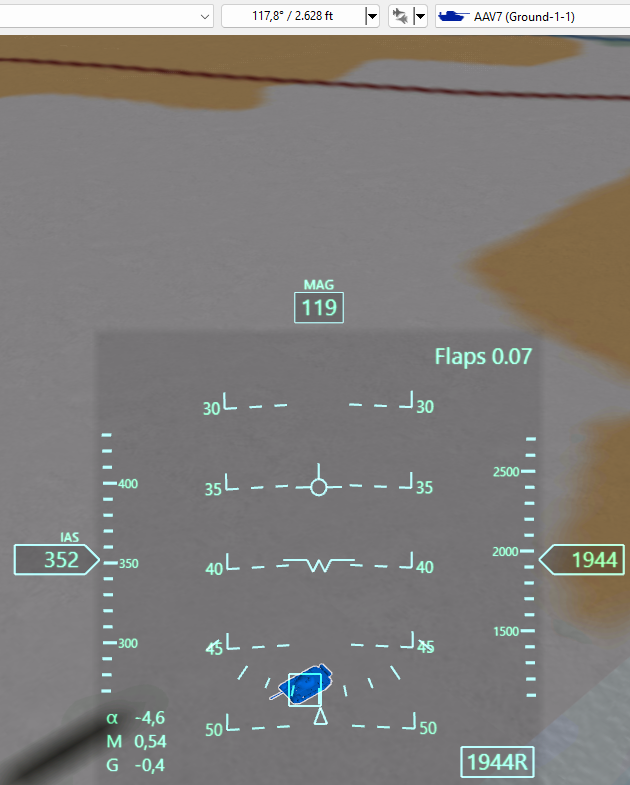
It's getting a little bit clearer now, but I have not been able to fully grasp the problem. Consider the following screenshots showing the same situation in-game and Tacview: Both DCS and Tacview correctly show the aircraft's pitch to be -40° (this matches the "raw" pitch shown in the F2 view, screenshot not included). Looking at the math of the situation: F-14 altitude = 1944 ft MSL TGT altitude = 11 ft MSL (not shown) ATL = 1933 ft Slant range F-14 to TGT = 2628 ft Ground range therefore (Pythagoras) = 1780 ft The target position angle (TPA) with reference to the physical horizon is then calculated as: TPA = arctan(1933/1780) = (-) 47.35° This is pretty much exactly the TGT position as shown in Tacview. The F-14's HUD has the target beneath the (approximately) 43° line. Since the HUD shows the pitch correctly as per the F2 view, I'm going to assume the target really is at 43° with reference to the pilot's eye position. If we calculate backwards to find the pilot's eye position altitude (ATL), we can say: ATL = tan(43°) x Ground range = 0.93 x 1780 ft = 1660 ft The pilot's eye position is therefore 273 ft (1933 ft - 1660 ft) below the aircraft considered as a point in space. With the aircraft having a vertical extension of 16 ft total, how is that possible? What am I doing/thinking/calculating wrong?
-
Target position in HUD does not match target position in Tacview
Stickler replied to Stickler's topic in Bugs and Problems
Thanks for the reply, but I don’t understand what you‘re saying and how exactly this explains what I’m seeing. Could you elaborate? -
Tacview, the ACMI for DCS World – Official Thread
Stickler replied to Vyrtuoz's topic in DCS Modding
Additional info on the target placement issue: Contrary to what I expressed above, the problem does seem to be limited to certain aircraft in that it does not occur with the F-16. See below. I still don’t understand what‘s going on. -
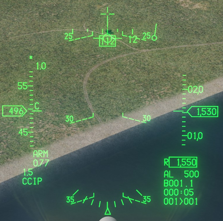
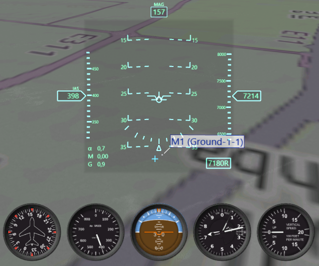
I initially thought this was an aircraft-agnostic Tacview problem (see post below) but now I'm not so sure anymore. Compare the following screenshots and .acmis taken from an attack by an F-14 and an F-16 against the same target. F-14.acmi F-16.acmi In both the F-14 and F-16, the target is on the -25° degree line on the in-game HUD and the pitch of the aircraft is approximately -25° as indicated on the HUD, the F2 view and in Tacview. However, in the F-14.acmi, the target is located on the -30° degree line, while in the F-16.acmi it is located on the -25° line. The same mismatch between the in-game HUD and the Tacview HUD view also occurs in the Mirage F1. I have not tested other aircraft. I am at a total loss how this is even possible. If it was a wrong HUD trim, surely the F-14's pitch as indicated by the aircraft symbol would not be consistent between HUD, F2 view and Tacview. Any ideas?
-
Tacview, the ACMI for DCS World – Official Thread
Stickler replied to Vyrtuoz's topic in DCS Modding
Sure. Attaching .acmi and corresponding screenshot of my Caucasus test. Tacview-20230404-200825-DCS-maptest.zip.acmi Time is +01:50 into the recording (active pause). Note the target under the -15° line on the screenshot and under the -20° line in the Tacview HUD view.
-
Tacview, the ACMI for DCS World – Official Thread
Stickler replied to Vyrtuoz's topic in DCS Modding
There seems to be a bug with unit positioning in .acmis in 1.9.0 and DCS Open Beta 2.8.3.38090 MT (not tested in other builds or versions). See the attached screenshots which were taken at the exact same moment in time for the F-14 and the Mirage F1, respectively, using active pause. Comparing the HUD screenshot from in-game and Tacview, it becomes apparent that while for both aircraft the pitch angle is captured accurately, the target is displaced by approximately 5° below its position in the Tacview HUD view compared to the aircraft's HUD. The target is located in PG, N24°35.957 E054°42.910. Since the same problem occurs in two aircraft types I suppose the modules by themselves are not causing the issue. Also tested this in Caucasus against a different target (APC, not tank as in PG) and I get the same result (5° displacement).
-
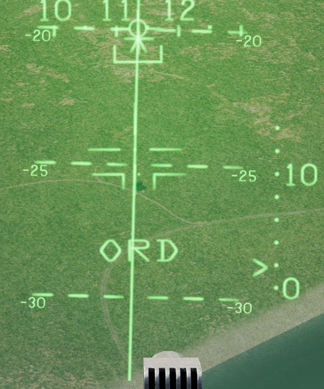
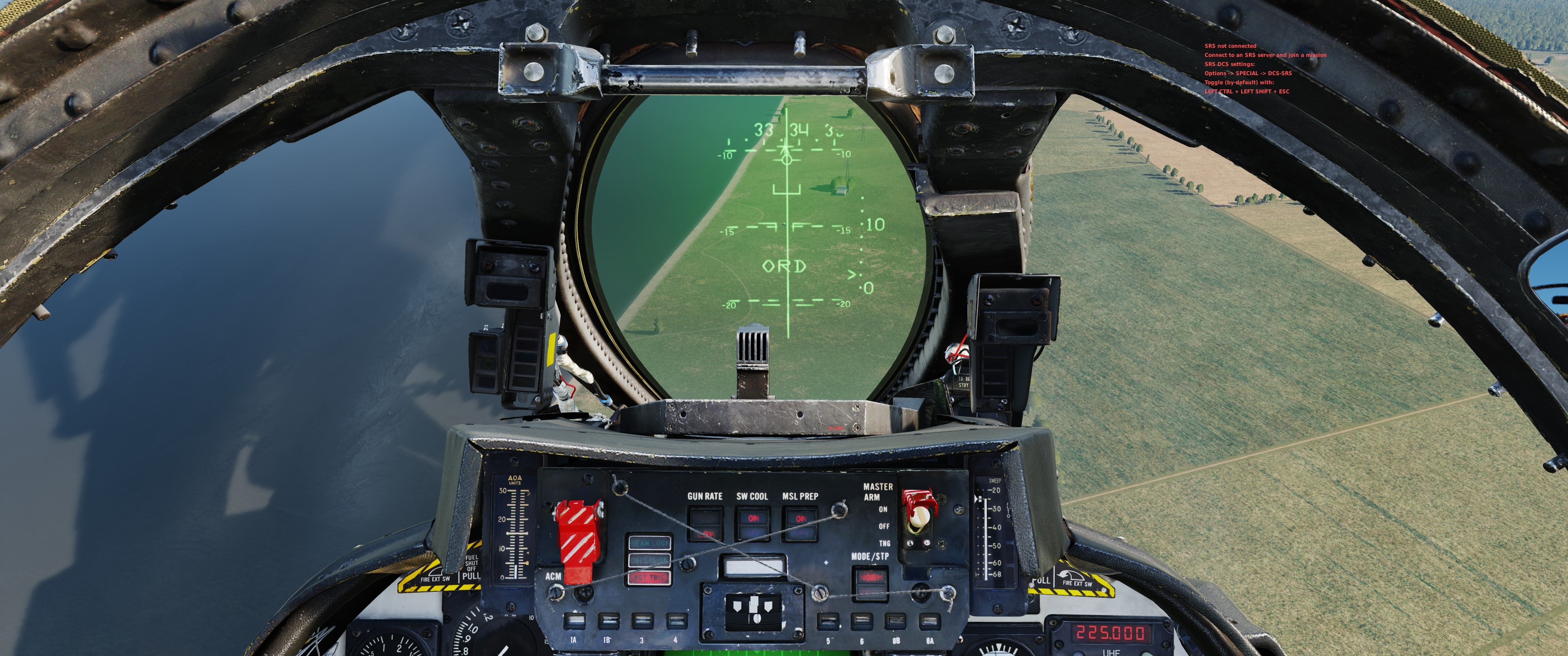
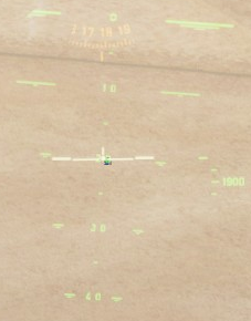
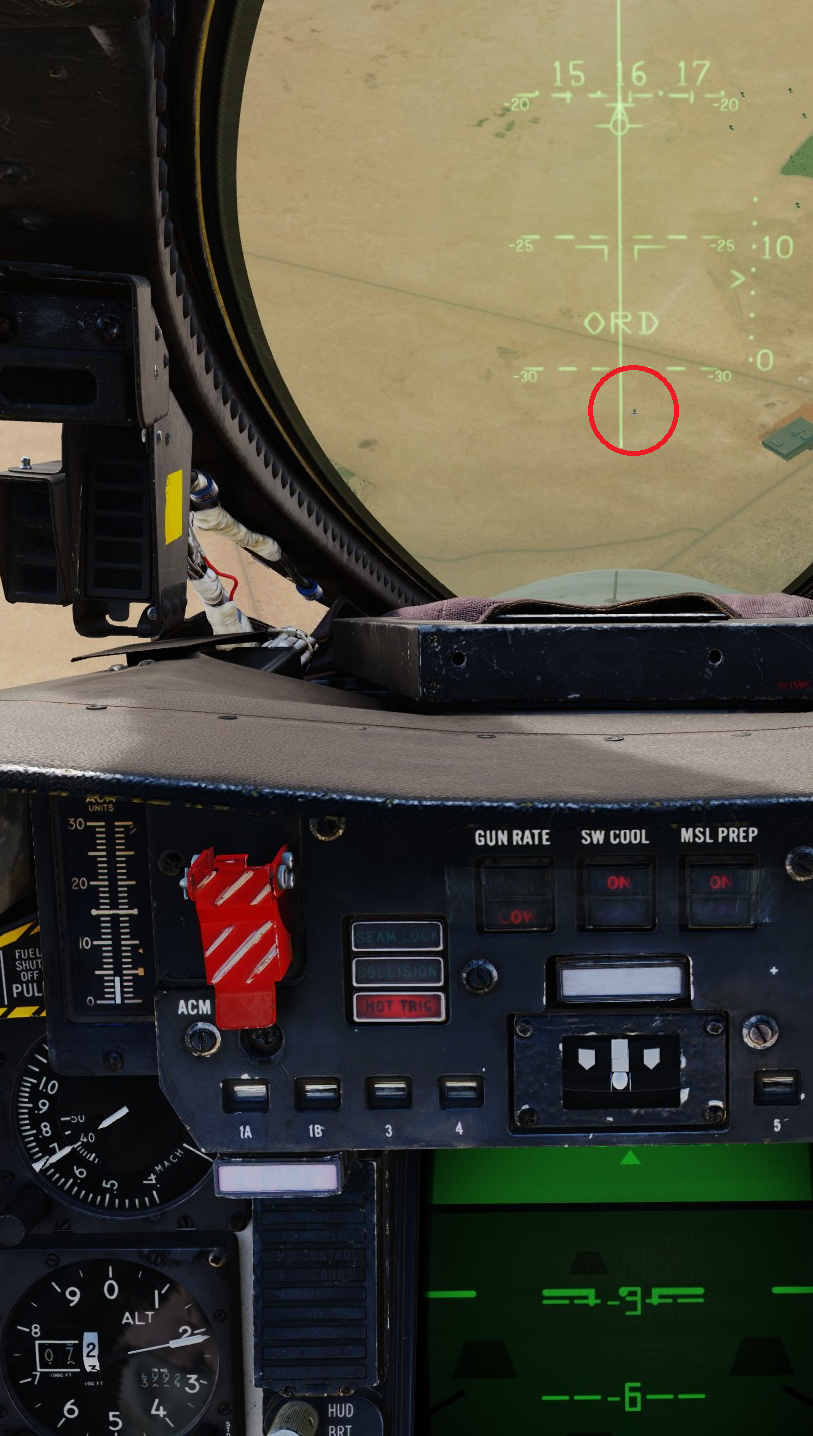
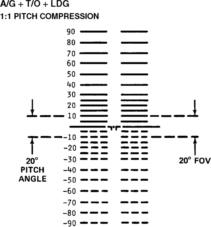
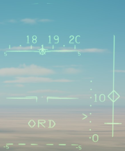
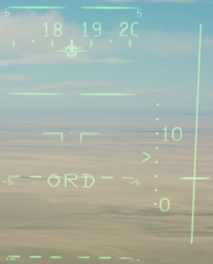
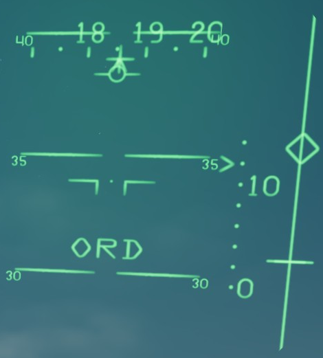
According to the -A and -B NATOPS, the A/G HUD has a vertical FOV of 20° centered on the aircraft symbol (10° up, 10° down). The pitch ladder is graduated every 5° up to 30° pitch up and pitch down, then every 10° thereafter. null In the game, the A/G HUD has an asymmetric FOV of 10° pitch up (note the barely visible 10° mark in the picture immediately below) and approximately 8° pitch down (see the second picture below) with reference to the aircraft symbol, and the pitch ladder is uniformly graduated every 5° (see the third picture down).
-
1. According to NWP 3-22.5-F-14A/B/D, VOL. III, IC10, p. E-4/E-5, the following conditions need to be met in the F-14A/B before any of stations 3, 4, 5, or 6 can receive an air-to-ground release pulse: A. Landing Gear Handle UP B. ACMP: Master Arm: ON C. Stick: Wpn Select: OFF (GUN if mixed) D. PDCP: MODE: A/G E. ACP: WPN TYPE: Store type F. ACP: DLVY OPTNS: QTY: 1 or more G. ACP: STA SEL: 1 or more loaded stations: SEL H. ACP: FUZE: MECH and/or ELEC not SAFE In the game, I have noticed the following deviations from this logic: Bombs can be released with the gear handle down Bombs will release even though both MECH and ELEC fuses are set to SAFE Bombs will release without any store type selected (wheel set to OFF) Bombs cannot be released if WPN select is set to GUN with "Mixed" selected in the back seat Bombs can be released if QTY set to 00 2. According to both NWP 3-22.5-F-14A/B/D and the flight manual, ITERs and ITER-loaded stores cannot be jettisoned. In the game, depending on the WPNS/MER TER selector, both ITERs and ITER-loaded stores can be jettisoned. 3. In the game, fuel tanks can only be jettisoned with WPNS selected, not with MER TER. I have found no indication in the above manuals that an MXU-611 cannot be jettisoned, however I have not found any information that it CAN be, either. Therefore, not sure if this is a bug. 4. The "jettison" sound sometimes occurs even if no stores are actually jettisoned. To reproduce, load stations 3 to 6, select MER/TER, perform a selective jettison of all stores, then repeat. I assume the "clunk" sound is meant to simulate the haptic feedback the pilot receives when a heavy store leaves the jet (as opposed to the jettison cartridges firing which could not be heard from within the cockpit), so when no store actually leaves the jet the "clunk" should not be heard. Even if the sound is intended to simulate the sound of the jettison cartridges they could certainly not be heard twice since they are one-shot.
-
Please help me explain this loss of STT TID tracks
Stickler replied to Stickler's topic in DCS: F-14A & B
Thanks @Noctrach, looks like I'm not crazy after all. I think the loss of lock/track due to roll and the loss of track due to ATA and pitch might be closely interrelated but they need not necessarily be the same issue. I can hold an STT-generated TID track all day long with 90° or even 180° AoB provided my ATA remains close to 0°. So the "antenna elevation + azimuth + roll > 55°" relation is probably not really additive (at least with regard to roll); if it was, you'd certainly lose the track at 90° AoB. I incidentally found that if you set 40° ATA, then roll inverted and then push the stick forward, the track will be lost when reaching around +15° antenna elevation as well. In any case, no need to debug this further on our end since this has been reported twice now. @WarthogOsl I'd say it's dropping STT-generated TID tracks when it shouldn't. Since I do not have access to the original aircraft's AWG-9 manual I cannot prove my point but I can hardly imagine the real radar couldn't maintain an STT-generated track at 40° ATA, 15° pitch and 0° roll when the radar's limits are ±65° in azimuth and -76°/+54° in elevation, especially since the lock itself can be maintained at these parameters. In other words, why should it be able to maintain the lock but not the track?