Tanarg
-
Posts
26 -
Joined
-
Last visited
2 Followers

-
 I certainly didn't alter DcsBios.h from the standard download, but a quick compare shows that the one you are using does not match mine. Which version of DCS-BIOS are you using and what release? I am assuming a Skunkworks release before 0.3.9 as this introduced Addresses.h and this is missing from your version. See below: ## v0.3.9 - Included Addresses.h as an alternative way of including DCS address/mask information. [Documentation needed]. Thanks @maciekish for the contribution!! - Example of PotentiometerEWMA added to OneOfEverything - Add support for #define DCSBIOS_DISABLE_SERVO to disable inclusion of servo.h on platforms which don't support it (ESP32) - Resolved confusing inclusion pattern for USE_MATRIX_SWITCHES, and supported more standardized version DCSBIOS_USE_MATRIX_SWITCHES. Have you got things working with the attached code, if not I suggest that you address this first, before introducing DCS. Qualia_TFT_Example_480x480.ino
 -
A few things: Finally got around to mounting the gauges in my F-18 Cockpit, four of the smaller displays and two of the larger ones. I also noted that I missed a line of code out of the Qualia sketch. You won't notice it unless you don't call the BIT. If you don't, there is nothing to initially draw the screen until DCS outputs something. Simple solution add "plotRadarAltGauge (angleRadarAlt, angleMinHeightPointer);" above the BIT call and it will work as intended. An odd one, but you might note on the RALT display in the picture that the altitude needle is not showing zero on the ground, whereas the one in the DCS cockpit is. Once you gain some height they are in sync. It seems to be something DCS is outputting on start-up. I am not currently sure how to fit this. The needle moves over its entire range in the BIT and once flying. You will also note that the RALT now has an rotary encoder, with push switch installed that works fine, but the code is running on one of the ESP32's driving the smaller displays as I still can't seem to find out why DCS-BIOS does not seem to like the pins on the Qualia board (anyone have an answer please share).

-
F-18C RALT Building on the previous Qualia based display. This one is the Radar Alt for the F-18C. Somewhat more complex in terms of the number of parts and that they are layered. Effectively the display is broken into two parts, the needles and the lamps. The needle handling is very similar to the previous example, using push.Rotated to push the needle position onto the background at the appropriate angle. The minimum height pointer graphic is the reverse of what we have used before. The graphic is mainly transparent with only the reverse triangle at the top in white and the pivot point in the transparent area at the bottom. The lamps don't need to be rotated, so we use pushToSprite instead. Remember we can't use pushImage as drawing to the screen is taken care of by GFX. The red and green lamp functions are almost the same with 0 for off and 1 for on, so if the value returned by DCS-BIOS is 1 we create the associated sprite and push it to the background sprite, overwise we don't and skip over the code. The OFF flag is the same except it's two values are 0 and 65535, nothing in-between. The 65535 value corresponds to 5,000ft over which height the RADALT is not accurate, and hence turned off. As usual there is a BIT test to use if required. Written for FP (Skunkworks) I have not provided the code to replicate the push to test and altitude set function (simple to add) as this requires additional hardware and needs some further work on the integration to the Qualia ESP32S3 board. I will update once this work is done. As usual any comments/questions welcome. F_18_RALT_Gauge_Qualia_FP.ino radarAltNeedle.h radarAltOffFlag.h radarAltBackground.h radarAltGreenLamp.h radarAltLowAltWarning.h radarAltMinHeightPointer.h
-
F-18C Cabin Pressure Gauge Something a bit different this time. I have been looking for a bigger round display to cope with some of the larger cockpit gauges. The next size I have been looking for was 2-2.5 inch and I found the best fit was a 2.1 inch round ST7701S display I found on AliExpress. The display at this size uses 480x480 pixels, so this presents some challenges in terms of driving it. At this resolution you can't really use a SPI (serial) connection, it's just not fast enough. The ST7701S uses a mixture of SPI for config and parallel to move the data. The second point is that the bitmaps at this scale are four times the size of those on the smaller displays I have been using. A third point is that the ST7701S interface is not widely supported. As an example it is not supported by TFT_eSPI, which you will note from above I widely use. To get around these issues I found the Adafruit Qualia ESP32S3 board. It provides a parallel link to the ST7001S display and the on-board ESP32S3 has enough memory (for this sketch I used 41% of it's available memory). It used the GFX library for communications and graphics handling. As far as I can see the GFX library does not provide all the functionality that I wanted particularly in respect of sprite handling. Fortunately, we can use both TFT_eSPI and GFX libraries at the same time. TFT_eSPI to do the graphics manipulation and GFX to push the resultant image to the display. This seems to work well, and performance seems good. Be careful though if you want to add additional code. For example, you will note that I do not initialise TFT, it doesn't appear to be needed in this situation and it you try will likely find the sketch will compile, but not work (at all). You will find that the sketch follows my normal format, but with a larger configuration section at the top. Note that you do not need to configure TFT UserSetup.h as this part of the config is done by GFX in the sketch. As usual, I have added a BIT test, which I find useful for testing, you can comment out if not required, otherwise it will run once on start-up. The sketch is written for DCS-BIOS FP, if you are using the original version, you will need to change 0x7514 to 0x7504 in the DCS-BIOS section of the code. FYI, the Qualia board does support other ST7701 display sizes if required. Now that I have this size of display working, I am thinking that the F-18 RAD ALT should be my next project. Comments/Questions welcome. cabinPressBackground.h cabinPressNeedle.h F_18_Cabin_Pressure_Gauge_Qualia_FP.ino
-
For those using DCS-BIOS FlightPanels, amended files attached F_18_ThreeGauge_FP.ino F_18_Battery_Gauge_FP.ino F_18_BrakePressure_Gauge_FP.ino F_18_HydralicPressure_Gauge_FP.ino
-
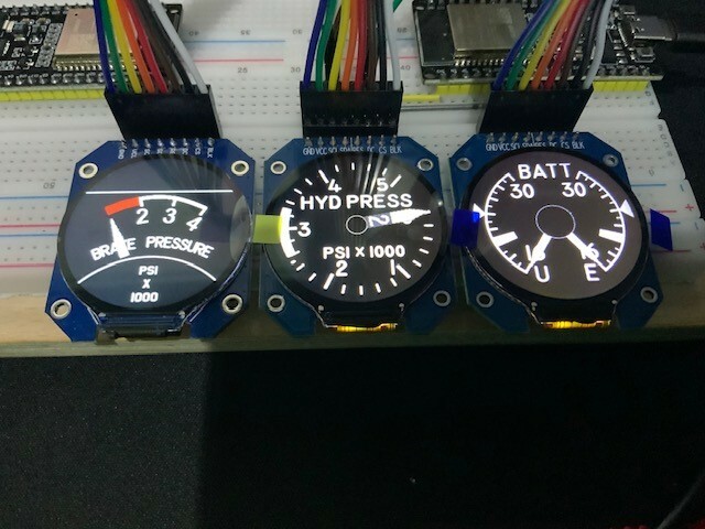
Example 4 – Three Gauges driven from single ESP32 (F-18_ThreeGauge.ino) The individual gauge mechanics and coding of this example haven’t changed from the previous examples, except in same cases to avoid name conflicts or have more consistent naming. I will concentrate on the additional coding required to get all three displays working on the single ESP32. Hardware This is the first fundamental area of change. Normally you would have TFT_eSPI control the pin outs in User_Setup.h. This would include which pin you had been using for Chip Select (CS). This pin is used to identify the display the program is going use – normally this is a single display and does not change. In this case, we want to comment out the ‘CS’ line in User_Setup.h. In its place we are going to control the pins used at any given time via the sketch. We want to end up with each display connecting to the same pins except for the CS pin, where they will each connect to a different pin. See drawing1 attached. Multi Display Code As DCS-BIOS is interrupt driven, we can use the outputs from it to know when we need to write something to a particular screen. To write something to a display we need to set the relevant CS pin to low (0) and set it back to high (1) when we have finished. Where appropriate we can write to multiple displays simultaneously. In the first addition we are going to define three displays associating a pin with each, 4, 16 & 17 in my case (lines 20 – 22). To make things more readable we have created four functions (289-311) that can be used to turn on or off one display (Screen) or all displays (Screens). The next change is setting ‘pinMode’ for each display to OUTPUT (89 – 91) As part of setup, we initialise and fillScreen all displays to TFT_BLACK (93 – 96) – ScreensOn & ScreensOff In lines (98 – 113) we set the setSwapBytes status for the Sprites for each display – ScreenOn x & ScreenOff x We then drop down to the plotGauge sections that drive the display for each gauge: plotBatGauge (180 – 193) plotHydPressGauge (220 – 233) plotBrakePressGauge (260 – 270) Each starts with a ScreenOn and finishes with a ScreenOff for a particular Display So, the logic is that something changes in DCS and is picked up by the relevant DCS-BIOS function that we are monitoring. It works out the new needle position for the relevant needle and gauge and calls the associated plotGauge function. At this point we select the relevant display (screen) and turn it on so that we can write to it. We create the appropriate Sprites etc and push them to the display. We then turn the screen off (for writing) and await the next event from DCS-BIOS. Compared to a game like Ping running on all three displays simultaneously, the number of updates from DCS is comparatively small and therefore this interrupt mode of screen handling seems to work fine in testing. The alternative would be creating a separate display handler and some form of time-based display multiplexing. I think this is overkill for what we need. brakePressNeedle.h F-18_ThreeGauge.ino hydPressBackground.h hydPressNeedle1.h hydPressNeedle2.h batBackground.h batNeedle.h brakePressBackground.h
-
Yes, I should have pointed out that these were done with DCS-BIOS HUB as I haven’t changed to Flightpanels yet
-
Tanarg changed their profile photo
-
Example 3 – Brake Pressure Gauge (F-18_BrakePressure_Gauge.ino) Nothing in this one that we have not already covered (Three gauge example to be posted tomorrow) F-18_BrakePressure_Gauge.ino brakePressNeedle.h brakePressBackground.h
-
Example 2 - Hydraulic Pressure (F-18_HydraulicPressure_Gauge.ino) The second example is for the F-18 Hydraulic Pressure Gauge. It follows basically the same format as the first example, except that there are two different needles (because they are numbered as 1 and 2) that run over one another around the same scale. I will only explain the differences which are really confined to the Bit_test. Lesson 4: The thing that confused me to start with was that to get the needles to behave correctly I needed to start counting at -280 e.g. anticlockwise 280 rather than 80 degrees clockwise, whilst I needed to end at +40. At face value the needles start at +80 and go clockwise to end at +40. F-18_HydralicPressure_Gauge.ino hydPressBackground.h hydPressNeedle1.h hydPressNeedle2.h
-
Producing DCS-BIOS Gauges – Example coding and lessons learned Thought that I would share my work to-date on DCS-BIOS controlled gauges. First with three example individual gauges for the F-18, then a more complex example (first example below and attached), building on these gauges, to have them all controlled from a single ESP32, hence saving on COM ports. I will explain the structure of each bit of code and how it all fits together. Happy to take comments or suggestions for improvements. I have kept the code down to the minimum needed. I am using the GC9A01 1.28 inch 3.3v TFT round displays, but I will try to explain where you will have to amend the code if you are using something else. The code should work with any ESP32 that you can program via the Arduino IDE. Hardware First task is to ensure that your hardware is configured correctly. We will be using the TFT_eSPI library, so this needs to be loaded and configured correctly. In particular you need to ensure that the correct driver is loaded (GC9A01 in this case) and that the pin outs are correct. This can be done in the User_Setup.h file within the TFT_eSPI folder. I suggest running the Color Test from the TFT_eSPI examples to check everything is working correctly. It you are using a different display you will have to select an alternative driver etc. Examples The three gauges that I am going to cover are: Battery Gauge Hydraulic Pressure Brake Pressure All three sketches share a common format, with the main differences around the number, position and rotation of the needles. When we get to the three gauge sketch you will notice that, in addition to adding the code to get the displays to work together, I had to change a few of the names to avoid any conflict or just make things more consistent. Lesson 1 – If you are going to make multiple gauges that you might want to later combine into a single sketch, develop a format for all your function and variable names. Producing Graphics The method of producing the graphics is common to all the gauges, so I will start with that. All the gauges consist of a background image and one or more needles. These are converted into ‘Sprites’ in the code which is the most efficient means of using them. I used the following tools for producing the graphics, but alternatives are fine: Paint.net – Used to produce and manipulate .png images. I found that a tool that supported layers was very useful in developing the images, allowed trial and error. I also found myself using Microsoft Paint on occasion when I needed a very basic capability. Icd-image-converter – This was used to convert the .png files into code that the Arduino IDE can use. Background Image – This needs to be produced at 240x240 pixels (for the GC9A01), I kept with 8-bit colors. My experience is to keep the background of the background image black (and I mean black, not dark grey). Lesson 2 – Not doing this proved troublesome later when the needles passed over the not quite black areas and left a trace behind. The final image needs to be converted, in Icd-image-converter, to R5G6B5 format with a block size of 16 bit and Little-Endian Byte order. Once configured in the tool you can use the ‘Show Preview’ option to display the resultant code and cut and paste it into your sketch. Needle Image - This follows the same process as the background. The size of the needle will be driven by your particular gauge, but will be about 80-120 pixels tall and 15 -25 pixels wide. Try to keep the needle symmetrical and an odd number of pixels wide (see pivot later). Keep your needle background color something you are not using elsewhere on the image as once you have imported it into the IDE you will want to use the Find drop down to replace this color code with the one for TRANSPARENT (0x0120). Pivots – You will need to identify pivot points for your background image and needles. The pivot for the background (GC9A01) will be 120x120. The needle(s) pivot will depend on the needle(s), this is where the odd number of pixels for the needle width comes in handy. Lesson 3 - The needle overall size and pivot point must be accurate in the code otherwise you will get all sorts of strange behaviour. Example 1 - Battery Gauge (F-18_Battery_Gauge.ino) Having produced the graphics for your Battery gauge, we can start on the coding. We will need the ‘colorDepth’ regularly, so set a constant for this (7). ‘include’ the two image files, CDS-BIOS and the TFT_eSPI library (9, 10, 14, 16) ‘define’ DCSBIOS_DEFAULT_SERIAL (12) Set up the Sprites, there will be three in this case, the background and two needles (both the same image) (18 – 20) Declare initial values for the needle angles (22, 23) Call the two sections of DCS-BIOS code, one for each needle (U and E) (25 – 37). There are two common lines of code within this that I will explain. The first ‘angleMapU or E’ uses the Map command with the input ‘newValue’ from the DCS-BIOS function, along with the range of possible outputs from DCS-BIOS (0-65535), together with the range of desired values of the needle to produce a needle angle. In the first case the desired needle value we want is on the left of the gauge between -150 to -30, the needle degrees are measured from 0 (12 O’clock position). In the second case the needle is on the right of the gauge and hence 150 to 30 e.g. both needles will start at the bottom and climb upwards. ‘plotGauge’ is then used to plot both needle positions, even if only one has actually changed. Within the setup function (41 – 47) we include the necessary DCS-BIOS call, initialize TFT and fill the screen with BLACK color. There are then three lines of code that impact the Byte order of the graphics. These interact with the Big and Little-Endian settings. You might need to change these in your own projects, but they work in the example here. There is then a call to a Bit_test that will run on power up and cycle the needles through there min – max movement. You can leave as is, or comment this line out as required. The loop function (52) only needs the DCS-BIOS reference. Lines 55 – 69 are the Bit_test. Lines 71 – 82 are the ‘plotGauge’ function. It starts of creating the three Sprites and pushing the needles, as the desired angles, onto the background. The TFT_TRANSPARENT tell the code to not display anything in this color. Once complete we delete the ‘Sprites’ to free up memory. Lines 84-91 create the background, setting the colorDepth, size and pivot point, and pushing the ‘Battery’ image onto the screen. Lines 93 – 99 and 101 – 107 create the two needles, note the difference between the total size of the needle and its pivot point. If you have done everything correctly you should be good to go…. F-18_Battery_Gauge.ino BatteryBackground.h Needle.h
-
The green and yellow go, no-go lights by the push button switch
-
Having had a look at flight panels, I am not sure that this will solve the problem as I don’t see anything new there on this. As the lights don’t work in DCS itself, I think the problem is there.
-
ok, thanks I am using HUB, for everything. Don't want to change to Flight Panels unless I have to
-
Anybody got the F-18 HUD Video BIT working in DCS-BIOS? The switch works on screen, but does not seem to have any impact on the two lights (Go - No-Go) - which suggests that there is no code behind this. In DCS-BIOS, I can map the switch no problem, or a light (that seems to come on when the switch is pressed, not related to Go or No-Go. You also can't have both the switch and LED wired in DCS-BIOS as there is a naming conflict. Any ideas?
-
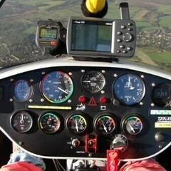
Yes, the backup instrument cluster is a monitor run on Helios (had great fun finding one of the right size to fit in the allocated space and still drive the instruments at scale). The small ones are Tek Creations. Helios also drives the Winwing screens, because mixing the technologies was causing fun.