Gremlin77
-
Posts
297 -
Joined
-
Last visited
Content Type
Profiles
Forums
Events
Everything posted by Gremlin77
-
Wow these instruments are super impressive! I like the 3d relief of your front panels. Mine are all quite flat....
-
Okay, lets talk about pricing. The tornado cockpit was totally empty and so it was not so expensive ( think it was about 3000 to 4000€). It was from a company that restores planes for museums, and the shell was the rest. An expensive thing was transportation with about 1000€ and the ejection seat with about 2000 €. But think about buying all separate parts of a seat, would be much more expensive and you wont find them all..... The two projectors are about 450€ each, the projection surface is a simple kind of cotton. The pc, dcs runs on is an i7 with a modern graphic card an 24 gb memory i think. Another old pc for instrument panels projection. The whole electronic stuff was without counting the try and error versions perhaps about 300€. And thats all. The rest is spending a lot of my free time, but this is also the beautifull thing about its
-
okay received three arduino pro minis and three Rs485 today and hooked them together. I tried simple send and receive programs but get lots of transmission errors (missing or changed bytes) in the setup. Also, I think managing a multiple master setup with the RS485 seems quite complicated. Using tokens may work, don't know. For me, my I2C solutions is the simplier way to get to success more quickly and in an easier way. Never came accross with transmission errors in my I2C setup. Maybe because I keep the cable length short and frequency quite low.
-
you're surely right. I solved the problem of long cables by dividing the pit into quadrants. In every quadrant i installed a knot directly in the middle next to the arduino, where i plug in all mcp modules. So the cable lenght is 40cm at max. The cables from mcp to panels are not critical, so they take the "long distance" This setup works fine for me. But i ordered three arduino pro minis and the bridges to try out your suggestions. I am curious about how it will work.
-
Thanks a lot. Happy that you like it as i do!
-
Software-Side okay lets just try to implement an arduino sketch that pushes an switch in DCS using DCS-Bios and I2c: To use the Program, please make shure DCS-Bios library and MCPExpander library are installed correctly in Arduino IDE and that your MCP23016 is found by I2CScanner on adress 0x20 (a0-a2 connected to ground) To make sure, that your DCS-BIOS is connected correctly to DCS just use the MasterCaution example of DCS-BIOS connecting a switch to Pin 10 of your arduino: #include <DcsBios.h> #include <Servo.h> /* Instantiate a ProtocolParser object to parse the DCS-BIOS export stream */ DcsBios::ProtocolParser parser; /* Declare a Master Caution Reset button on pin 10 */ DcsBios::Switch2Pos masterCautionBtn("UFC_MASTER_CAUTION", 10); /* Make the LED connected to pin 13 into a Master Caution Light */ DcsBios::LED mcLed(0x1012, 0x0800, 13); void setup() { Serial.begin(500000); } /* Your main loop needs to pass data from the DCS-BIOS export stream to the parser object you instantiated above. It also needs to call DcsBios::PollingInput::pollInputs() to detect changes in the state of connected controls and pass them on to DCS. */ void loop() { // feed incoming data to the parser while (Serial.available()) { parser.processChar(Serial.read()); } // poll inputs DcsBios::PollingInput::pollInputs(); } /* You need to define void sendDcsBiosMessage(const char* msg, const char* arg) so that the string msg, followed by a space, the string arg and a newline gets sent to the DCS-BIOS import stream. In this example we send it to the serial port, so you need to run socat to read the data from the serial port and send it over UDP to DCS-BIOS. If you are using an Ethernet Shield, you would probably want to send a UDP packet from this subroutine. */ void sendDcsBiosMessage(const char* msg, const char* arg) { Serial.write(msg); Serial.write(' '); Serial.write(arg); Serial.write('\n'); } /* This subroutine gets called every time a write access is received from the export stream (you need to define it even if it does nothing). Use this to handle outputs which are not covered by the DcsBios Arduino library (e.g. displays). */ void onDcsBiosWrite(unsigned int address, unsigned int value) { } Now we change the Program a bit to use an I2C Input instead of an arduino input: Connect your button now to MCP23016 GP0.0 (Pin 21) and Ground. #include <DcsBios.h> #include <Servo.h> #include <Wire.h> #include <SPI.h> #include "IOexpander.h" /* Instantiate a ProtocolParser object to parse the DCS-BIOS export stream */ DcsBios::ProtocolParser parser; /* Declare a Master Caution Reset button on pin 10 */ /* Make the LED connected to pin 13 into a Master Caution Light */ DcsBios::LED mcLed(0x1012, 0x0800, 13); IOexpander MCP[8]; // Define one MCP int lastState[8][2][8]; // Store the "old" state of the Input pins, (MCP)(Bank)(Pin) void setup() { Serial.begin(500000); MCP[0].init(0x20,MCP23016); // Define adress of MCP23016 MCP[0].pinModePort(0, INPUT); // Define Bank 0 (GP0) as input MCP[0].pinModePort(1, INPUT); // Define Bank 1 (GP1) as input } void loop() { // feed incoming data to the parser while (Serial.available()) { parser.processChar(Serial.read()); } // poll inputs DcsBios::PollingInput::pollInputs(); Switch2Pos ("UFC_MASTER_CAUTION","TOGGLE", 0, 0, 0); // Here we define A 2 Position switch on MCP 0, Bank 0, Pin 0 } void sendDcsBiosMessage(const char* msg, const char* arg) { Serial.write(msg); Serial.write(' '); Serial.write(arg); Serial.write('\n'); } void onDcsBiosWrite(unsigned int address, unsigned int value) { } // Define our I2C version of Switch2Pos void Switch2Pos(char* msg, char* arg, int chip, int bank, int pin) { char state = MCP[chip].digitalRead(bank, pin); // reads the Pin of the MCP if (state != lastState[chip][bank][pin]) { sendDcsBiosMessage(msg, state == 1 ? "0" : "1"); } lastState[chip][bank][pin] = state; } Okay here we go: First we include the necesary Files for I2C communication: #include <Wire.h> #include <SPI.h> #include "IOexpander.h" Then define one MCPDevice of Class IOExpander: IOexpander MCP[8]; // Define an array of 8 MCPs Then we generate an array to store the Input values we've read the last cycle: int lastState[8][2][8]; // Store the "old" state of the Input pins, (MCP)(Bank)(Pin) In the setup() function we define the type of PortExpander we use and what funfionallity we want (in our case all inputs): MCP[0].init(0x20,MCP23016); // Define adress of MCP23016 MCP[0].pinModePort(0, INPUT); // Define Bank 0 (GP0) as input MCP[0].pinModePort(1, INPUT); // Define Bank 1 (GP1) as input In the main loop we call our function defined at the end of the program to ask if the switch connected on MCP23016 GP0.0 is pressed. If yes we send a message to DCS: Switch2Pos ("UFC_MASTER_CAUTION","TOGGLE", 0, 0, 0); // Here we define A 2 Position switch on MCP 0, Bank 0, Pin 0 and the function definition after the main function: void Switch2Pos(char* msg, char* arg, int chip, int bank, int pin) { char state = MCP[chip].digitalRead(bank, pin); // reads the Pin of the MCP if (state != lastState[chip][bank][pin]) { sendDcsBiosMessage(msg, state == 1 ? "0" : "1"); } lastState[chip][bank][pin] = state; } Hope I could explain the software part a bit understandable:cry:
-
Hadware side - Inputs okay lets have a look at the MCP 23016 chip: the pins you have to use for minimal: VSS (Pins 1,8,19): connect to -5V of arduino board VDD (Pin 20): connects to +5V of arduino board SDA (Pin 15): connects to arduino SDA SCL (Pin 14): connects to arduino SCL A0-A2(Pins 16-18): connect to either ground or +5V to set the chip adress now you can just use the GP pins to connect your switches etc. by pulling them on turned on switch to ground. And thats all. the software side: to test, if your circuit works just use the I2C Scanner arduino sketch: // -------------------------------------- // i2c_scanner // // Version 1 // This program (or code that looks like it) // can be found in many places. // For example on the Arduino.cc forum. // The original author is not know. // Version 2, Juni 2012, Using Arduino 1.0.1 // Adapted to be as simple as possible by Arduino.cc user Krodal // Version 3, Feb 26 2013 // V3 by louarnold // Version 4, March 3, 2013, Using Arduino 1.0.3 // by Arduino.cc user Krodal. // Changes by louarnold removed. // Scanning addresses changed from 0...127 to 1...119, // according to the i2c scanner by Nick Gammon // [url]http://www.gammon.com.au/forum/?id=10896[/url] // Version 5, March 28, 2013 // As version 4, but address scans now to 127. // A sensor seems to use address 120. // // // This sketch tests the standard 7-bit addresses // Devices with higher bit address might not be seen properly. // #include <Wire.h> void setup() { Wire.begin(); Serial.begin(9600); Serial.println("\nI2C Scanner"); } void loop() { byte error, address; int nDevices; Serial.println("Scanning..."); nDevices = 0; for(address = 1; address < 127; address++ ) { // The i2c_scanner uses the return value of // the Write.endTransmisstion to see if // a device did acknowledge to the address. Wire.beginTransmission(address); error = Wire.endTransmission(); if (error == 0) { Serial.print("I2C device found at address 0x"); if (address<16) Serial.print("0"); Serial.print(address,HEX); Serial.println(" !"); nDevices++; } else if (error==4) { Serial.print("Unknow error at address 0x"); if (address<16) Serial.print("0"); Serial.println(address,HEX); } } if (nDevices == 0) Serial.println("No I2C devices found\n"); else Serial.println("done\n"); delay(1000); // wait 5 seconds for next scan } If you have set all A0-A2 Pins to ground the scanner should find an I2C device at adress 0x20.

-
Hi all, in this thread, I will try to explain how to use the Arduino based software DCS-BIOS with I2C devices. The biggest advantage of I2C (from my point of view): Large number of diffenet devices Easy to configure in arduino code very stable interface if you stay in the limitations Devices are very low-cost no cable mess in your cockpit So what is I2C I2C was designed to interconnect chip devices in a very convinient way. You just have two cables connecting the devices. SDA and SCL. These lines are connected from device to device. Thats quite all you have to know. In detail, its a bit meore complicated as you have masters and clients and so on. But you just have to know one thing. In our usage, the arduino is always the master and the added chips are the clients. So its the work of the arduino to do all the communication stuff. So what devices are usefüll for a homecockpit? The things you need most are inputs and outputs to connect all your switches, buttons and LEDs to your simulator. So the I2C device I use most in my setup is the MCP23016. This chip is called an Input/Output expander. The work it does is quite simple: Connect one chip to your I2C network and gain 16 Inputs/Outputs. Each MCP23016 has 3 adress bits, so one I2C network can have up to 8 MCP23016 chips. This makes an overall off 128 Inputs / Outputs. And this is exactly what we need. To get all functions of the A-10 working, I use 4 arduinos each with 8 MCP23016 having 512 Inputs / Outputs. I devided the A-10 cockpit in main parts: left console right console front console "the rest" In future posts I will send some details about how to set up the hardware side correctly. Or u just google for the MCP 23016 datasheet. Now the problem was how to use the great DCS-BIOS software, which is designed to use the standard Arduino ports, communicating with the I2C devices. First I tried to implement the I2C functions directly into the .cpp and .h files of DCS-BIOS. It worked, but not quite well. I'm just not a good programmer to deal with virtual funktions and so on. So I went the more simple way and added the funktions directly into the arduino code. The biggest advantage for me was, that if you need a new kind of Switch, you just add a funktion in arduino code without changing the DCS-Bios library. Here is an example: void Switch2Pos(char* msg, char* arg, int chip, int bank, int pin) { char state = State[chip][bank][pin]; if (state != lastState[chip][bank][pin]) { sendDcsBiosMessage(msg, state == 1 ? "0" : "1"); } lastState[chip][bank][pin] = State[chip][bank][pin]; } This function is called when one state of an I2C device has changed. Time by time the different kinds of switches I used in my cockpit raised to about 10. and it's very easy to add more. In the next chapter I will try to explain how you get your program to communicate with your MCP's
-
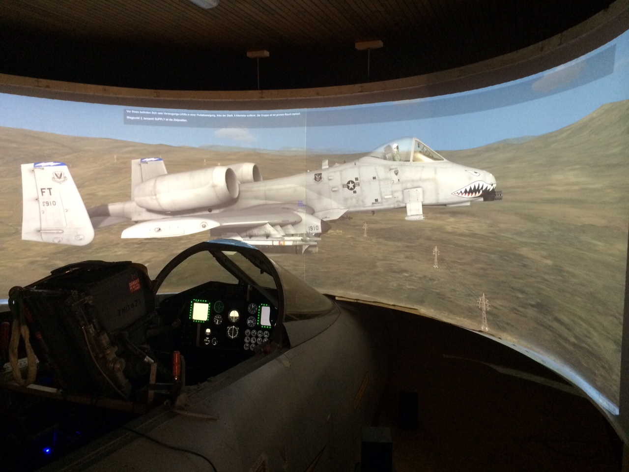
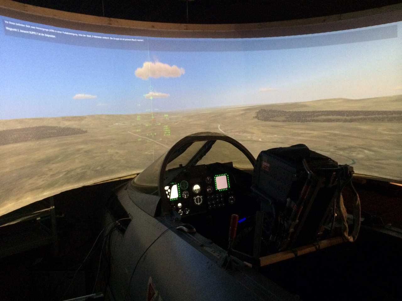
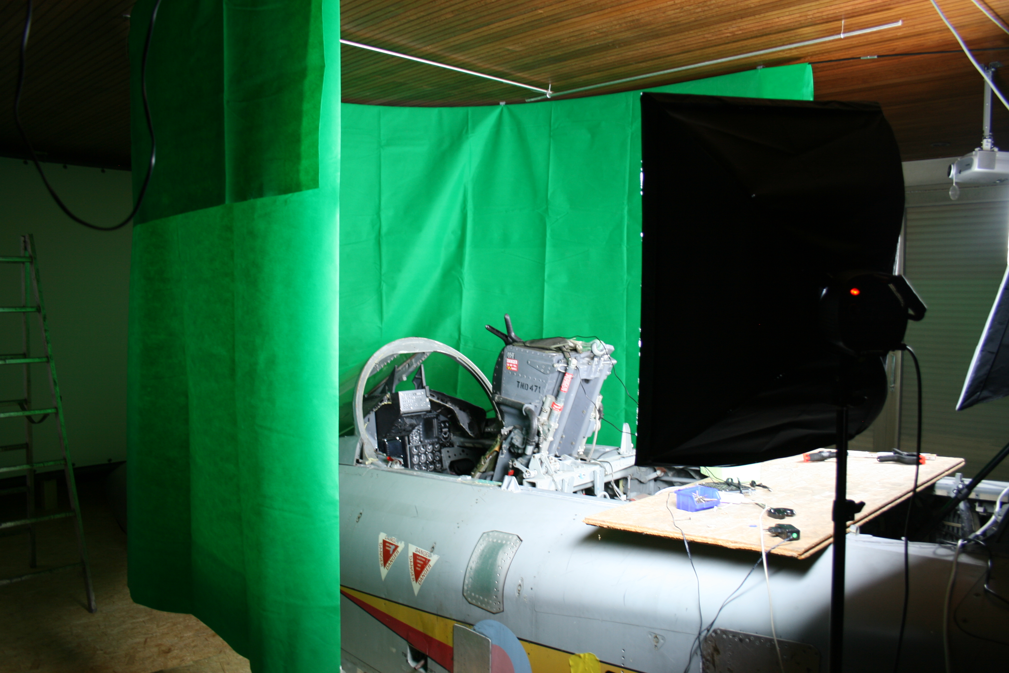
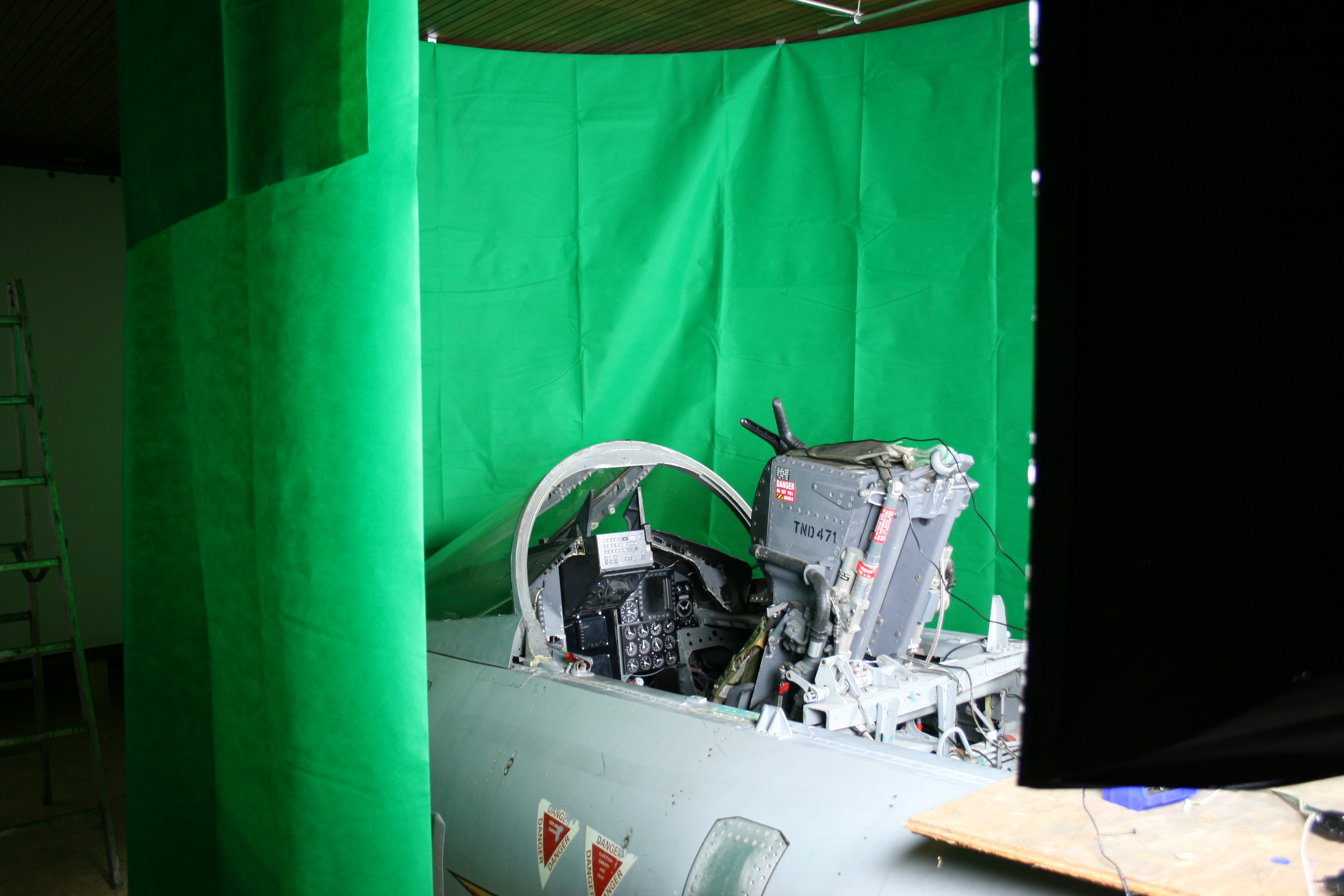
Finally some pics of my current setup: Sorry for not having a perfect fit between the two projections in the middle. Have to readjust it in immersive.
-
Hi Mr Burns, The electronic part I found out myself by internet research. The whole I2C bus things and so on. Then started to make my own pcb's to make a kind off mass production for the needed inputs. At first, I made my own software to communicate between arduino and dcs. But now, using the great DCS BIOS interface, everything is much easier and much more stable. if u want to change to the Arduino side, i recommend u to use this interface. Its easy, either using ethernet or usb seriell, your choice. Hopefully I will find some time to start a new thread about using the I2C bus with the DCS BIOS interface.
-
Sorry for not answering the last weeks. Had some hard days at work. But hopefully i will be able to reply my pms and send the promised arduino code for i2c devices and dcs bios. Btw i love this piece of software !!! But i also did some work on my projector setup. Changed the screen so a smaller size and nearer to the cockpit. And also replaced my three old 1024x768 projectors by two full hd projectors with 3500 lumen. The quality gain is really impressive. Have to send pics tomorrow.
-
Very accurate work! Respect! Keep on going!
-

dcsbios, arduino leonardo and 2 pos switch problem
Gremlin77 replied to shopiK's topic in Home Cockpits
Had problems like you described when i used pins of my mega that were also used by my ethernet shield. Dont know the used pins of leonardo, but i would try to change pins for your switches and retry. Perhaps that helps. -
I will send the arduino sketch these days. If anyone has additional questions, no problem.
-
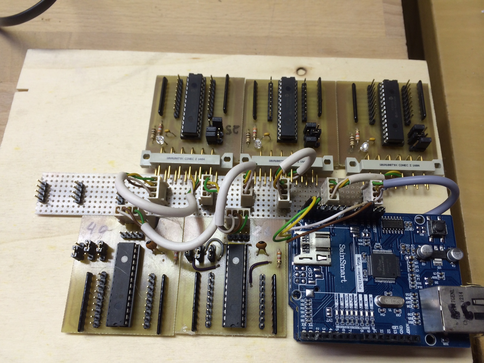
Redesigned the electronic / Software Hi all, Gone a long time since my last post. But I did lot of things. So I now finished all the panel work on my cockpit including redesigning it to the DCSBios software. It's in my opinion the best method to use arduinos with the DCS Software, and, by the way, much better than my badly written c# programs :-) I just made some changes on the Arduino-Software-Part of DCSBios to use my I2C bus system and I divided the whole cockpit into Blocks, so I now use 5 Arduinos connected via Ethernet-Shield. This is how one Block looks like (here one arduino with 5 MCP23016 on the Bus) Each MCP23016 has 16 I/O pins and you can use up to 8 controllers in the Bus, this makes 128 I/Os for one arduino. Will send some pics of the whole cockpit soon.
-
Hi all, I have re-designed my whole cockpit to DCSBIOS. (Gremlins A-10) and it works very well. I redesigned the arduino part of the software to use it with some I2C portexpanders (MCP23016). You can use 8 of these on your I2C bus, and each has 16 I/O pins. So one arduino can use up to 128 Inputs or Outputs on top. For my cockpit I use 5 Arduino Megas with Ethernet Boards to connecting the hardware to the sim. Have finished this way all consoles with all supported functions. If anyone is interested in connecting DCSBIOS to I2C devices, please contact me. Will shortly send some pics in my building thread. Thanks to the DCSBIOS developer, great work!
-
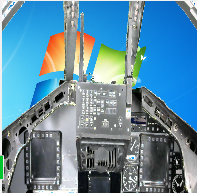
Hi all, so now I have finished the first steps: The two pics show my simple setup for chroma keying. Just a quick one, without removing all the twinkles etc. And here ist the "calculatet" result of the camera picture: I will give this setup a change to more perfectionism..... :thumbup:
-
Hi Guys, sorry for beeing absent for such a long time. Work caught my life....... But I hope that I will be able to show you some progress on my pit the next days. I have ordered an Oculus Rift DK2 a few weeks ago. Now waiting for my baby, got my hands on a DK1. So I thought to mysefl, wouldn't it be great to use this hot thing with my Flight simulator???? But I came across the same problem you all will probably think off: I have spent many hours building up a real cockpit, but with that Rift on I cannot see the damn thing. After thinking some days about it, I came to the result, that I should be possible to add two cams to the rift and mix the cam pic with the DCS view. And let me say: it works!!!!! Step by step: 1: I have two DCS outside views with motion tracking of the Rift (in my case of TrackIR) one for right and one for left eye 2: I have a cam View for left and a cam view for right eye 3: I take the cam views an let a nice little piece of software I wrote in c# calculate all blue coloured parts of the picture to transparent. (Like a bluebox in television) 4. I put the calculated cam pics over the DCS view. Now I have a pic with cam seeing DCS through the transparent parts. 5: Taking the combined views for every eye an apply the rift distortion to it 6: Send the whole sh.. to the rift and.......smile Now I began hanging a nice blue curtain around my cockpit and voila: I see my real cockpit and the DCS view in full stereoscopic 3D in the rift. When I finished this up (bigger curtain is on shipping), I send pictures :-) Hope you will like it!
-
Hi, as named c:\A10 Just create a folder named A10 in your c:\ directory. is my directory for my tools I programmed for DCS an my simulator. Sorry, not able to change this easily.
-
try my tool if you want: http://forums.eagle.ru/showthread.php?t=100704
-
WE WANT PICS!!!!!! please......and welcome to the forum!
-
Awesome!!!! Fantastic work!
-
Final version: download at other thread: http://forums.eagle.ru/showthread.php?t=111834&page=3 - supports up to 4 instrument panels - use the two rotaries to adjust screen capture position - use S1 to chose between small and big steps of the rotaries - use S6 to save If you like it, PLEASE donate (spenden): http://www.737ng-homecockpit.de/ was a lot of work.....
-
any interest for Saitek instrument panel tools
Gremlin77 replied to Gremlin77's topic in Home Cockpits
Final version: ScreenToSaitekV4.0.rar -supports up to 4 instrument panels - use the two rotaries to adjust screen capture position - use S1 to chose between small and big steps of the rotaries - use S6 to save If you like it, PLEASE donate: http://www.737ng-homecockpit.de/ was a lot of work.....:lol: -
Ah okay, I think this trick is not working for multimonitor systems. Think, you need one unused graphic port to use this as a projector output for the fake screen. The trick is, that windows doesn't check this output for an attached Monitor or projector. I only use this trick when I am working on my developer PC, so I don't have to use a second "real" monitor. In my simulator setup, I use a Matrox triple head2go with two projectors for views and the third for exporting CDU, MFD etc.