Duckling
-
Posts
606 -
Joined
-
Last visited
Content Type
Profiles
Forums
Events
Everything posted by Duckling
-
Oops. Sorry, missed your question. Built a new house and been offline most of the time since then yes got three of these still (somehere in the attic) and can send one if still interested. /Gus
-
Hi all. Got 4 remaining PCBs/boards for sale to replace a bricked TM Cougar PCB (or get it usable with Windows 10) see 1st post (updated 220428) in link post below and be sure to read the description AND disclaimer. You are required to flash and config the Arduino Pro Micro with MMJoy2 firmware. I request 10Euro each (my HW cost) and they sends to Europe, shipment and any additional costs/taxes is on the buyer. Payment via paypal. All boards require an Arduino Pro Micro 32u4 5V, 16MHz, get this with soldered pins to avoid additional soldering (this Arduino is compatible with MMJoy2) and a MCP3208 chip (8Channel 12 bit ADC DIP). Rest of components are soldered on the boards. (if interested 'but not yet', you'll find the PCB production Gerber file and additional info in the linked post if you want to create this yourself, it's released as 'free for all'. PM if interested. I'm in Sweden All the best /Gus

-
Now working, at least for my setup, with the TQS. I missed a PCB connection to throttle connector (15 pin 'VGA' connector pin 15 <-> 5V). Updating first post shortly /Gus
-
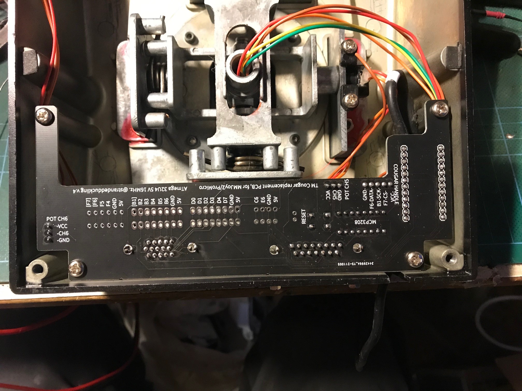
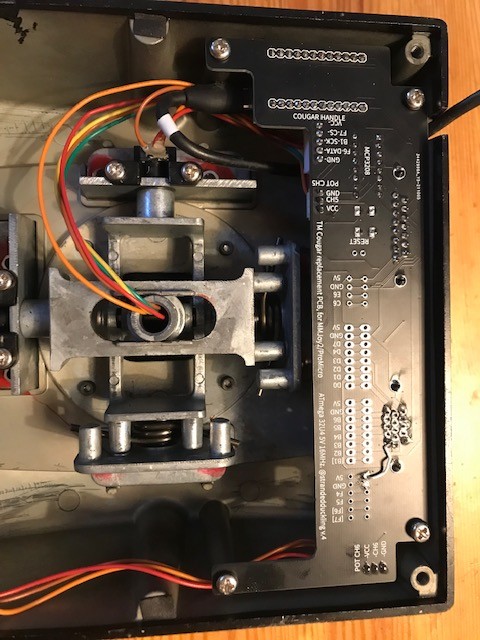
Yes, Version 4 created. soldered it yesterday and installed in my Cougar. As Sukol1_br reminded me of (thanks), win supports 8 axis total per device, with that and the suggestion from aelfweu, I extended the options somewhat. All (almost) of the ports of the ProMicro are now exposed to solder connection A MCP3208 provides 8x12bit A/D ports (2 ports hardwired to the stick, 5 to the TQS/DB15VGA contact and last one to DB15/Rudder. If either TQS or Rudder not required this ports are free for any other use (just connect your wire to the corresponding pin on the board (5V and ground is available on several places on the board. L/R (rudder) brakes connected directly to the ProMicro, 10bit A/D each so all in all 10 prepared axis inputs but user has to choose with 1-8 to use, or define another axis on any other free port to use instead. It has a few glitches: ProMicro USB port connection cable comes VERY close to internal 'pillar' screw mount within the Cougar base. You'll see I hade to trim the contact to get it to fit. There is also the placement /rotation of the boards stick axis port that could have been better. Edit: There's to be some other things I err'd on but with the stated exeptions not yet found :- ) , still early days Currently TM Stick (with axis and buttons) works but only the TQS axis (Throttle/Range,Ant elevation and ministick works (the later remains to be seen if ok), but the buttons is inop. Probably I made some err either in connection, logic or programming the mmjoy2. Currently running MMJOY2[v20160818upd1]. If I understand it right the sticks buttons (working), should be shown working in the button matrix HW view when pushed, but no joy. Defining the the TQS button matrix results in several of the sticks buttons is lost and order is swapped. Any suggestions welcomed All the best /Gus
-
A-10C CDU length and width dimensions needed
Duckling replied to WildBillKelsoe's topic in Home Cockpits
Not sure if that question is directed to me and who 'they' are but I don't have an accurate one, sorry -
low cost solution is a small Neodymium magnet embedded in the front lower side of the cover guard and a reed switch below it will give you that function. Reed switch pass current within the magnetic field. Be sure to place the embedded reed switch with no metal plate between it and the magnet (I used this approach the sense lever position in a real oxy panel) You can find both magnets and reed switches on ebay/elec stores at low cost.
-
Circuit breaker panel question - curiosity only!
Duckling replied to lesthegrngo's topic in Home Cockpits
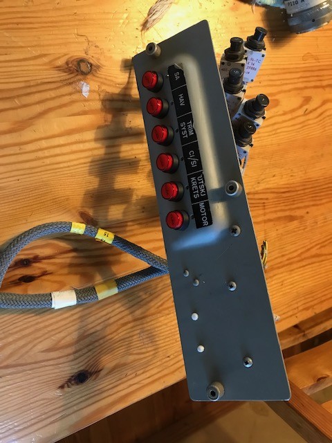
Hi Les One other way is mimic the fuses using momentary LED pushbuttons. Red (in my case) light when 'popped' and not illuminated in 'normal' position. Push the switch to activate the breaker, push to set and so on. (-edit: in game activated breaker will illuminate it of course) IDEC-A A8 Series comes somewhat close to the real size (8mm diameter and the top flange of 10mm), IDEC is not lowcost so pics below shows CH low cost switch replacement selected for cost and real panel (AJ37) hole diameter of 12mm. A bit odd looking but will do. Side/top will be eventually painted in black and engraved (Work ongoing) /Gus IDEC-A-Series_eng-tds.pdf
-
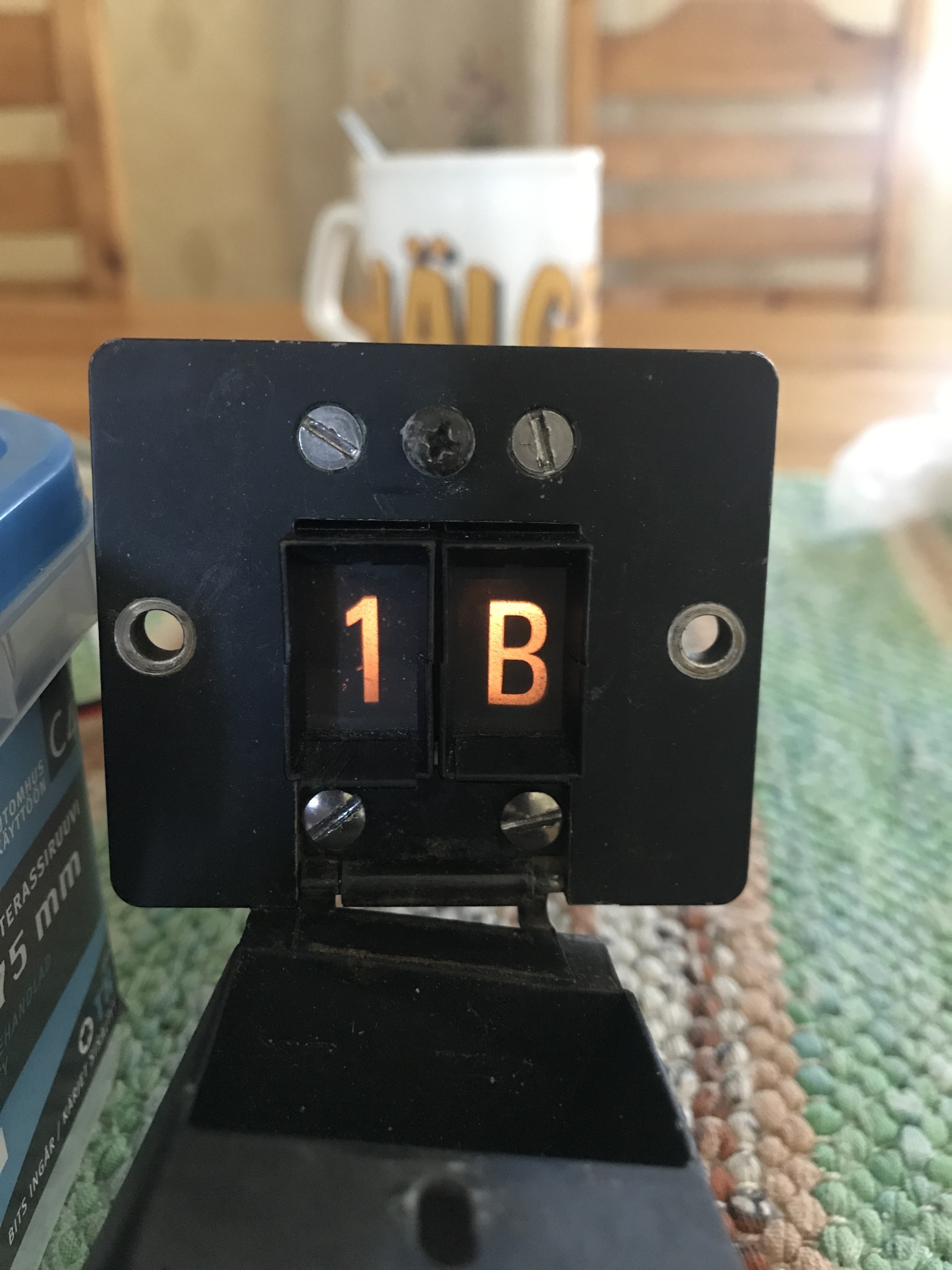
Nerd comment just in case, true size is aprox 9,2 x 5 mm in our DI. Individual digits size vary somewhat (very little) below is part of a lamptest (AJ37 specific digits) so ignore combinations and placement of indicators. /Gus
-
First batch ordered (5 boards) will be as v2 above but no problem to try to expand in another venture just fore the stick base itself. Long vacation and hopfully some rainy days ahead. Can you describe your requirements? Internal or external 'buttonbox'? Or internal with expansion possible to an external box? DCS only? Numbers of intended encoder, switches rotaries etc, Isolation diods at the PCB or on the switchside Type of connection required, via BUS or per each connected switch/encoder etc? Gotta check the prereqs of MMJoy2 max configs also
-
Oooops, totally true and no way for me to save face here ;-) Just scooped up available physical ports and routed'em. WIN limits was nowhere in minds in that time. Thanks for the remainder. Adding an extra device (or embedded HUB) will press the cost to high. First five boards then (minimum batch ordered) will only support either stick/throttle + rudder yaw (or stick + rudder Yaw, L&R Brake) depending on MMjoy config. Lets see how they behave before any decision Huge board yes, and also lot of space to utilize or to cut away to other purpose, wanted to keep it simple since I'll keep my original gimble. Compress the physical space of the PCB would not be an issue, and could be formed to use three of the four existing fastening bolts and cut away but required space (I'll avoid SMD at all cost :- )
-
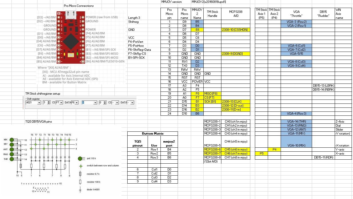
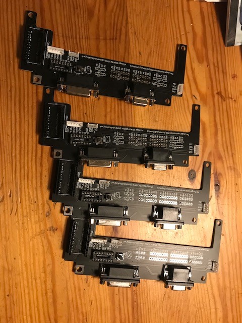
@aelfewolf: CH0-CH7 was (now mostly dedicated to the TQS) 8 x 12bit inputs through the MCP3208 DAC chip connected to the MMjoy2. Rotary encoders is supported by the MMJoy but in this case I haven't checked up on if the 3 remaning unused pins (exposed on the board) provide support but I guess so. @Habu_69: Thanks but remember as stated above, this will not be commercial board, I'll probably will have a few extras due to have to order them in production batch. As long as this project works, I'll upload the gerberfiles here to use for anyone (upload them to a PCB production of choice and you will get the board/boards back for a low cost) Next iteration of the board below: Added the 15pin 'VGA' connector for the Throttle and DB15 std for the rudders, and cleaned up the board a bit. I connected 5 of the 12bits available pins (of the MCP3208 DAC) to the TQS connector (ministick, ANT, Range and the Throttle), 2 pins (12bit) handle the flightstick, and last 12bit goes to to the rudder connection (Yaw). 2 * 10bit (Arduino native resolution) goes to rudders L/R brake. 7 pins used for the TQS button matrix leaving 3 pin unused, these together with VCC and ground exposed as solderpoints on the board (or for a extra pinhead of choice (2.54 pitch) Finally found the the correct pinheads TM use (JST-HE) and ordered a batch, Also ordered 5 PCBs as first batch yesterday, will be a month before next verification/test can be made (hoping for the best) (Ignore the blocks for CH5-6 in the pics, JST-HE will be used and same for the stick handle itself) All the best /Gus
-
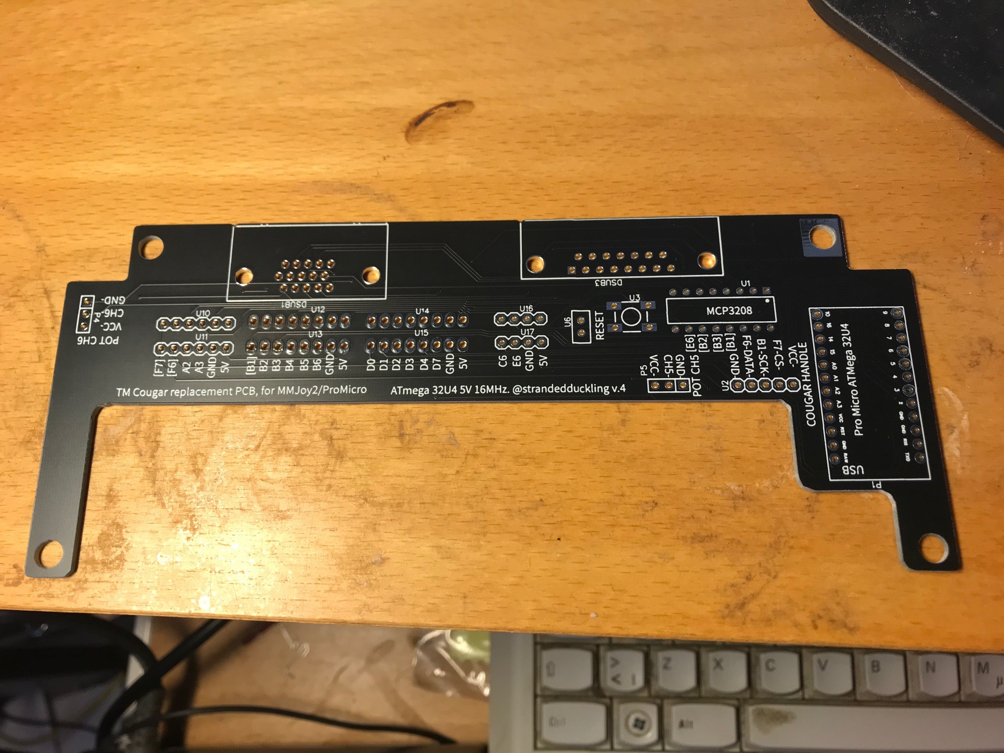
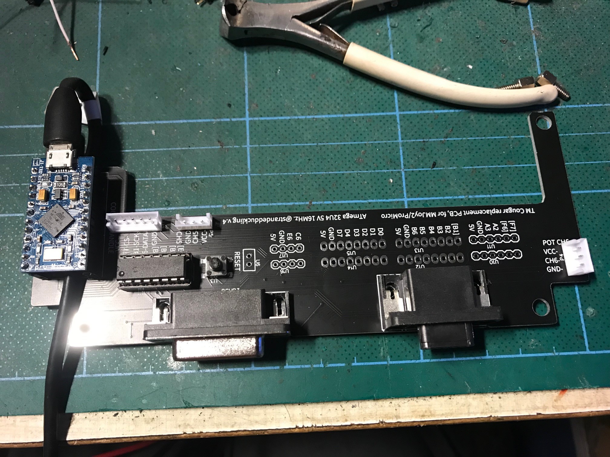
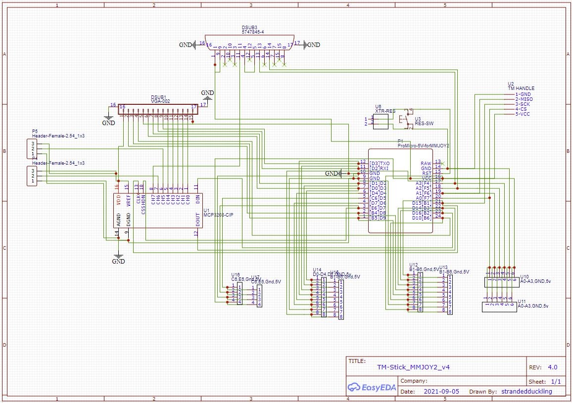
Update 220428: Short description: Drop-In replacement board for Thrustmaster Cougar 5V Stick, to replace bricked original PCB. This converts the Cougar stick to a USB Device using the wonderfull MMJoy2 'application' 12bit resolution 8 axis with a MCP3208 DIP. Provide 8 channels: - Stick 2 axis (pitch, roll) - Throttle/TQS connectors 12bit ADC resolution 5 axis (Throttle, Rng, Ant, Microstick (2 axis) - Rudder (Yaw 12 bit) + left/right Brakes (10 bit) **-> Note that Windows only support 8 axis total per USB device so you have to choose which to use from above options. All ports from the MMJoy2 MicroPro is exposed on the PCB, use these as you like for additional button matrixes, switches and so on i.e. If you not connect the TQS or Rudders, PCB assigned ports/axis are at free for other tasks. The PCB has place for a tactile switch (through hole) and also solderpoints for an external reset switch. PCB will fit a TM Cougar with original Gimbal BOM/Bill of Material excluding the PCB itself are: 1 Arduino MicroPro 32u4 5V 16MHz (this version is MMJoy2 compatible) with a "as long as needed" USB cable 1 MCP3208 DIP (8 Channel, 12bit ADC DIP) 1 Optional (but recommended) 16pin dip socket, for the MCP3208 DIP 1 DB 15 Pin 3 Row Female D-SUB VGA Connector PCB (TQS/Throttle Connector) 1 D-sub Connector Female 15-pin 2-row Right Angle (Rudder connector) 1 JST EH 2.5mm pitch 5-Pin Straight Socket Male Connector (Stick Handle connector) 2 JST EH 2.5mm pitch 3-Pin Straight Socket Male Connectors (Stick pitch/roll pot connectors) 1 Short cable to connect TQS connector pin 15 to 5V on the PCB 2 12pin female pinheader 1 6x6 Tactile Momentary Push Micro Switch (as low as possible (reset switch for the ProMicro) (soldering skill IS mandatory) To get it working: Solder the PCB components, *note the direction of the components/sockets. Flash the ProMicro with MMJoy2 (I used version v20160818upd1) Replace the original TMCougar PCB with this board. Verify the USB Device is visible in windows Start MMJoySetup.exe (preferable v20160818upd1 if you'll use my provided setupfile (For stick + throttle) Select your MMJoy device from "Device list and configuration" Click "Load sets from file" , select the "TMCougar_220423_MMjoy2_v20160818upd1.mmjoy" Click "Save Set to device" Restart, Calibrate your axis under windows game devices and verify your buttons. This should get you running, The "TMCougar_220423_MMjoy2_v20160818upd1.mmjoy" is my working setup. For how to use/config/extend the MMJoy2 configuration, see https://github.com/MMjoy/mmjoy_en/wiki MMJoy ports assigned ON the PCB (see the wiki for pin numbering schema) Cougar Stick handle: F6, F7 (3x4021 shift registers) Button Matrix Rows: B4, B5, B6 Button Matrix Columns: D0, D1,D2,D3 Joystick Axes (12 bit) E6 (8 Channels), B1 (Clk), The channel 8 is "Rudder yaw (L/R)" Rudder Brakes (L/R) F4, F5 (10 bit) Disclaimer: English is not my native language, please ignore bad spelling/grammar. I have no intent to further produce and sell these boards (apart from the four extra I currently have). I will upload the PCB Gerber production file to this post shortly plus some extra info. You can send the Gerberfile to a PCB production company to have the PCBs created, i use https://jlcpcb.com/ but it's up to you. PCB Created with EasyEda PCB gerberfile free to use for anyone, no exceptions. Provided as it is, with NO warranty or stated support from my side, i.e. it's on your own risk. Apart from the TQS, I have not tested the boards every ports but so no reason why they shouldn't work. And, pay attention not to damage the cabling. There are several posts here and on other sites how to replace the Cougar stick PCB. All the best Gus **** Hi Guys Thought I share some info of an ongoing project. ***** Edit: Just to avoid misunderstandings. This board is intended as a drop-in replacement for a bricked original TM Cougar PCB. It utilize a lowcost Arduino Pro Micro flashed with MMJOY2 firmware (MMJOY2, by Mega_Mozg, https://simhq.com/forum/ubbthreads.php/topics/3899105/mmjoy-mmjoy2-set-your-own-usb-controller-with-a-cheap-arduino). (there is a subforum here in ED forum as well). All the fancy stuff and option provided by MMJoy2 is taken place within that firmware/control, my intention is just to adopt it to easy use for an old Cougar in need of life sustaining actions. The MMjoy2 provides built in support for the shiftregisters within the Cougar stick (CD 4021B in my case). ******* I digged up my old dusty Cougar to use again after many years. Now in W10 environment and failed to get it working, was visible in device manager as a HID devices but all the tips and tricks I found failed. Even reinstalled both W98 and XP on an old PC and attempt to config the stick there failed. Finally reset the firmware and that was the last sign of life from it. Pinged TM Support with with S/N, version etc and received a query to further document the quiz and thought the better of it. A new original PCB would be high (rather) cost and still force me back to the driver issues. I used URI-BAs TQS mod for Gameport to USB using a small Arduino Micro Pro, (Throttle was the primary need) and worked right of (Thanks URI). After sometime I read up on MMJoy2 (absolutely fantastic software) to get the stick back in action using another Micro Pro and an lab/brakeout board. The support for the TM embedded shift registers in the handle, made the conversion a doable task. Cleaned the original POTs and they came up quit nice with minimal noise so I'll keep them. Obviously support for Target and other TM Software is gone but got MMJOY SW will make up for it if I put these into more advanced use. Anyway, I'm left with one extra external adapter per device, could be remolded to fit inside each base but that would still leave option for rudder input (that huge DB25 DB15) to be connected some other way. Now started to create a drop-in PCB replacement board again based on Arduino Micro Pro and MMJoy2 to enable to reuse all existing cabling inside and also provide some extra 12bit DAC connections and connection points for a button matrix expansion. If this goes well, it will not be a commercial product, so intention is just to provide the gerberfiles for the PCB itself with some additional info. Below v1 of the PCB, just for the stick, not the correct pinheads here. More to come (hopefully) (please ignore bad spelling/grammar etc, I'm not native English speaking and doing my best here), there bound to be errors in labeling and info but I'll do my best to tidy them up along the way) Cheers /Gus TMCougar_220423_MMjoy2_v20160818upd1.mmjoy Gerber_PCB_MMjoy2_Cougar_Stick_v4.zip
-
Thank you Sokol1, but unless I misunderstood something, there is no info regarding the quiz about the pinheads model info in the link. I guess Guillemot used either proprietary (unlikely) pinheads or that the model gone from std business years ago, still hope though. Getting hold of correct one would ease the swap. Using std pinheads works but better if the real ones can be located All the best /Gus
-
- Anyone that can point me to the correct version model/manufacturer for the pinheads on the original TM PCB? se pics, I searched Farnell, digikey and some local stores but failed to find the correct one EDIT: Found it (I think) "JST-EH" / https://www.jst-mfg.com/product/pdf/eng/eEH.pdf I see now that this post should been in the 'Thrustmaster' subtopic. Sorry for that. I deleted the bulk of here it and will repost in the correct place. Cheers Gus
-
Hi Sprool. Some info that might be helpful but not directly on target. That Rotary selector is controllable from LUA in DCS export environment. Sending a GetDevice(2):performClickableAction(3302, n), where "n" is a decimal value in range {0, 0.1, 0.2, 0,3.. .. 0.9, 1} (11 steps) will set that selector to a fixed position. Using either a Rotary or Encoder "switch" and a add-on software as DCS:BIOS, Oakes script, Helios etc can send controls to DCS, but for the alternative keybindings I'm kinda (really) lost. I'm using Oakes scripts for this due to demands but DCS:BIOS would be my first option for a generic setup otherwise. If there's a way to bind a LUA command to a keybind there is a way forward. Looking in the AJS37 module clickabledata.lua, I can't find choice for step up/step down values though. A Rotary (with 'break before make' 12 pos selector with individual electric connections per position), is then probably the easiest way but eats input ports, An Encoder takes only two input ports, but requires additional support by both hardware and configuration in the application. /Gus
-
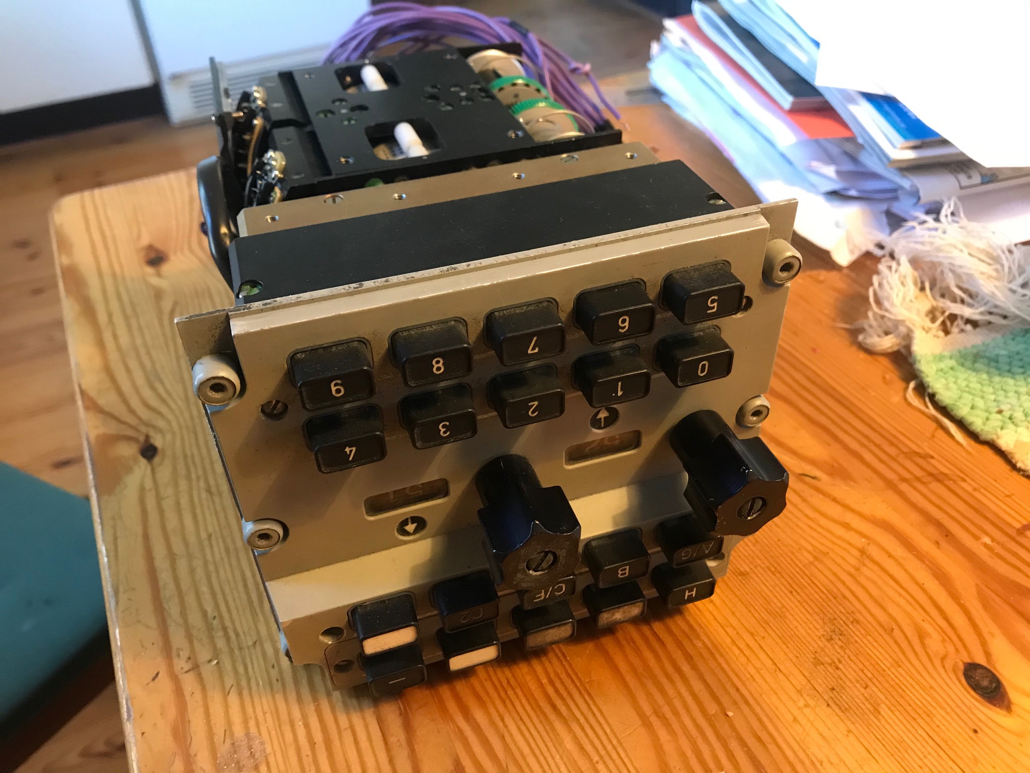
Thanks The glory of that goes to SAAB and the mechanic genius constructor of it. (Freq settings of the actual real thing on the "5-9" knobs setting is actual an individual 16 bit Ochtagol magnectic encoding of each 'embedded shaft'.. (will not be reused) and the backlight internal cabling (not seen in the Pics) is only reachable by removing all mechanics and I sincerely trying to avoid that. Like opening a pandoras box For the Base and Group commands as far I remember the result of performClickableAction, with an Argument value of "1" or "-1" steps these up/down one at the time, they are reversed to each other (One step up with "1" the other one step down, if I remember correct . I can (could) force a 'multistep' action by a larger integer. Since the action in both real and virtual panel is a limited (1 <-> Max). In theory that actually work as a oddie defined workaround (. Place physical contoller in lowest position , stepping down Virtual pit controller all the way to position "1" and a few more and the up again but there is now way to find if the interface missed a step vs DCS or not.
-
Hi Outbaxx You ahead of me here, I've had same issues on a few of the listed above on early testing but most not touched yet. My environment is Oakes scripts and not DCS:BIOS, even if I use the LUA console for verification of LUA code I'm currently on World O.B. and the device ID or Argument may differ between versions (haven't verified current std World release yet) but I do found (read) that DCS:BIOS Branch code addresses FR22 as DeviceID 34 (within ajs37.lua latest) instead of 31 as in my version of O.B clickabledata.lua. Can't say if that point to the couse in your case but worth checking I have the FR22 running happily on all but the Group and Base 'wheels' controls (those works but currently on on a step up/down basis) FR22 Device ID 31. SIOC Code below but almost the same. (31, 210, 1 -> Sending a "1" to DiviceID31, Argument 3210 for the "knob 0"(code adds the base 3000 to each argument in my case)) LUA function pushes integer "1" to activate the buttons and "0" to release. (The disclamer is that if an additional "release state" follow the activation of the control, is required of the control I haven't found and verified that yet). It do activate the selected knob in the virtual cockpit and release when other is pushed just as in the real FR22) -- device ["FR22"]: Device 31 [20] = {TwoPositionSwitch, 31, 210, 1}, -- "Flight 0" needs release command [21] = {TwoPositionSwitch, 31, 211, 1}, -- "Flight 1" -- " -- [22] = {TwoPositionSwitch, 31, 212, 1}, -- "Flight 2" -- " -- [23] = {TwoPositionSwitch, 31, 213, 1}, -- "Flight 3" -- " -- [24] = {TwoPositionSwitch, 31, 214, 1}, -- "Flight 4" -- " -- [25] = {TwoPositionSwitch, 31, 215, 1}, -- "Flight 5" -- " -- [26] = {TwoPositionSwitch, 31, 216, 1}, -- "Flight 6" -- " -- [27] = {TwoPositionSwitch, 31, 217, 1}, -- "Flight 7" -- " -- [28] = {TwoPositionSwitch, 31, 218, 1}, -- "Flight 8" -- " -- [29] = {TwoPositionSwitch, 31, 219, 1}, -- "Flight 9" -- " -- [30] = {TwoPositionSwitch, 31, 200, 1}, -- "Channel H" -- " -- [31] = {TwoPositionSwitch, 31, 201, 1}, -- "Special 1" -- " -- [32] = {TwoPositionSwitch, 31, 202, 1}, -- "Special 2" -- " -- [33] = {TwoPositionSwitch, 31, 203, 1}, -- "Special 3" -- " -- [34] = {TwoPositionSwitch, 31, 204, 1}, -- "Minus" -- " -- [35] = {TwoPositionSwitch, 31, 205, 1}, -- "Channel A/G" -- " -- [36] = {TwoPositionSwitch, 31, 206, 1}, -- "Channel B" -- " -- [37] = {TwoPositionSwitch, 31, 207, 1}, -- "Channel C/F" -- " -- [38] = {TwoPositionSwitch, 31, 208, 1}, -- "Channel C2" -- " -- [39] = {TwoPositionSwitch, 31, 209, 1}, -- "Channel D/E" -- " -- [40] = {SUL37_MULTIPOS_SWITCH, 31, 307}, -- "Group Selector" -- " -- [41] = {SUL37_MULTIPOS_SWITCH, 31, 230}, -- "Base Selector" -- " -- Bottom two are currently INOP. Pics on onging work on the real FR22, The panel/knob backlighting is a nightmare ... Cheers Gus
-
BlackLibrary, thank you. Lost myself within your linked documentation for a while (or rather a day or two and still just scratched the surface ..), just the comprehensive ajs37.lua is a real timesaver for our ongoing work. Small donation inbound Cheers Gus
-
A beautiful approach by Blue73, thanks for pointing it out, missed that until now, could really be handy in other projects but not directly applicable in this case due to use of SIOC/IOCards. DCS:BIOS is not ruled out yet, will likely be cases I can't solve through Oakes scripts and LUA so option is valid. The method is somewhat like a french (speaking) guy made for IOCards to trigger a resync of active state of inputs to update SIOC from input states to sync to connected SIMs. I'll hook it here just in case some other SIOC nerd find it a future search, in French though; -). In short that update the SIM virtual cockpit from physical settings of switches etc. And I haven't given up hope yet to either to find a solution on read status of the panel switches etc in the virtual cockpit or that controls will be added in future release for those that's missing today. Long journey ahead still for us There are some LUA functions visible/addressable per panels such as 'GetCommand' etc that might be a way forward but don't know what they do or why, played around with them but no success there (I got a long way to walk on the LUA path still) Cheers Gus Pb reload SIOC.pdf
-
Thanks outbaxx I'll check it out (only fast scan through it yet) Cheers Gus
-
Nopp, no joy yet .. and my LUA skill is far from top notch. (Tested just in case with suggested but failed) Testing ongoing. Digged into the metateble of the device 31 (in this case) and the function "get_argument_data" isn't listed there so I guess there no option to get it status that way. 3307 on devID 31 AJS37 is FR22's Group Selector knob, and the definitions of type, function, and coding differs for that same differs between HB, DCS BIOS HUB and the DCS-BIOS branch code for AJS37. Reused some code from above did mange to get the CK37 NAV and Destination display Digits and control some other multipos switches so not totally stranded yet. Going straight through LUA console here just to see what I manage to grab from the generic export environment but no luck on just this 'knob' yet. Cheers edit: @Savvy , If you planed for but haven't used DSC:BIOS yet, I'd say go for it. Can look a bit overwhelming at first but both code and documentation are great and cost for the Aurdinos is almost negligable
-
Hi I'll try avoid to doublepost entries in several threads so just a link below for background info: https://forums.eagle.ru/topic/264334-dcs-bios-lua-console-read-cockpit-deviceidargument-values-for-dcsajs37/?tab=comments#comment-4594773 - Is there a way/method/syntax to find out the LUA Argument value of some switches on panels outside the mainpanel? Going through same method I used in the A-10 Module that worked ok gives me 'NIL' in response here in the AJS37. I can set a value through LUA but fail to extract same or any other besides those on Device(0). Below response is through LUA Console in DCS:BIOS HUB (I'll get the same response using DCS Witchcraft Console in older version of DCS:BIOS as example: returnValue = GetDevice(31):get_argument_value(3307) return returnvalue The response is: Response:runtime error 1 | [string "Lua Console Snippet"]:2: attempt to call mathod 'get_argument_value' (a nil value) Reason for this is to find a way to sync the virtual cockpit settings to the 'switches' in the physical cockpit. (I can't find a way to set rotaries/multipos switches, FR22 group and base selectors etc to a fixed position in DCS. Only see the step-up/down keybindings) Hoping for some guidence in either how to grab the device()-Argument-values or to set a fixed position setting through LUA Someone here that can help out? All the best Gus
-
Thank you Savvy,
-
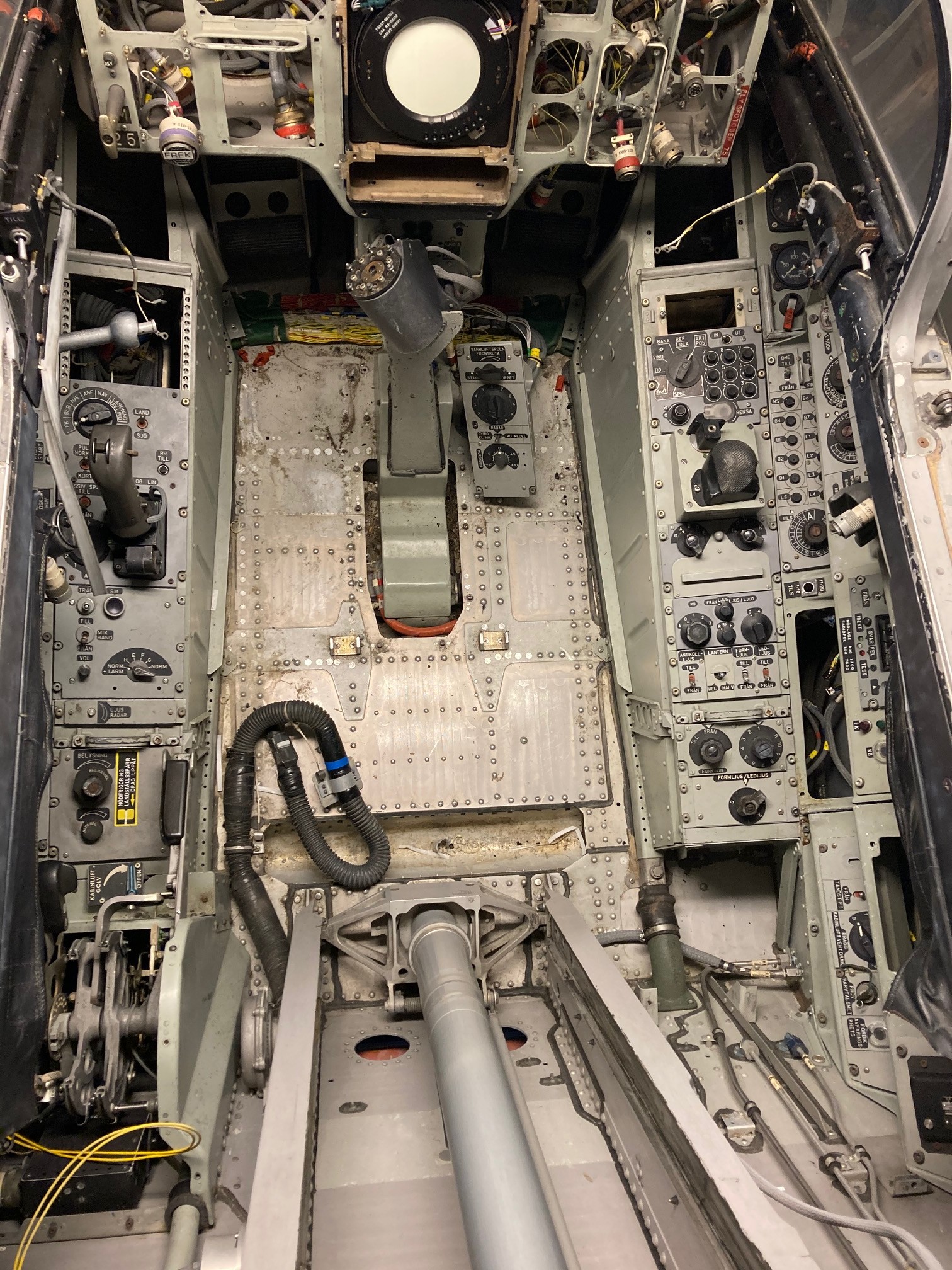
Hi Any help or idea appreciated. Should I be able to extract cockpit data via the DCS:BIOS Console using the syntax above? Do anyone here that have both DCS:AJS37 module and DCS:BIOS help out making that simple test described above, it would help greatly to easy troubleshoot this. (I do see applicable cockpit data active in DCS:BIOS Control reference so the connection is alive and question is in the LUA Console to query device/arguments) Right now I can't say for sure if it's my current config that fails, the LUA (HUB Version) Console that have issues with me, my syntax or if DCS:AJS37 Module that must be treated different some how. In my early A-10 simpit, I had the imports working from DCS (but there running older version of DCS:BIOS with Oakes scripts and SIOC) Work in progress is converting a real AJ37 Viggen to a simulator to join our existing J35 and J39 Sims at https://en.flygmuseum.com/ (ESOW Sweden) Existing MIL SIMs running X-Plane but this one is targeted (Of Couse) to run DCS, though the option to run it on X-Plane/FS2020/Prepar3D must be possible. That pushes us away from the 'simple' approach to use DCS:BIOS/Arduino and target is to use Oakes scripts here and IOCards/SIOC. Status right now is that the cabin is cut behind the canopy (so front of those mighty airtakes remains) Work on converting the panels to simulator use is almost completed. Gauges, radar and a lot other remain. Not exactly a Home Cockpit but essential not far from it. Early stages yet but if anyone like us to have a buildthread here to follow our progress, say the word All the best Gus
-
I'm searching for a working method to read the status of a switch on a device other then Mainpanel/(0). Not sure if this 'should' work or my attempt fails to using lack of understanding LUA/DCS? I set a switch via LUA console with no issues: GetDevice(31):performClickableAction(3307, 1) But when trying to read the same argument value by issuing: returnValue = GetDevice(31):get_argument_value(3307) return returnvalue The response is: Response:runtime error 1 | [string "Lua Console Snippet"]:2: attempt to call mathod 'get_argument_value' (a nil value) Anyone that can guide me to working command? Best Gus