
Hansolo
-
Posts
1775 -
Joined
-
Last visited
-
Days Won
1
Content Type
Profiles
Forums
Events
Posts posted by Hansolo
-
-
Agreed. The dial moved same direction as the knob. The knob has a small pit IIRCC which forces the dial to move
Cheers
Solo

-
Jesus this is sad news, John. Thanks for letting us know. I worked in parallel with Wayne back when both of us where build a prototype of Deadmans cockpit plans. A very open and helpfull gentleman.
Rest in peace Wayne

-
Hi Markus,
If you have a rotary switch with 20 positions each with their individual pins you can use this
const byte uhfPresetSelPins[21] = {PIN_0, PIN_1, PIN_2, PIN_3, PIN_4, PIN_5, PIN_6, PIN_7, PIN_8, PIN_9, PIN_10, PIN_11, PIN_12, PIN_13, PIN_14, PIN_15, PIN_16, PIN_17, PIN_18, PIN_19, PIN_20};
DcsBios::SwitchMultiPos uhfPresetSel("UHF_PRESET_SEL", uhfPresetSelPins, 21);
If you turn the switch from position 3 to position 4 then on SOCAT you should be able to see
UHF_PRESET_SEL 4
If you turn it further to position 5 SOCAT should show you following;
UHF_PRESET_SEL 5
Note that this is being send a plain text
Similar to this example
Now in the AN/ARC-164 example I didn't have a 20 position switch with individual pins for each position. Therefore by using sendDcsBiosMessage I can send the same plain text over SOCAT.
In my example I am looking at pin 29-22 for the combination from the preset selector. If pins 29-22 read the following B11111001, the the position is preset 3. If DCS is at another preset then using sendDcsBiosMessage the message to DCS to set preset no 3 with this code;
 if ( Preset() == 3){
   sendDcsBiosMessage("UHF_PRESET_SEL", "3");
On SOCAT you will see;
UHF_PRESET_SEL 3
which tells DCS to set preset no 3.
Hope this explains it a little bit.
Cheers
Hans
-
Hi Markus,
I haven't looked at it but you could do something similar as I did for the AN/ARC-164;
Under presets I derive the position based greycode (IIRCC).
Cheers
Hans
-
Beautiful build Sir. Very nice looking
-
Hi Markus,
I am quite certain this is the one; https://www.dropbox.com/s/izmxojksfrm4ros/Timer-master.rar?dl=0
Cheers
Hans
-
Awesome work as always Anton

-
Awesome job Anton. Looks very good indeed sir. Very frustrating the force sensing couldn't work though.
Cheers Hans
-
The Anti-collision light switch, anti-skid and the 4x SAS switches are magnetic held toogle switches. When applying voltage (originally 28VDC but 12VDC also works) the bat will stay in ON position once manually activated. You can force it back into OFF position by toggling in the other direction.
If you remove voltage to the coil they will automatically flip back into OFF position.Here is a few older YT I did with them
Cheers Solo
-
 4
4
-
-
Jesus you have come a long way Anton. Awesome looking MFCD's sir. Best ones I have seen
And the CMSC is very good. Looking forward to seeing more.
Cheers
Hans
-
Awesome work sir
-
Mr.Burns, try and look at this; https://easyeda.com/qrethus/arduino-nano-and-max487-chip-with-female-rj45-connector
I don't know who did it but there is a good chance he is here on the forum.
Alternatively talk to Tekkx. He might still be doing his breakout boards;
In his signature there is a link for his hardware solution.
If you want to DIY then I suggest using the prototype PCB I used in the opening post; https://www.ebay.com/itm/Prototype-PCB-8-5-x-20cm-Universal-Matrix-Printed-Circuit-Board-Arduino-AVR/402615276324?_trkparms=aid%3D111001%26algo%3DREC.SEED%26ao%3D1%26asc%3D20160908105057%26meid%3D3e96f2c703cc4326b9c3c8210869fd83%26pid%3D100675%26rk%3D2%26rkt%3D15%26mehot%3Dnone%26sd%3D124513653639%26itm%3D402615276324%26pmt%3D1%26noa%3D1%26pg%3D2380057&_trksid=p2380057.c100675.m4236&_trkparms=pageci%3A108f0def-9a25-11eb-9356-a6bbe5552638|parentrq%3Abce6f0351780a7b21ce9e076fff7f5ce|iid%3A1
That way you don't have to solder directly on the pins for the MAX487 socket.
cheers
Solo
-
1
-
-
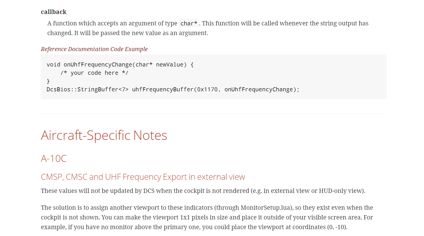
Not sure what module you are running but for the A-10C you need to have a viewport for the CMSP, CMSC and UHF. E.g. you need to export it to you monitor first, it doesn't have to be large and IIRCC it doesn't have to be visible e.g. you can export it outside your visible screen area. Below screen dump is from the original manual. Granted may have changed.
Cheers
Solo
-
The way I have seen on-on-on is by wiring a 2-pole 3 position switch like this;
https://sensing.honeywell.com/2TL1-12-toggle-switches
In this way:

Cheers
Hans
-
You have me slightly confused here. In the original post you use the Nano as Slave, but in post #5 you have the push button attached to the Mega? The Mega running as Master cannot hold any other code than just the Master code.
DCS-BIOS makes internal pull-up when you define a switch. If you have loaded the correct Master code to the Mega then it doesn't have any switches thus you do not have any internal pull up.
It looks like you are missing the end backet in the Nano code. Should be this:
DcsBios::Switch2Pos masterCautionResetSw("MASTER_CAUTION_RESET_SW", 8);Instead of this:
DcsBios::Switch2Pos masterCautionResetSw("MASTER_CAUTION_RESET_SW", 8;Cheers
Hans
-
However, there is something strange going on. Some LEDs need the pinMode command, some don't.
If you are talking about ;
int RedLed = 16;
versus
DcsBios::LED aoaIndexerHigh(0x1012, 0x1000, 4);
Then that shouldn't be too strange.
The former is one you have defined yourself. DCS-BIOS has absolutely no knowledge of this whatsoever. As DCS-BIOS have no knowledge about it, it cannot define it to the Arduino IDE. Therefore you need to use the pinMode command, else the Arduino IDE doesn't know what to do about it. It could just have been a variable you wanted to use for something, similar to what I have done here for the frequencies of the AN/ARC-186 radio;
//Variables
int Freq1_DCS = 0;  //Initial value set for 3
int Freq2_DCS = 0;  //Initial value set for 0
int Freq3_DCS = 0;  //Initial value set for 0
int Freq4_DCS = 0;  //Initial value set for .00
int Mode_DCS = 0;   //Initial value set for OFF
int Preset_DCS = 0; //Initial value set for 1
The latter is using DcsBios::LED which is a defined function that already sets the pin as an output, which it will let Arduino IDE know. You can actually see this in the Leds.h file of the DCS-BIOS Library (only partly shown here);
public:
LED(unsigned int address, unsigned int mask, char pin) : Int16Buffer(address), mask(mask), pin(pin) {
pinMode(pin, OUTPUT);
Cheers
Solo
-
Outstanding work as always Calum :worthy:
Cheers
Hans
-
Have you tried to add this to the void setup?
pinMode(RedLed, OUTPUT);
cheers
Solo
-
Boltz, I think Ian described this earlier on.
It took me a bit of time to find it;
https://forums.eagle.ru/showpost.php?p=2925060&postcount=458
Cheers
Hans
-
OMG that looks so good Calum :worthy::worthy::worthy:
You should become a professional pit builder :thumbup: That AN/ARC-186 is a particular nice piece of work sir. Very glad to see your progress :thumbup:
Cheers
Hans
-
Also try commenting out all LED lines but the one to pin 13 and see if it works then.
If it does, uncomment each line until it stops working.
Sound like very good advise.
I'm running 17 leds in each pinout of the nano, leaving D2 for the MAX487 chip.
Depending on which LED's your are using you may very well be overloading the Arduino's. I think I am using 30mA LED's but may be mistaken. Yes max load on a digital output is 40mA but the max load on the microcontroller itself is just 200mA;
Thought it was a power supply problem, but although sending mega's 5V through VIN and connecting the nano to the PC, it keeps doing that.The input range on the VIN is 6-12V because it runs through a voltage regulator. If you use the Mega's 5V pin (output) then you need to attach it the the Nano's 5V pin as well to bypass the voltage regulator. Otherwise you may very well run the Nano at too low voltage. A 5V regulator needs a little head to be able to maintain 5V, hence the 6-12V input voltage
IIRCC the USB is bypassing the voltage regulator which may be why it works via USB and not over RS485.
Cheers
Solo
-
in DCS-BIOS DOC i found this 2 codes for F-16 Master Caution button & LED
/* Declare a Master Caution Reset button on pin 10 */
DcsBios::Switch2Pos masterCaution("MASTER_CAUTION", 10);
/* Make the LED connected to pin 13 into a Master Caution Light */
DcsBios::LED masterCaution(0x4400, 0x8000, 13);
But if i insert both in my IDE i get the error that masterCaution function is doubled defined...
WHY?
Because they are used twice;
/* Declare a Master Caution Reset button on pin 10 */
DcsBios::Switch2Pos [b]masterCaution[/b]("MASTER_CAUTION", 10);
/* Make the LED connected to pin 13 into a Master Caution Light */
DcsBios::LED [b]masterCaution[/b](0x4400, 0x8000, 13);
Rename one of them e.g.
/* Declare a Master Caution Reset button on pin 10 */
DcsBios::Switch2Pos masterCaution("MASTER_CAUTION", 10);
/* Make the LED connected to pin 13 into a Master Caution Light */
DcsBios::LED masterCaution[b]light[/b](0x4400, 0x8000, 13);
You should be good.
The Control reference I have says the F-16's master caution light is:DcsBios::LED lightMasterCaution(0x4476, 0x0080, PIN);
Your reference is probably for DCS-BIOS hub version
cheers
Hans
-
hi, I wanted to put the led for AA and AG but it gives me the following error, where am I wrong?
UFC_F18_amido:44:26: error: conflicting declaration 'DcsBios::LED masterModeAg'
DcsBios::LED masterModeAg(0x740c, 0x1000, 25);
^
C:\Users\nicola\Documents\Arduino\1\UFC_F18_amido\UFC_F18_amido.ino:43:21: note: previous declaration as 'DcsBios::Switch2Pos masterModeAg'
DcsBios::Switch2Pos masterModeAg("MASTER_MODE_AG", 25);
^~~~~~~~~~~~
exit status 1
conflicting declaration 'DcsBios::LED masterModeAg'
In the above you have masterModeAg appearing twice AND you are using the same pin number for both input and output.
Try and rename the LED's to;
DcsBios::LED masterModeAa_(0x740c, 0x0800, 23);
DcsBios::LED masterModeAg_(0x740c, 0x1000, 22);
And see if that works for you
Cheers
Hans
-
You probably have to ask Ian the father of DCS-BIOS (https://forums.eagle.ru/member.php?u=95995) these questions, because they seem more into how the 'mechanics' in the core code works of which I have no knowledge. This thread is meant as an aid into getting it to work.
Cheers
Hans
.jpg.f0e16001e786493632708083e18e6b12.jpg)

MacFevre pit parts on Ebay
in For Sale
Posted · Edited by Hansolo
Hello gents,
Some of you may know, last year we lost a fellow dedicated pitbuilder MacFevre a.k.a. Wayne. Equally dedicated pitbuilder Warhog wrote this;
Now his wife Kristine is selling he pit parts which can be found here on Ebay; https://www.ebay.com/sch/krislef82/m.html_nkw=&_armrs=1&_ipg=&_from=
If you see anything you like please make a bid and assist her in move back to Illinois.
Thanks
Solo