Boltz
-
Posts
476 -
Joined
-
Last visited
-
Days Won
1
Content Type
Profiles
Forums
Events
Everything posted by Boltz
-
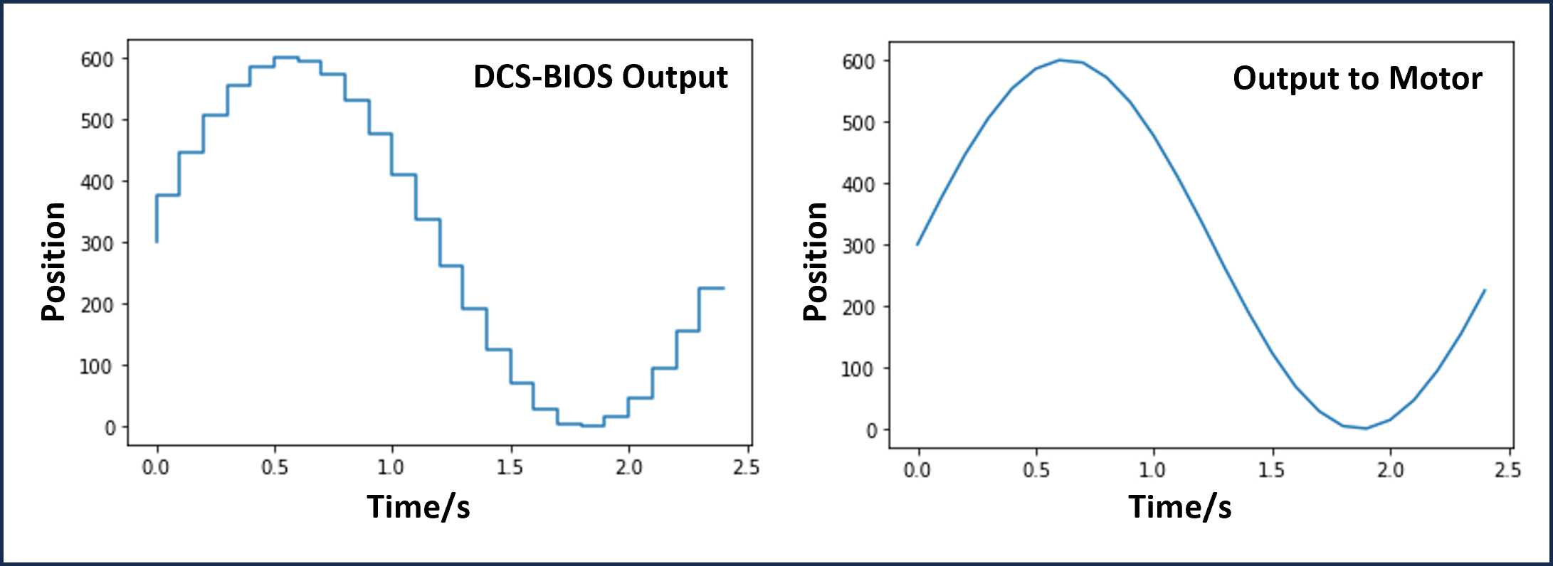
Well 2 years later and I finally got some time to work on the pit again. Trying to find some small weekend projects to do indoors. Got some code written for the X27 family of stepper motors. The SwitecX25 library gives smooth movement if allowing the motor to accelerate up to speed but is not useable for a constant data stream such as with DCS. The motion will end up very "jerky" as the motor attempts to move at full speed to each new position. Instead I am calculating a speed before every move giving very smooth motion even with very low update frequency. Results in a smoothing of stepper position and removes the jerking motion, see picture below. Only my PC graphics card appears to have died so can't test with DCS now but I can create a data stream with Python to send to the Arduino. Results are very nice. If it works well with DCS then it will be worth completing and likely as a new library.

-
Thank you. Makes sense to have it both ways. Certainly going to go with that for the next one
-
Does the real lever need to be pulled when moving both ways, Up -> Down and Down -> Up? My notes say it's only Up -> Down but I can't remember the source so no idea if that's accurate. I need to redesign my version to fit into a new instrument panel. Calum
-
So sad to hear this. I have good memories of our discussions of pit building. Rest in peace Wayne
-
Hi Deadmeat. Yes I added that functionality. From my research it should be pull-to-turn between OFF and STBY, both ways. I need to change out the alu gate plate on my one. I've currently got it only pull-to-turn when moving one way - this is incorrect.
-
Thank you both for the suggestions. I haven't used the LedDisplay library but I'm looking at it now. The bottom row of displays are similar to HCMS-297x but for dimming the top line I think external PWM circuit is needed. Those displays are the SLG2016 and only have a Blank pin for dimming. Anton, that CMSP looks great. The external PWM circuit should give the best results for those displays. Hadn't heard of the Mega Mini before, having that many IO pins in the small footprint is giving me some ideas. I will probably get an updated PCB. There's a few changes I want to make now
-
PCBs for the CMSP arrived last week so I tested them over the weekend. I am using an Arduino Mega, due to the number of inputs and outputs, which will be mounted within the panel. The dot matrix displays are working with DCS BIOS and for the first time I have added synchronised backlighting to a panel. The brightness is then controlled by the Console lights control in DCS. This means no external lighting system or dimmers are needed but you give up the ability to control the lighting without DCS running. There are 2 lighting channels on the panel, 1 for the illuminated switches and the other for the lightplate backlighting with a trim pot each so that the maximum brightness can be balanced and adjusted at any time. Also allows me to set the maximum brightness at the workbench and the set value will be stored in the panel itself. The brightness of the displays is controlled by the BRT potentiometer on the panel. This needs some more work with balancing the 2 lines of displays.
-
DCS BIOS Control Reference for Fuel System Control Panel RCVR LT
Boltz replied to DSoldano's topic in Home Cockpits
Hi Dominick. It is under the Auxiliary Lighting Panel in the control reference if I remember correctly. There are a few controls which are under the wrong sections. -
Hi trigen. Nice work with the strain gauges, they are always an interesting topic. For the rotation you will need to use "Rotation of Axes" theory. You should be able to find the equations pretty easily but they are: x' = x*cos(a) + y*sin(a) y' = -x*sin(a) + y*cos(a) Where: x and y are your raw sensor readings, a is the angle of rotation (12 deg), x' and y' are the rotated results This will bring up the problem that microcontrollers don't like trig functions so you may need to create a lookup table for it. There is likely a library for Arduino built specifically for this. At a glance the Geometry library looks like it can handle the transformations. Coding this efficiently is way out of my abilities but hope it helps get you on the right path at least. Looking forward to seeing more updates Cheers Boltz
-
Not much news on the pit. I've collected a few more parts which will take some work. Had some time this evening to start designing the AN/ARC-210 panel, need to start looking for a screen that will fit.
-
Wow they look excellent! I'll definitely take one. Also interested in MFCDs and a throttle lightplate. Already got screens for the MFDs so would need to check the fit. Haven't had time to work on sim stuff for a while but I will get a couple weeks off at start of April to start catching up. I want to look at the ARC-210 panel, it looks interesting.
-
Wow Anton! Fast progress and very professional. I like the new throttle panel, looks much better with green backlighting. MFDs and CMSC are absolutely top quality. Are you taking orders?
-
Check TACAN and ILS knobs on the Intercom panel are pulled up. I think possibly some are down by default now
-
Looks like you have the Function control on the left of the VHF radios set to the Emergency position. It should be in MAN (Manual) on both the AM and FM radios. That way you will transmit on the frequency you have entered i.e. 131.0MHz. Hope that helps
-
Thank you Anton, I hope you are well. Progress is slowing now but I’ve made a start on a new instrument panel as well as the caution panel I have. It has some damaged components on one of the PCBs but I’m working to replace them. Failing that I will remove the original electronics and make something new. I’d also like to replace the bulbs with LEDs as currently the caution panel draws 4.5A at 28V when the Lamp Test button is pressed, so looking for some reasonably priced T1 3/4 LED bulbs. I’ve mostly completed the ILS panel, just need to make the lightplate. I took the frequency display and switches out of an old Nav radio from another aircraft and added them to a new backplate. Turned out that only 8 input pins were needed to cover every frequency so I was able to use an Arduino Nano here. Had to add the Power switch to the right rotary which is just a Grayhill switch and two small alu plates. The knobs are a combination of real ones from old panels and replica cast ones. Next up is the Intercom panel. I bought an old one from a C-130 a few years back. I had to add the Hot Mic switch which is just a cheap Push/Pull toggle from eBay. I also added a potentiometer to the top right volume control, since this was the old HM switch. Took a bit of time drilling and filing parts for it but now works well. Due to the number of analog inputs needed I used an Arduino Mega and designed a shield which includes RS-485 circuitry and small 10pF across the input and GND of each pot to reduce noise. Again, I still have to make a lightplate... I won a CRU-73 on eBay recently for the grand sum of £15. There is no way to use the real regulator for controlling DCS so I salvaged the pressure gauge and test ports to use in my own version. For the flow indicator, I’ve simply used a dim white LED which shines through some acrylic, painted with a single layer of black paint so the light still passes through. I was going to use a small motor to drive the real mechanism but decided against it. The back of this panel is very simple. For the NMSP, I salvaged the illuminated push buttons from an old Tornado panel and created new lenses for them. I split the inputs and outputs for this panel onto 2 systems. For the inputs I created a small enclosure with a Nano seen below. The lamps will be controlled by a central lamps system which will run all the annunciators. This is due to them being a mix of LEDs and bulbs running on different voltages and I will include the Bright/Dim functionality. Apologies for not having any photos of these lit up, I will get some soon. I would also like to replace these bulbs with LEDs since the switches get to the point of being too hot to touch with bare skin. Finally, I have finished the Landing Gear Panel. This is another panel which went through a lot of changes during the design and construction stages which is why the back of it is a bit of a mess. I still have to add the flaps gauge which will be built in a real 2” tube and will slide and clamp into the panel. The gear lever must be pulled outwards to move from UP to DOWN and there is a solenoid to lock the lever in the down position. Currently I have the solenoid disconnected since somewhere along the way I had the great idea of it defaulting to the unlocked position and when the solenoid is engaged it locks the lever. I thought it would be easier to build and would result in less wear on the solenoid. In fact it is the opposite and there is little point in connecting it up with the way I have it currently. The lever should be mechanically locked in the down position when no power is applied, and only becomes unlocked when there is no weight on the wheels, i.e. after takeoff. Progress will slow moving into the Autumn since I’m away from the pit but I will work on designs for the missing panels. Cheers, Boltz
-
Wow Deadman. A lot of time must have gone into those, looks amazing!
-
Hi DZ82. You will have to use the sendDcsBiosMessage function to trigger the commands when you need them. The only problem is you will need to send both press and release commands separately. You could use a small delay or some logic to release the button in DCS when buttonValue is 0. Replace the DCSBIOS line: DcsBios::Switch2Pos cduA("CDU_A", A0); With this version: sendDcsBiosMessage("CDU_A", "1"); delay (50); sendDcsBiosMessage("CDU_A", "0"); This is exactly how I plan to wire MFCDs so I'm interested to see how you get on.
-
Hi Stang. The cockpit structure I have is just an evolution of Dimebug's plans. I added canopy rails and a floor but I now know many of the dimensions I used are incorrect. I'm putting the consoles together separately at the moment since the structure is stored in the garage and I want to use them with DCS. I think I will have to build a new tub eventually for everything to fit well Cheers, Calum
-
Thank you. I will need to find something for the air con switches to drive Thanks Craig, I'm looking forward to see your airspeed indicator. I haven't started anything for one
-
Since the last update I have been working on lightplates for the left console, aluminium for right side panels and wiring for some on the instrument panel. First up, I finished the UHF panel. It uses an Arduino Mega with a custom PCB running on an RS485 bus for IO. The displays are driven by a MAX7219. Backlighting wires are shielded to prevent interference and I’ve wired up the Fill connector to the rear connector plate in case I decide to use it for something in the future. Knobs are from Deadman’s Shapeways store. I’ve started a new CMSP and added a small mechanism for the Mode switch so it must be pulled to move out of the OFF position. It is based of Henkie’s design on pdp-11.nl but I tried to reduce the part count and works well. The 4 system switches I have are 12TW1-12L while the correct ones should have an “M” style lock. They were easily modified by filing down the lock to create the correct action. For the oxygen panel I purchased the control levers from Deadman’s Shapeways store. I made a an alu plate to hold the switches as well as the white part which holds the pins to allow the levers to rotate. Cross drilled the switches and added pins. The system works perfectly although I’d recommend using better toggle switches than I used. The “small body” toggles I used are very easy to actuate. Most likely there is space to just use regular sized toggle switches which will have a much nicer feel. Environment panel. Cabin air controls are wired to a DA-15 connector since there is little reason to connect them to DCS. Maybe air con will be needed in the future :) Next is the lighting panel. All the external lighting controls are wired to an RS485 slave PCB. I designed them to be simple and they create the basis of most of my panels. It simply has the MAX487 chip, Arduino Nano and some drive circuitry. By using a vertical RJ45 connector I can mount the circuit boards parallel to the panel and still have the data connector exit through the back. A cheap relay module controls the coil of the magnetic switch. All the internal lighting controls are wired to a DC-37 connector at the moment. I will build a separate unit to control the backlighting. The amps required for running all the lighting are adding up very quickly. Next is the AAP which is pretty straightforward. Then the HARS panel. I haven’t made anything for the Sync indicator but left a hole for it and a connector to add something in the future. Moving to the instrument panel. I’ve wired the AHCP with all the correct working switches. You can see the PCBs I am using for backlighting. They are 1mm thick, single-sided, black silkscreen. Can also see the bodge wire added to fix my mistakes :) Finally, a shot of the current status of the right console. I’m trying to fill some of the gaps at the moment. There are holes on the connector plates for most panels which are for backlighting connectors. I’m only wiring backlighting up as I finish the lighting PCBs and lightplates. The method I use for making and engraving the lightplates is extremely slow but I’m pleased with the results so I will work with it. I have decided to make a new instrument panel from 22mm plywood with brass inserts for mounting instruments. I looked into using metal but it would have been too expensive. I’m just finishing up the design now along with a smaller version to hold the landing gear, AHCP, NMSP and CMSC and use them while I’m working on instruments separately. Cheers, Boltz
-
Thanks guys. It's been a busy few weeks getting these parts done. I hit a problem with using an Arduino Mega as an RS485 slave. It simply would not communicate. Tested the master unit, slave PCB and same code on a serial connection. Couldn't find a solution online but I investigated further. The problem seems to be that the slave is getting stuck in a bootloader mode and fails to even run the loaded sketch. A sign of this is the pin 13 LED is always on. The solution for me is to apply power to the slave and RS485 bus before connecting the master to the PC. When power is applied, the pin 13 LED blinks twice then goes off like a normal boot. Then connecting the master to USB allows communication and it works fine. I'm still unsure what the underlying problem is but there's a solution which worked for me in case anyone else has similar problems. I could replicate both the error and solution with a number of Arduino megas, including a genuine one. The Uno and Nano do not have this problem.
-
Thanks gents. I have been busy working on the pit recently. I finished most of the AN/ARC-164 panel after 2 years. Will finish the wiring and programming over the next week. Today I finished all electrical work for the first AN/ARC-186. All wires for backlighting are shielded to prevent interference with electronics since the dimming is using PWM. The thick grey cable is shielded and grounded through the metal rails in the console. I finished converting the throttle to a Charlie model and built a small mechanism for the hall effect position sensors. Below shows the mechanism up close. The throttle was rewired to a 50-way D-Sub connector for all switches and a DB-9 for the slew transducer. The wires for the slew sensor are shielded all the way up the throttle handle. I wanted to be able to use the throttle for other aircraft so used a Leo Bodnar card for the interface. The PCB is an amplifier circuit for the slew transducer and is based on Gadroc and Hans’ work. The enclosure can also be seen in the bottom corner of the photo above showing the whole throttle system. Finally, a couple pics of the current state of the left console. Nearest the camera there are two conduits which span the length of the console. The nearest one is for backlighting and contains connectors for each panel wired up to a single connector for different lighting circuits. The next is the RS485 conduit. I use RJ-45 connectors for data and power to each console so this conduit houses the main line which branches to each panel. It is made from small modules of 4 connectors. The master unit plugs in at the forward end along with 12VDC power for all the slaves. When radios are finished, only the IFF panel and intercom to go. Both are real panels with some modifications. I look forward to building aluminium consoles at some point to replace the wooden ones. I have had to change the current ones so much it’s a wonder they are still standing.
-
I agree it is odd not having an indicator. When it's dark just have to make use of lights. I have seen drawings showing a Speed Brake indicator on the landing gear panel where TEMS data switch is and on the A-10A gear panel there is a cutout and clamp for a 2" instrument but all photographs I have seen have a covering pate installed with the TEMS switch. I do not think the position indicator ever made it into the jet. Would be interesting to hear the story there.
-
Speedbrakes on the throttle are exactly the same as the TM one with the 3-way switch. In the A-10 position is determined by looking over your shoulder. The flaps control is a 3-way toggle switch. Only difference is the real one is a locking switch that must be pulled to put the flaps into the Down position. Other than that it is just a normal toggle switch.
-
Very cool! I have this screen in mind for the clock https://www.alibaba.com/product-detail/2-1-inch-480-480-round_62303878009.html?spm=a2700.galleryofferlist.0.0.37e6b532hDiHu1 Theres a low res drawing in the description. It should fit without the touchscreen part