.jpg.2671cd21bc1c5c4f1209f99eeefe522b.jpg)
Slaw
-
Posts
84 -
Joined
-
Last visited
5 Followers

Recent Profile Visitors
-
Hi, Are you russian speaking? I'd like to talk a little bit about new pedals.
- Show previous comments 1 more
-

Я хочу сделать на основе них педали с форс фидбеком. В связи с этим вопрос. Свое ли у вас производство? Если я нарисую проект то вы сможете изготовить "приставку" педалям? Чисто железо.
Второй вопрос. Педали всегда будут по предзаказу или наступит момент когда прийдет серия и можно будет просто купить без ожидания?
И третий вопрос какой датчик будет стоять на главной оси, С него можно будет получить позицию напрямую? (мне для FFB надо будет)
-

-
-
Slaw Device RX Viper V2 Rudder Pedals
Slaw replied to Slaw's topic in PC Hardware and Related Software
You should also be aware that the electronics on these pedals are self-calibrating. That is, when the computer is turned on or when the pedals are connected, the center position is automatically set. The physical position in which the pedals are at the time of connection will be taken by the electronics as the center position. And if the pedals are not in the center position because you removed the mainspring, the pedals will be out of calibration. Simply put, for the pedal electronics to work properly, the pedals must return to their center position on their own. -
Slaw Device RH "Rotor" rudder pedals
Slaw replied to Slaw's topic in PC Hardware and Related Software
-
Slaw Device RH "Rotor" rudder pedals
Slaw replied to Slaw's topic in PC Hardware and Related Software
-
Slaw Device RH "Rotor" rudder pedals
Slaw replied to Slaw's topic in PC Hardware and Related Software
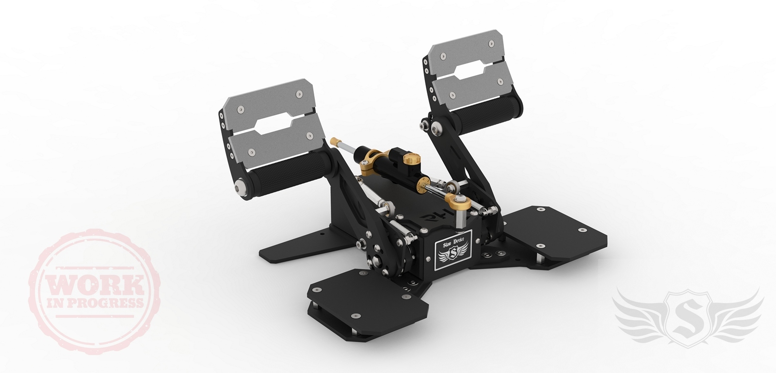
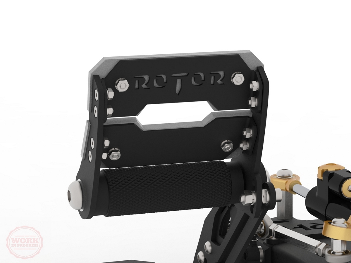
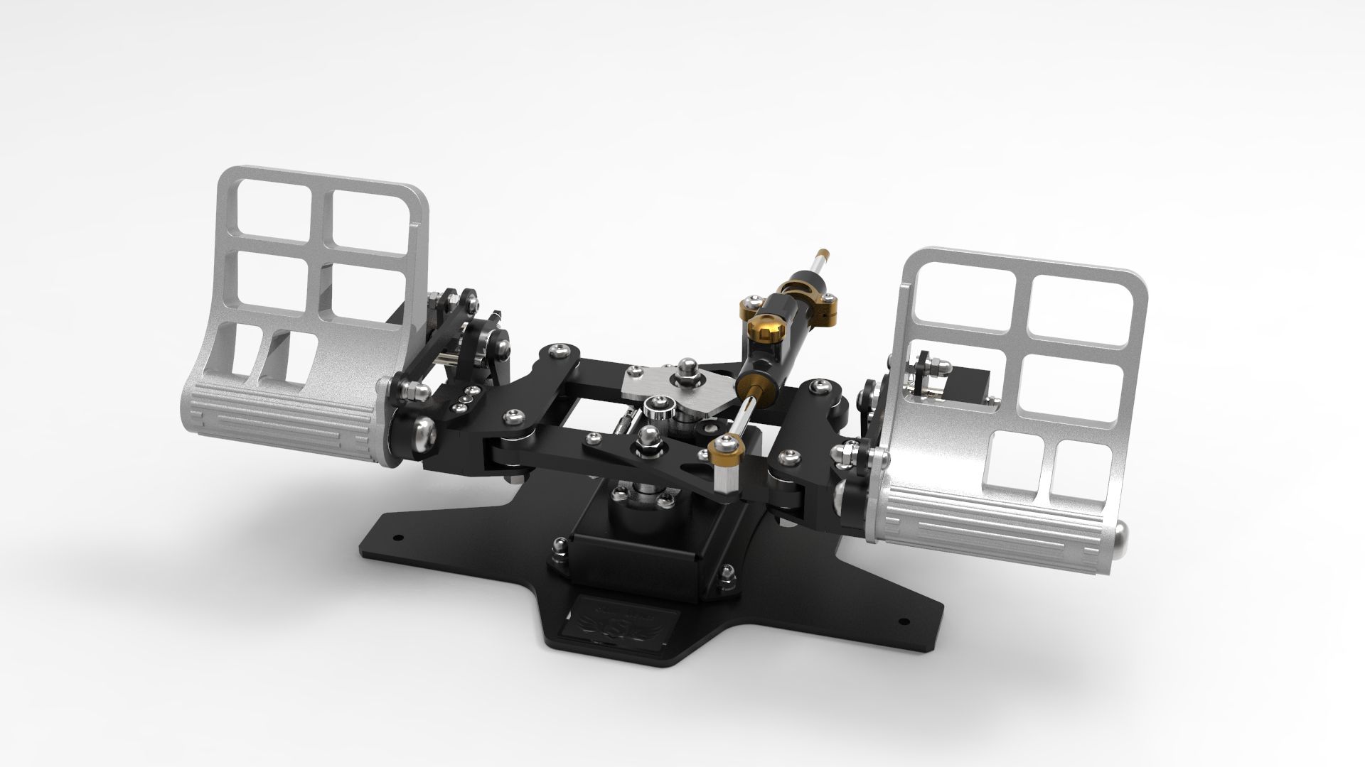
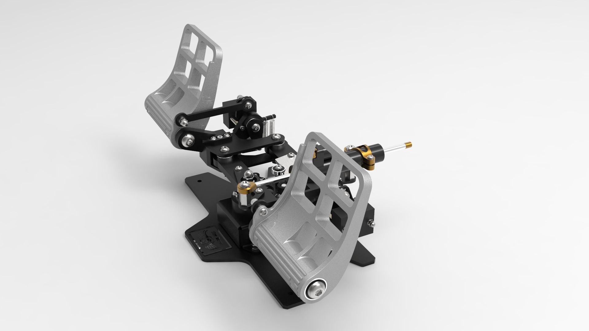
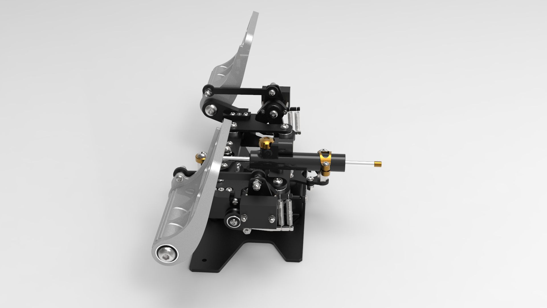
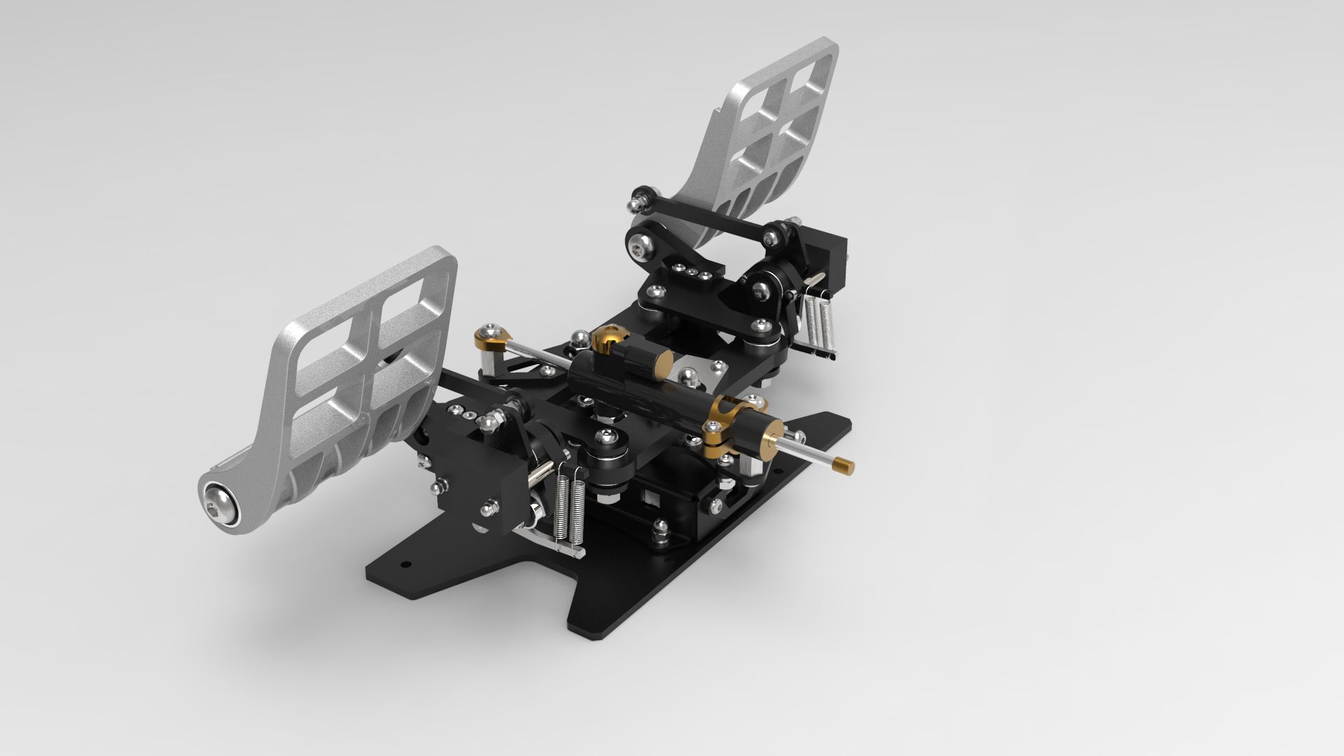
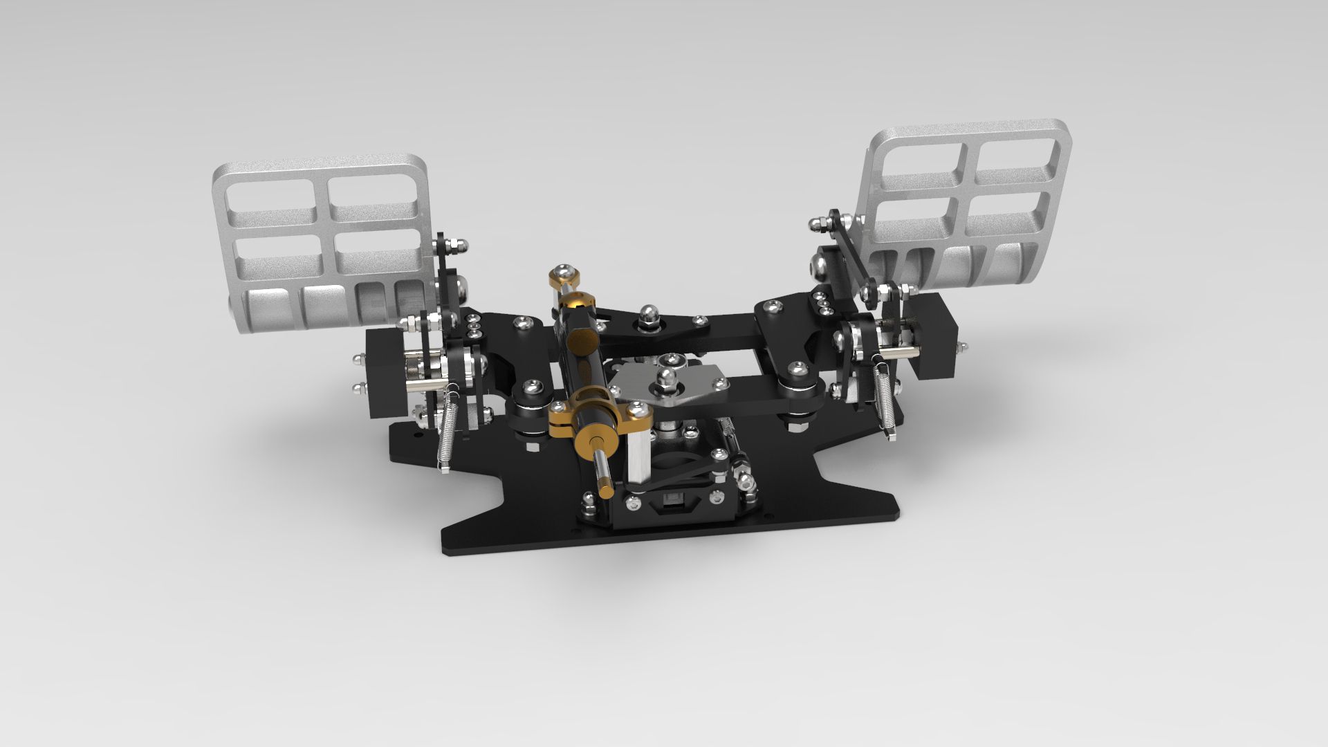
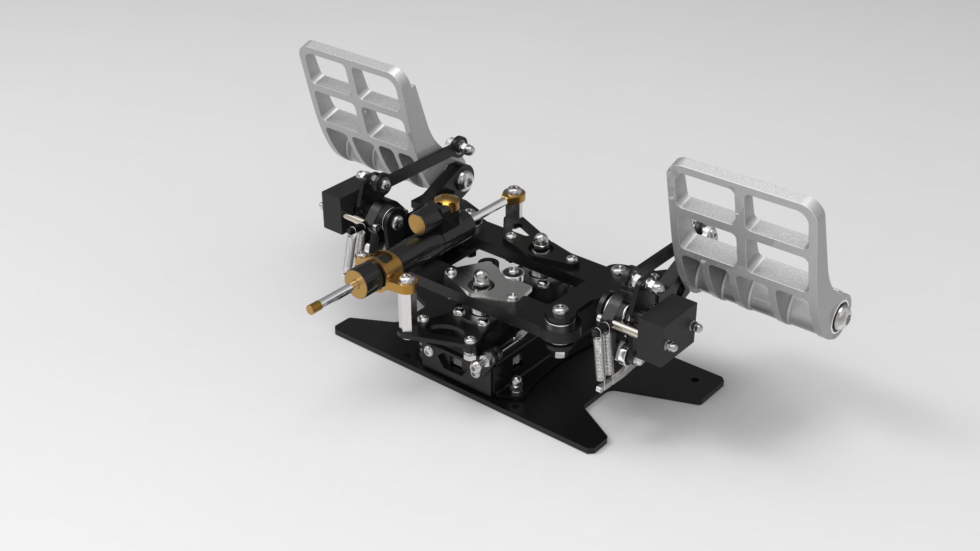
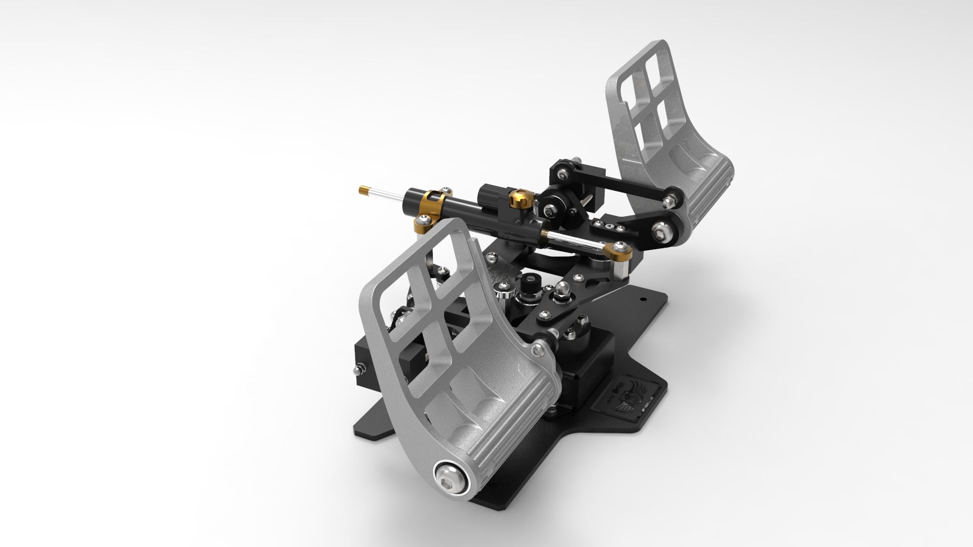
1. Pedal width - 435 mm. The pedals were projected so that it would be convenient to use the joystick installed between the legs. 2. It's hard for me to explain it in English, but I'll try. The mechanism (operation) of the brakes has no analogues. In all such constructions, the angle of inclination of the brake pedal relative to the floor does not change during rudder operation. That is, when the rudder is working, the brake pedal turns towards the pilot, maintaining the angle of inclination relative to the floor. This leads to unwanted pressing of the brake pedal. This is especially negative when the pedals are set to the minimum angle, as in the last photo. Therefore, the construction of the brake mechanism was made such that the angle of inclination of the brake pedal relative to the pedal lever is constant (does not change during rudder operation). The pilot can rest part of the foot on the pedal. This is more comfortable than keeping your foot on the cylindrical part of the pedal only. For braking, it will be enough to press the pedal with your toes (in any position of the rudder). -
Slaw Device RH "Rotor" rudder pedals
Slaw replied to Slaw's topic in PC Hardware and Related Software
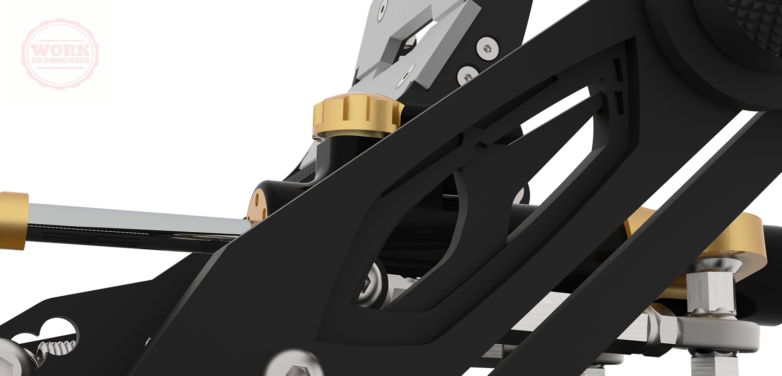
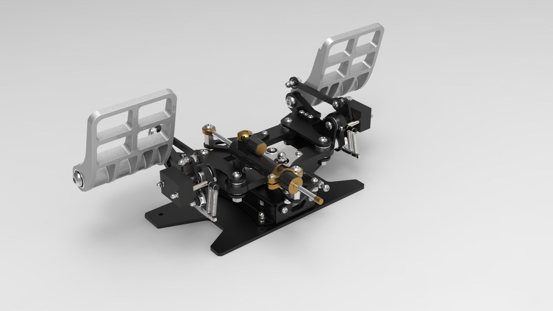
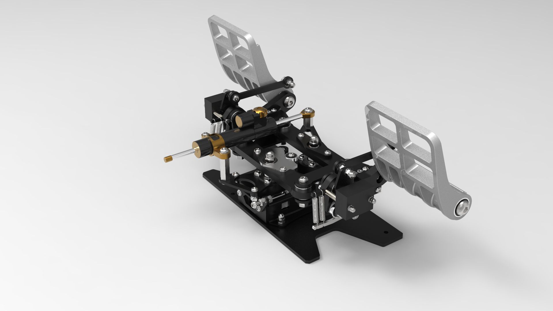
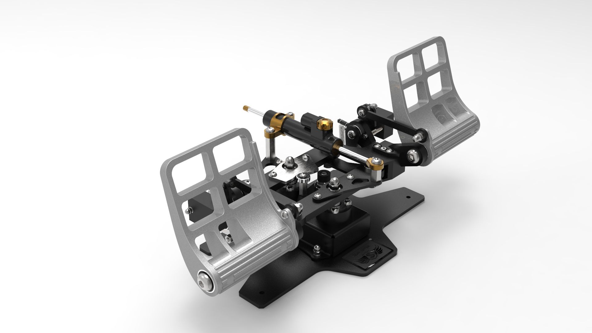
The cam is double, with the same profiles as in the Viper pedals. (free center and hard center) Main spring tension adjustment is present. At the moment, the possibility of rearranging the brake spring tensioner has been designed. There is only one spring. The position of the tensioner and the parameters of the spring will be determined during the tests. But you must understand that in this design, a large resistance of the brake pedal will negatively affect the operation of the pedals, it will be inconvenient. Therefore, at the time of design, it was not intended to create high resistance on the brake pedals. -
Slaw Device RH "Rotor" rudder pedals
Slaw replied to Slaw's topic in PC Hardware and Related Software
The pivot point of the pedals is located near the pilot's heel. The brake pivot is on the pedal axis. -
Slaw Device RH "Rotor" rudder pedals
Slaw replied to Slaw's topic in PC Hardware and Related Software
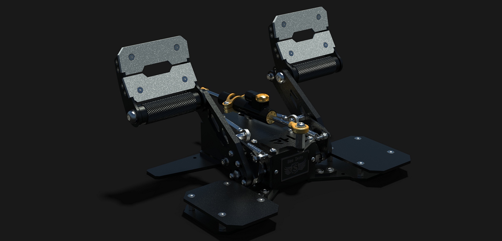
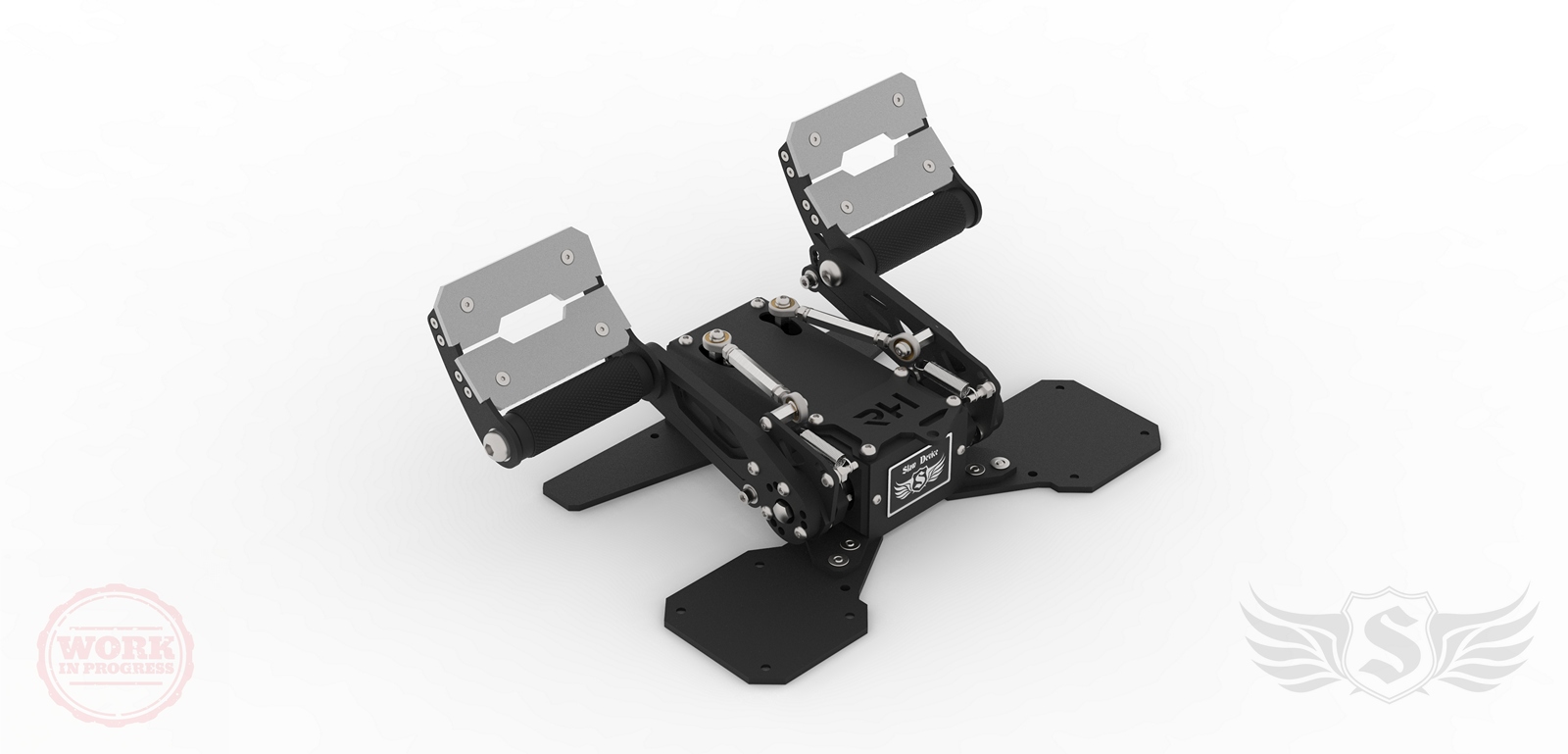
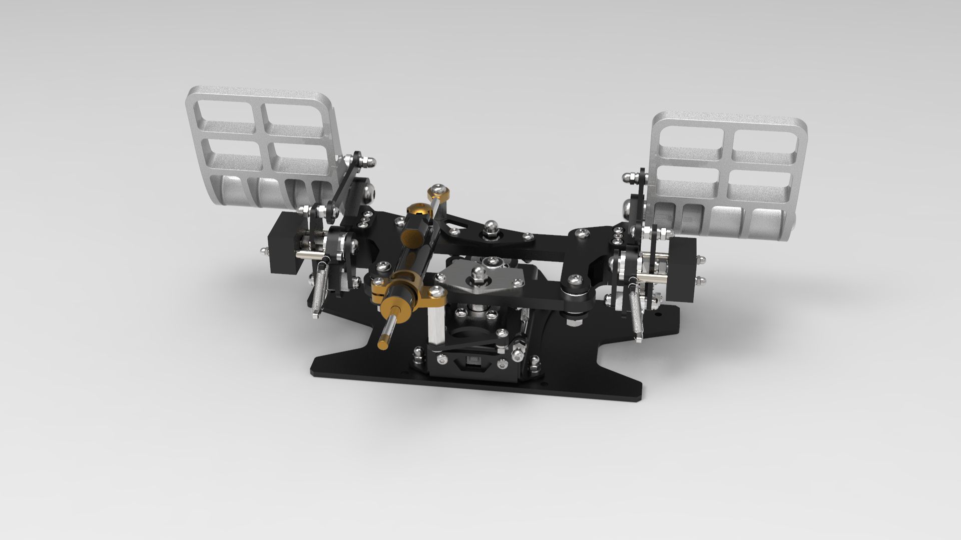
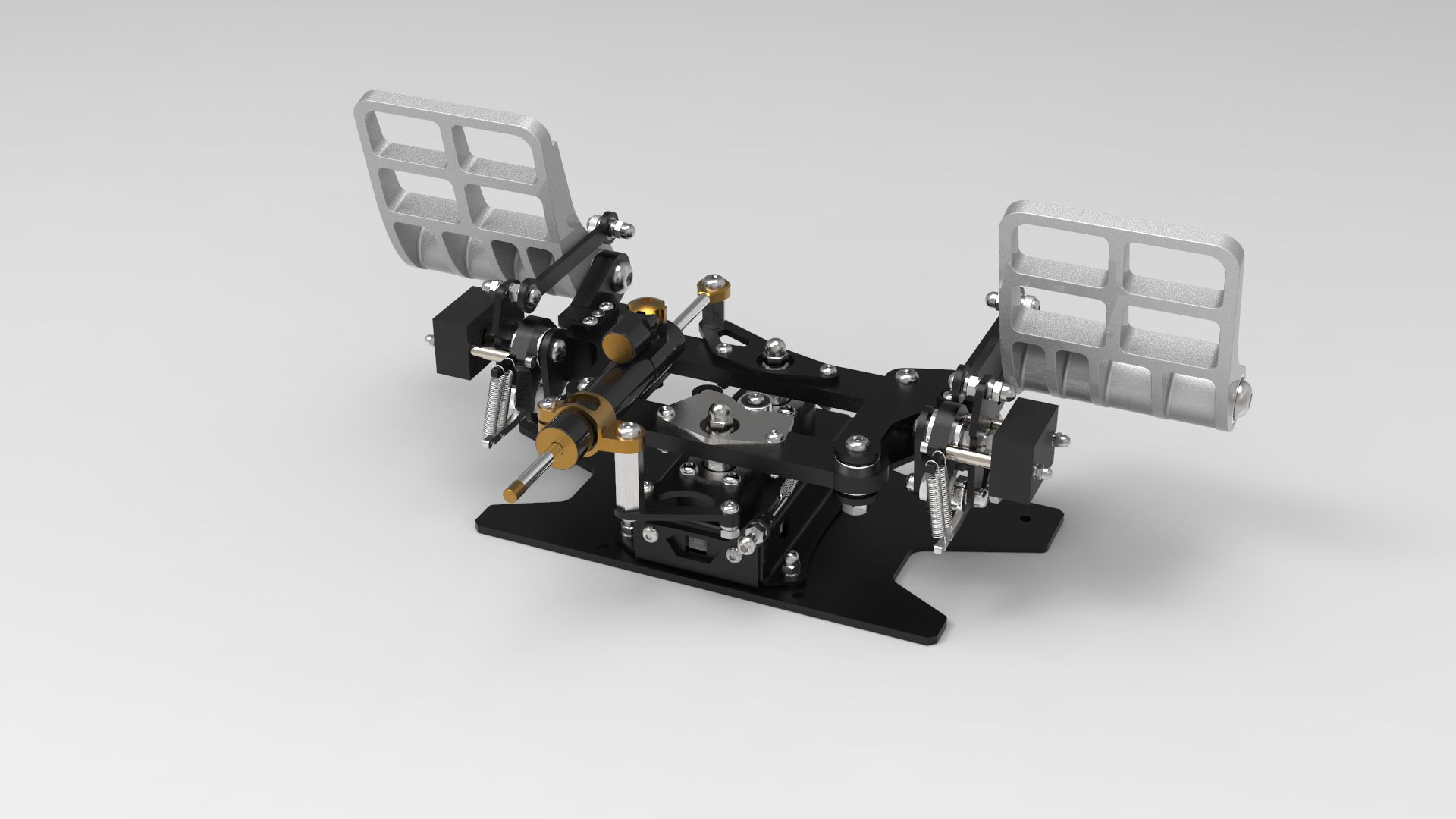
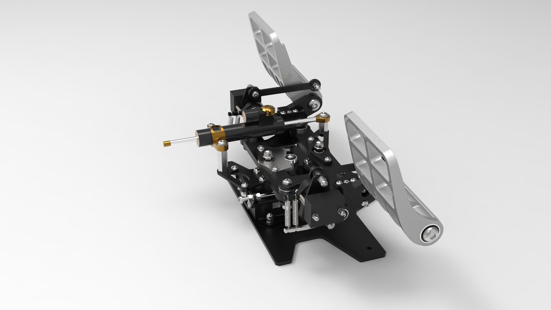
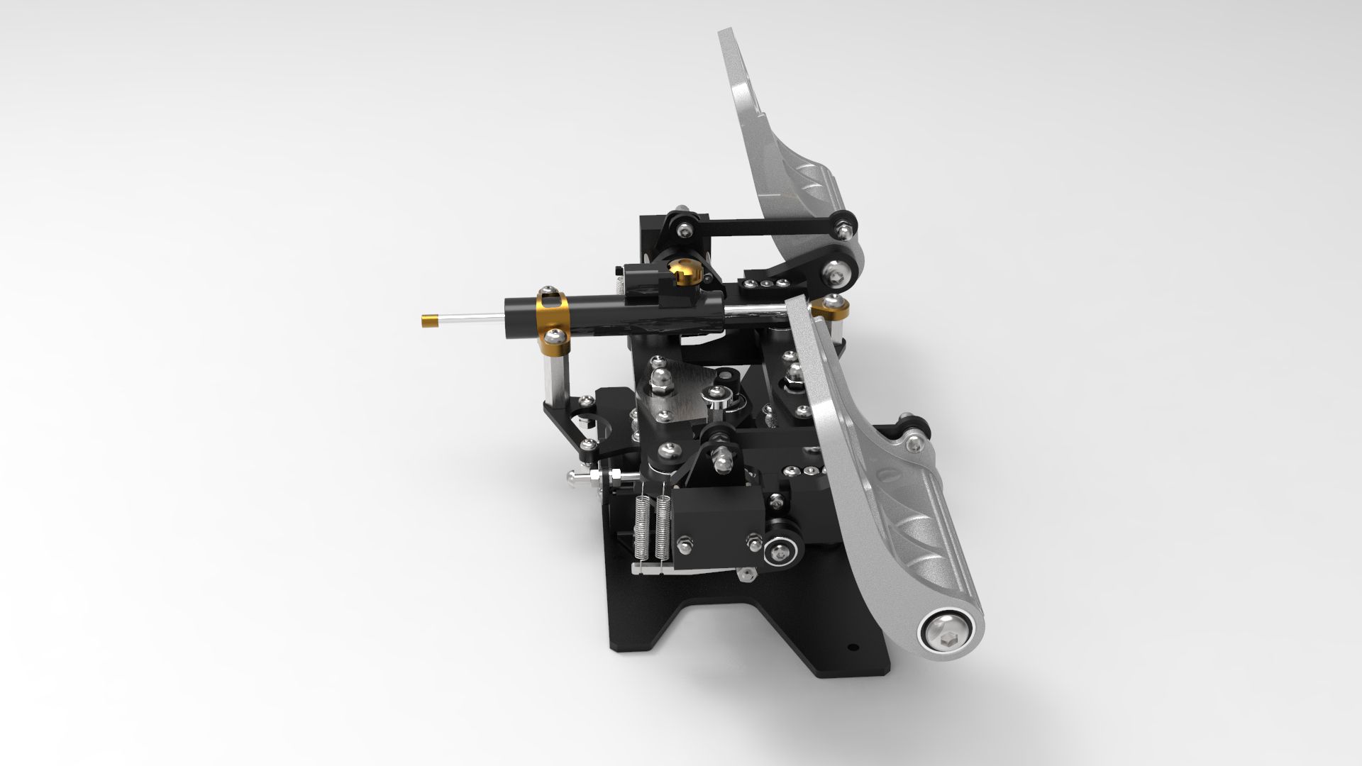
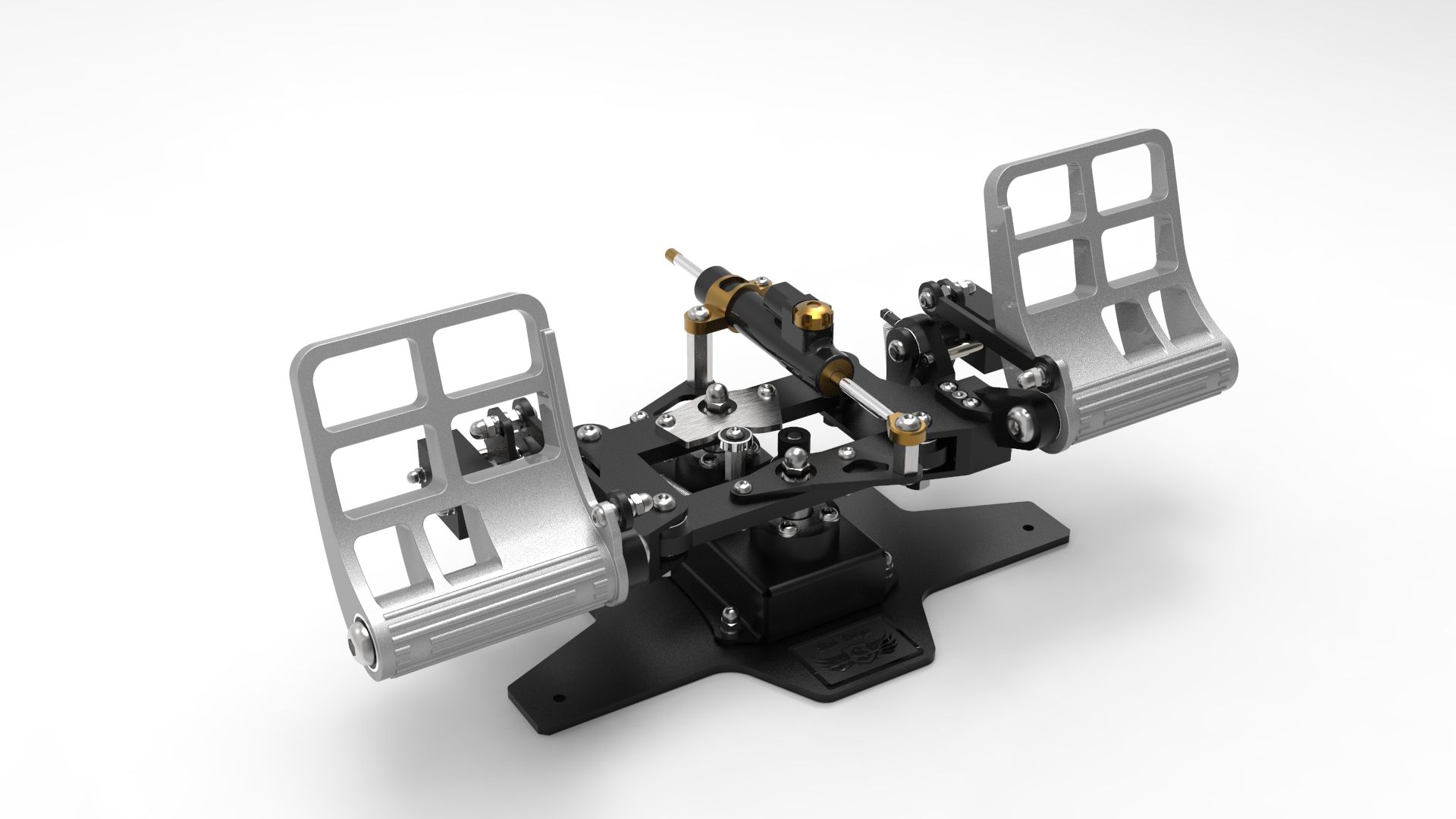
1. In everything. These are completely different devices. 2. Damper is only an option. Will not ship with pedals. Everything you need to install a damper will be included. 3. These are three-axis pedals. Brakes are present. 4. The pedal mechanism allows you to change the angle of the pedals. There are three fixed positions. The last photo represents the lowest position, all other photos represent the middle position. 5. Many real helicopters have a similar kinematic design. Apache, for example. But this does not apply to the brakes. In these pedals the braking mechanism is different. This is for the convenience of using the brakes at any angle of the pedals. -
Hi, All! This is our new project - RH "Rotor". In March - early April, several units will be made for tests. After that, more information about this project will be provided. If you have any questions, please ask. Here are some photos (render).

-
-
-
-
Как бы то ни было - материал - важная вещь. Которая, из за своих свойств решает многие проблемы механики. Второй вопрос - кинетическая схема, а в частности расположение опор и движущихся частей (проще говоря - механика подшипниковых узлов и плечей нагрузки). Со второй стороны материал и его обработка - большая финансовая разница в производстве. Покупатель должен знать, что он хочет иметь: двигающуюся машинку или движение на машине? Даже не беря во внимание материал, схема Романа лучше. А если учесть электронику, не ведясь на 4096 отсчётов озвученных в рекламе Миланом и понимая, что 2500 РЕАЛЬНЫХ отсчётов бесконтактного магнитного датчика, типа РАМС, МАРС или датчика от Virpil на много больше, точнее и стабильнее виртуальных отсчётов MFG Crosswind, то становится ясно, за что платим. Да и вообще, простой ХОЛЛ, используемый в MFG Crosswind - давно умерший старик на нашем рынке, который ещё существует из за реклам для тех, кому уже пофиг, либо не представляют ничего лучшего. В любом случае на цену влияют многие факторы, зависящие от материала, технологии, страны производства и её налогов, дополнительных материалов и реклама. Последняя рулит, как я вижу. Тогда зачем доказывать другим, что вера в рекламу является священной и единственно правильной? Известно, что темы в таком роде не дают конструктива, а приводят к срачу пользователей, которые не способны признать ошибочность своего выбора.
-
All depends on the model of pedals and the date of their production. Previously, we equipped the pedals with springs 50 mm (default) and 60 mm spare. Later and still (when we increased the length of the tension bolt from 40 to 50 mm), our pedals have a spring for the rudder axis 50 mm (1.5x10x50). Spare spring is the same.
-
Here I will share photos of our unrealized projects.........................yet......:smilewink: F16 Rudder Pedals.