
weeb
-
Posts
289 -
Joined
-
Last visited
Content Type
Profiles
Forums
Events
Posts posted by weeb
-
-
:lol::lol::lol:
Thanks Weeb. I understand now. Just hit me like a kick in the nuts...:megalol:
I must say the expressions one hears from having access to so many different countries and cultures, its sometimes just boogles the mind how we are ever able to understand each other without actually having spent time in each place to learn the language.
BTW Weeb, are you all heeled up and out of the hospital by now???
John
PM bro
-
Ya sure I knew exactly what you meant with your accurate description of what you wanted.
That why sever others all so asked what the heck are you talking about.
You have a problem get over it or deal with it but don't bother to directly ask me any thing else. I personal could not care less if you do or don't purchase any plans finish your cockpit or not. Your a moron.
You know something, I am not even going to get into a strop (what ever you americans call it) Funny how most people on this forum understood what I was asking. You know abso/****in/lutely nothing about me apart from an address you sent the gauge to and you call me a moron. Wind your kneck in m8 you are starting to show your colours.
-
I want to know what a bollock is. :P
John, in Scotland here, it means, your nut, testes, boz, plum, ie contents of the boz sack :thumbup:
I raised this question as a genuine article, but it seems to have kicked off, In all languages can you tell me what a ball (nut) means in your native language
:D
-
Thanks cookie, Anton,Callum and Ragtop, between the 4 of you, you have answered my question. I will have to expand my rails or shrink my lcd. Bottom line is I thought the 20 x2, would fit and would solve the 4 space extra space issue but I guess i will have to go 16 x 2. It's a problem, but not insurmountable. To Deadman get your head out your arse, 4 understood, you didn't allegedly. I have 3 x 20x2 lcd's if anyone needs and can use, cost me $17 a pop
-
 1
1
-
-
Thanks Cookie, spot on, typo there. Cheers bud.
Ratcatcher, I have this horrible feeling that I am going to have to redo the side consoles. That CMSP panel did make my bollock drop as I realised the only way to fit it into the space between the risers was using "Schwarzschild's field" or Event Horizon whereby if I spin it faster than the speed of light it becomes smaller. Gotta try that lol. :thumbup:
-
By the way I'm not AWOL, hiding or just invisible, been busy will post as I progress unless anyone in particular want's to see what i have been up to. Been laser mode for a while. :megalol:
-
I built a lot of the infrastructure using Dimebugs plans which are awesome, once or twice I've come up against problems that don't work out mathematically, sorry, i'm anal about accuracy. Firstly I am not going to put Dimebug down as I would never have started without him. I have a question tho, maybe DM can chime in without quoting his sig, just tell me what is the width of the console incline and decline. IMHO I think they are too narrow. Don't say buy my plans, I started building this months ago and your plans weren't even in the offing then and are still in the ether. If I have to buy the plans then I will, but I was looking at how far out I am and do I need to start from scratch or can I do a damage limitation here.

-
Beautiful job on the matrix there m8. Just a quickie. To save ripping apart chargers etc to get a voltage stepdown, I use these when I need to vary circuit voltages. They are very small in physical size, cheap as chips but very effective. You can set the Voltage/brightness of LEDS, takes a bit of trial and error though. Bought a few of them and even got a discount.
Can you see any problems with them?
http://www.ebay.co.uk/itm/161419156290?_trksid=p2057872.m2749.l2649&ssPageName=STRK%3AMEBIDX%3AIT
weeb
-
Cheers Anton, I will give you a shout later. I get out of hospital tomorrow. Not happy using hospital unsecured wireless network and I don't have my burn dongles with me unfortunately.
-
PM sent Tom
Cheers weeb
-
Nothing too serious John, smashed my leg to bits several weeks back and it has an external fixing with 3 pins directly into the shin bone. Got kinda infected so back in to get mended. Means i'm lying around doing nothing constructive, so I have a chance to read and study up. More frustrating than painful m8.
-
Cheers John, appreciated m8, gives me something to study in hospital. :)
-
OR you can try this.
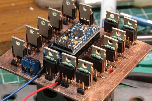
I needed to light all of the indicators from one Pro Mini and many LEDS were of a much higher power than the board could handle so I elected to do this:
You must realize that most of this (electronics) is new to me and I am on a learning binge. My solution was to use logic level MOFSETs (30N06L) to act as a switch for every LED indicator that the A10C has including AOA indexer, AAR Status indicator, Guns, Nose Wheel, Beacon, Canopy, Fire and the list goes on. One pin per indicator on the Arduino board, 12v in for the indicators, header pins to attach each indicator and everything labelled on the board in case I forget. What do I mean "in case I forget" ... when I forget. Its an easy circuit and if any one wants a copy I can put a PDF up.
John m8, I would be interested in a copy of the pdf if possible. Kinda fits round my way of thinking. Could you oblige. Many thanks
weeb
-
I'll take one DM, not at home at the moment, but can be contacted.
Weeb
-
Thanks Anton for your continued input.
I have followed your thread constantly but unfortunately I think your solution is brilliant but I can't put that into my flat here. Building restrictions etc. SO I am trying to work with the best I can. Hear me out for a second:
I intend to get rid of the duck-billed platypus vent and leave just the pillar-box hole. I will tig weld up the cutting compartment leaving it airtight, including the stupid hole in the side where it vents to the motherboard. I have no idea why its even there as the power-supply has a fan.
So I I force feed air into the compartment, it has only one way to go out. Like a supercharger venturi effect. I don't know how efficient it will be until I try it. I am looking at a cost effective way to use a chinese laser in an enclosed area without killing myself or my neighbors. I will keep you updated m8. :thumbup:
-
Thanks Calum, that gives me another pointer. Appreciated m8. :thumbup:
-
One concern I feel is my CH Rudder pedals. First when placed on the plate at the front I get the impression that they would be to far back judging from pictures. Also can it be placed on that plate and not glide ? Or will it need to fastened ?
You can mount them without the plate and put them anywhere on the X axis. Far away or close to you, it's all adjustable. Think I have used it in 3 different positions so far, It just slides up and down on the tubes m8.
-
I've been looking for a touch screen to use as a CDU for the A10C. The problem is the smaller touch screens all appear to be connected using a USB and I've heard they aren't that good. I also want this to work with the program Ultra MFCD and I'm not sure it the Usb ones work with this program.
Does anyone know where I can get small touch screens from? Preferably, ones that don't use usb if usb ones are rubbish.
Who said they were rubbish Joe? Problematic yes, rubbish no! I've never used UltraMFCD so I can't comment on that. They have their issues but they are automatically identified by windows 7 and above as part of the pen and input so that has to be a benefit, why do you need a touchscreen for the cdu? Its all done with buttons?
-
Right here we go:
I live in a bought flat without a garage so I have no option but to make this work and not poison me or the neighbours. The supplied 120 mm fan is nothing short of a joke. Cut away, it's looks like this. Totally inefficient 2.5m3 per minute. Pulling through a pillar box hole 17.78cm x 5.08cm.
Whilst waiting for my X7 conversion kit coming from the States, I got a hydroponics fan, same wattage, but 150mm fan shifts 300m3 per hour instead of 150m3.
A simple ducting convertor:
When I was diving in my career, our masks used positive pressure to keep water out at depth so It got me thinking, stick another of the fans on the front pushing and the rear one pulling, when I have sealed up the cutting chamber, it only has one way to go, so atm, cutting plastic fan duct to make it fit exactly over the pillar box. I think it should work, but will only know when I fire it up. Am I mad or is this normal behaviour in the flight sim cockpit building community. :)
-
Ian;2368277']You need a separate resistor for each LED.
The single resistor in your schematic sets the current for all LEDs combined, but you want that current to be different depending on the amount of LEDs that are on at the same time. It also won't be distributed evenly between LEDs due to manufacturing tolerances.
Assuming a forward voltage of 2.4 V, with a 1 ohm resistor you should get a current of 2.6 ampere (2600 mA). Either something is already broken, or your circuit does not match your schematic.
To get the 13 mA you are measuring with a single LED, you'd need a 200 ohm resistor (again assuming a forward voltage of 2.4 V).
Thanks Ian and Tore, I was going to ask someone to share a wiring diagram because I am so way out of my depth here. My occupation path during my life did not involve designing electronic circuits so I am learning as I blow things up. :music_whistling: You know something, I thought the caution panel would be the easiest one to build, and boy, did I find out the hard way, I'm still flummoxed with the whole thing, nearly made me give up with the whole pit build, but I gave myself a slap, all the money I have spent so far ain't going to waste. I think it is really difficult when, say!, you were good at your profession, and you come into this and hit walls, and it's way out of your comfort zone. Sorry Tore didn't mean to hijack thread just felt it was important to let people not to give up when the chips are down.
-
I came across this problem when I was throwing together a caution light panel and I failed miserably, but, I got up, dusted off and went straight back into it. I tried a single circuit, with a resistor at the back of each LED, it worked fine until I pressed the caution light test switch, that put them on all at once, and hey presto, a melt down, rethinking this with with an open mind, I thought it would be simple but it shat on me, physics was never my strong point at school. I was using 12 volt by the way tore :music_whistling:
-
So how is the story with the seller progresses Weeb?
"Milling" recesses for mounting nuts in 6mm acryl sheet with laser , it actually worked quite well. While finish is poor it is not critical in this particular instance (the smooth white behind is a sheet of lasermark)
That looks really good for a first attempt bro, well done.
My saga continues: Replacement arrived out of the blue yesterday, everything physical appeared ok with the exception of the on/off laser switch being broken. Easy sorted, ordered 6 from China, I can use the other 5 nps. USB stick was there as was a software cd containing:
1. The latest CDR software Windows 7
2.The latest Chinese easy engraving software Windows XP
3. Coreldraw 12 - English.rar
4. K40 installation instructions
There is No video for setting it up.
Unfortunately there is a circular scratch round the written area of the cd making it unusable.
I Emailed them back and they sent me a link to some software but there are no instructions anywhere how to install it and no link for CorelDraw 12.
Do you have the same laser by any chance? If so could you email me any software setup instructions. I'm just frustrated, I ordered and paid for this on the 23rd of February and I'm still not up and running yet.
I suspect I will have to go toe-to-toe with them to get my £15.00 discount for my troubles and my postage cost of £50.00+. I'll keep you guys in the loop.
-
That sure looks like the same thing Weeb. It even includes the capacitors and the resistor you need. But please be aware that the resistor value may not be correct. You need to get the data sheet for the MAX 7219 and read the section on calculating the resistor value based on your particular application. Its under in the section that describes the "iset" pin on the 7219.
Cheers John, I will do. I'm almost anal about RTFM. I saw it as an all in one solution for absolutely minimum cost outlay, hence I got 4 because I'm sure to annihilate a couple whilst I'm buggering about with them. :music_whistling:
-
I just had a look at that web site again and I see they asking 26 Euro's with 10 Euros shipping. Thats like $40.00US And did I say stupidly priced. I think its down right robbery.
Now if you can solder, then assemble your own based on the following. Its really not very hard as I did it and last year I knew nothing about this stuff. I couldn't even solder worth a damn. I actually made my own PCB and went from there. But you can buy one from China and solder it up yourself save a shitload of money.
Here's the cost breakdown:
MAX 7219 from China - 2 for $1.50 = $0.75 ea.
PCB already made for you - $1.68
Connectors: $0.50
Couple of capacitors, a resistor and a bit of wire. $1.00
Complete cost in parts $3.93 and no shipping charges vs $40.00 from a commercial outlet.
Hello??? thats 10x the cost of making it yourself. Whats wrong with this picture people.
Make your own everyone. Its not that hard.
Just ordered 4 of these to play about with. Is this what you are talking about John.?
http://www.ebay.co.uk/itm/371185933064?_trksid=p2059210.m2749.l2649&ssPageName=STRK%3AMEBIDX%3AIT


Have I dropped a bollock here.
in Home Cockpits
Posted
Autocad 2014 m8
Don't like the way the cloud has become, photoshop did it for me hence I still use CS6 that doesn't require an internet connection, autocad went the same way with their 360 shit. I want to be able to work on things without an internet connection. Maybe I'm a dinosaur but it works for me. :smartass: