Schredder
-
Posts
43 -
Joined
-
Last visited
-
Days Won
1
Content Type
Profiles
Forums
Events
Everything posted by Schredder
-
Hi. After I got sick with commercial home routers,I've been looking for something different. I love gaming as we all do... Ping issues are a real pain and overall ability to control and maximize my connection are in high demand. I plunged into pfsense about a month ago. Building my rig from spare old parts. Used i3 with 4 gigs and sata ssd which were laying around. Added picopower adapter and 12V power supply and saw the magic happen... Pings and packet loss are minimized and I take advantage of my ISP package at its full. Enjoying my rig - it died. Probably because of the power supply arrangement and the old,phisically bad shape hardware I used. Decided to buy new, dedicated hardware. I used J4005N D2P from Gigabyte. It has an integrated ,dual core celeron cpu. This is ,for my opinion is a good sweet spot in terms of price,power consumption and performance. The static cooling seals the deal. Added M2 SSD. also from gigabyte but anything would fit here. It's an overkill, I know, I just like the small footprint.and its relatively cheap. A full size ATX power supply is used. Picked a semi modular gold rated PSU for efficiency and low temps. Added pcie gigabit NIC. Added LCD for data and fun. Utilizing LCDProc. Fixed everything on a plate and covered with engraved plate I made in my homemade CNC. Im delighted with the results. If you suffer from network lags/ issued and even if you dont. You might want to read and see some info about these open source router disto. Attached picturs. Regards Nir https://drive.google.com/open?id=1jPlSlCeUy9psnHYCIVn4s-fnripltjcc https://drive.google.com/open?id=1-8G7_ujsgiy51LqwQCuVcCLIfXuo4dYf https://drive.google.com/open?id=1-24Kp4dT7Je-t4t5LgQC1aFlEobwU4Ce https://drive.google.com/open?id=1-5EGt6o2ecCukC2bBtvs41W4aNSTsDW8
-

Button Box Enclosures?
Schredder replied to iKyrThraad993i's topic in PC Hardware and Related Software
What about 19 inch rack enclosure ?! a great base to start with... -
Generic input control panel
Schredder replied to Schredder's topic in PC Hardware and Related Software
This board identifies and acts as a joystick. not a keyboard. I have made some other work for controllers with lots of input headers so everyone who's not very familiar with electronics could use without spending so much money over it. I intend to make it open source. once I have the final design. Cheers -
Generic input control panel
Schredder replied to Schredder's topic in PC Hardware and Related Software
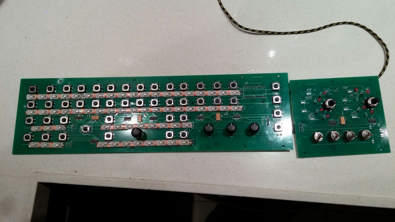
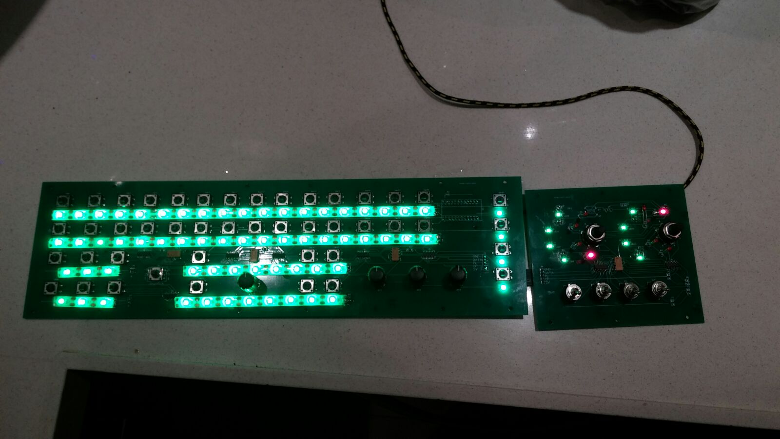
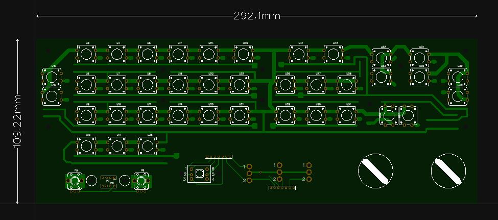
Some progress... The main board has 44 pushbuttons,1 HAT switch and 4 axes with center detent. Optinal addon panel adds two 4 position rotaries and 4 double action toggles. Next comes the enclosure... Cheers
-
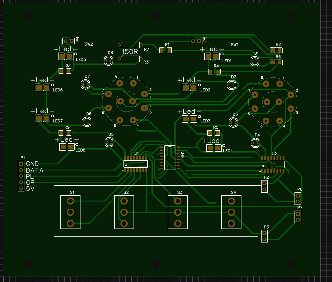
Hi all, I was asked from some friends to make a generic input front panel with buttons ,toggle etc... Made one. parts are on their way... I'm pretty sure I'll have some tweaks to make but afterwards I think to make some and sell. maybe as a kit to assembly or a full ,ready to run product. This panel can be expanded with daughter boards (one is already designed and on its way too). My intention is to give a good , affordable and easy way to novice users who are willing to expand their input options but simply don't know where to start. Major guidelines and requests were(please add if you can think of more): Big PCB's to solder everything minimizes wiring mistakes. A step to Step guide to write the Firmware. Surface mount parts will be pre-soldered upon request. Will have its own casing and parts to assemble a full panel. Will be "seen" as a regular input interface - thus no external software is required (but can be used). Mainboard will have: 1 hat switch 4 way. 4 potentiometers (axis input) with center detent. 42 pushbuttons First Daughter board will have: (this board is optional to further expand functionality) 2 rotary switches 4 selectable stations each. 4 toggle switches. double action. Both boards will have backlight "windows" - this allows to print on a transparent sheet (will supply template) with dedicated configuration to each of your modules. this can be changed in an instant.Lift one ,place other. Attached pictures(not to scale). Will update on progress. Cheers !
-
Thank you all, I understand what you mean. I'm doing it of good will so everyone could start a pit or at least a panel for his rig. Will try to keep it simple - that's the main idea. yet it has to be flexible enough so it could evolve with time. Mr_Burns I would gladly hear what you need and want from your perspective. The Main intention is to make like a "LEGO". have the build blocks. then connect them together. I call to anyone who want to take part in ideas /capabilities what is required and what is the best way to achieve them. There are a lot of modules out there for Arduino's and other controller boards. Yet, these are very general. We need to design OUR OWN arduino sheild and standardize it. The next connected boards will allow the input of AXES,BUTTON,ROTARIES,TOGGLES,ENCODERS... Lot of us share our knowledge. But if someone has difficulties with software/hardware side - he will probably won't get into it... I'm not familiar too much with software dev. side, but I'm sure there are qualified persons here that can make a configurator. actually , there is. MMJOY is great ! It would be easy to take a set of standard boards. connect them together as described. load the config profile and there you go... No Coding. no soldering... just the pure fun of using a drill,saw and screwdriver... :) It will be easy ! like these two pins are a button. these also... so on... Good engineering , with good documentation and strong community will make it work. Guys ! step in. make a difference to those who really want but cant or simply afraid to start... Post me. We have a lot to discuss about Mr_Burns. PM me with you're detail so we could talk online... Cheers to all !!!
-
Hi The answer should be coming from all of us. I'm trying to establish some sort of bank. with build blocks. A unified main board (breakout board) which hooks to an arduino. Community developed end boards will be constantly designed and populated. To enable that - the main board has to be standard(and it's up to us to make it right on the first time). Each DCS module has its own requirements.its common for one to make a generic pit to fit all the modules he has(we can still make our own high fidelity pit using it). I think it would be nice to have a "modular" design, so we could get the blocks together and hook it up the way we want it to suit our needs. make our own profile and to be left with building the hardware - each as his wish. With the cheap arduino boards and the versatile options we can get, designing something which is tailored to our needs it could really make an impact. Cheers :smilewink:
-
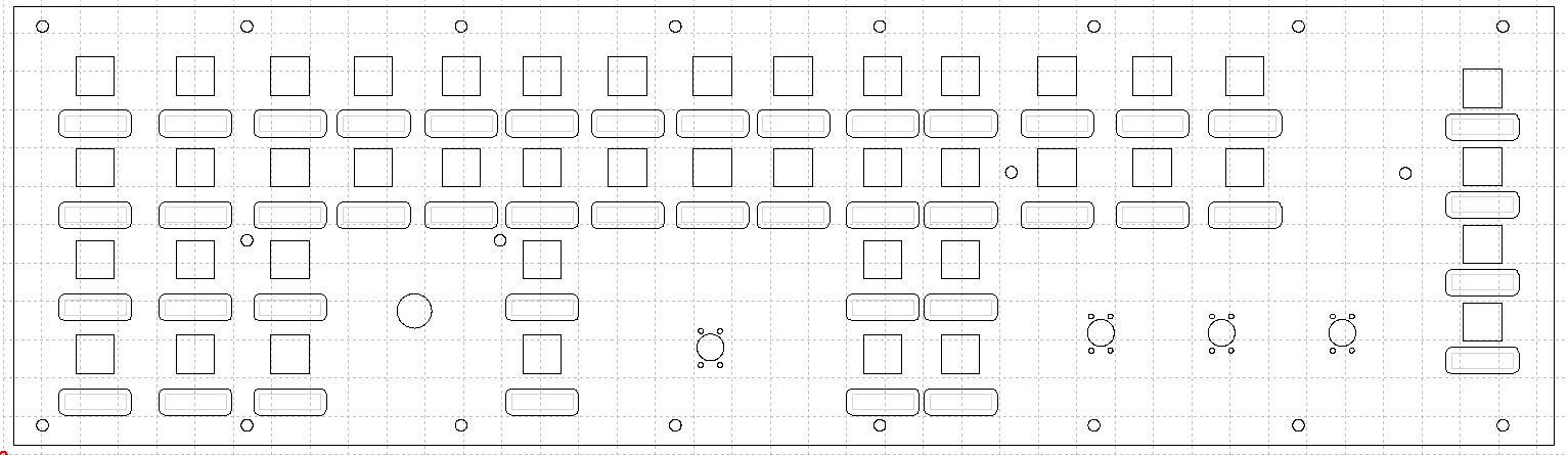
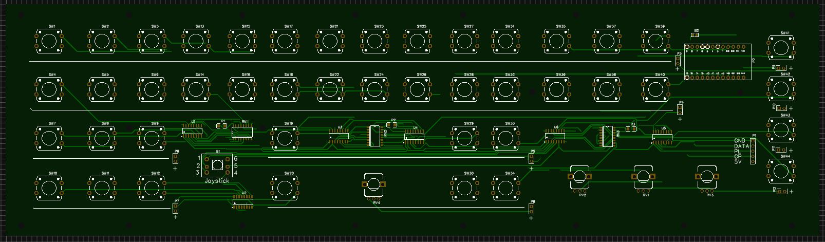
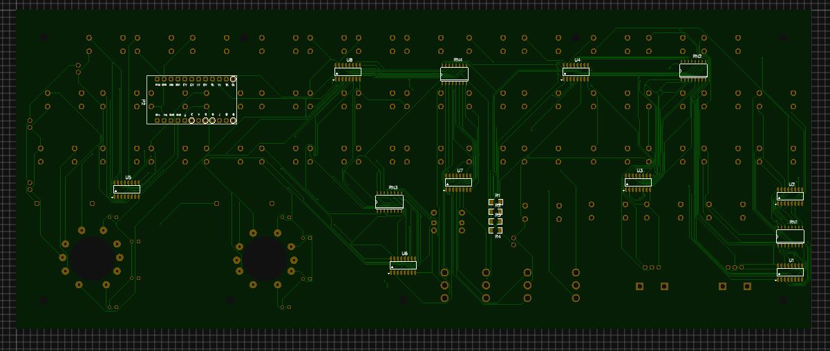
Mmmm... Kinda disappointed due to lack of interest...:( I might be mistaken and everyone can build the electronic controller part...:tomato: Anyway some progress.. Final locations and routing. maybe some few more adjustments... Later will work on the casing. Should I start with a controller with connectors ... Help me out here...
-
Hi All Sorry for the blown up headline of this thread. It's been a while that I'm considering to develop a general custom made board for inputs. One that will be for general purpose , rather than module specific. My guess is that there are a lot of simmers who are not familiar with the electronics side. This is a HUGE barricade to overcome when one decides if /how to build a cockpit. I want this crowd to have a better starting point to start with. Using off the shelf components and controllers sets along with a kit of parts they can all get into the loop. I'm half way to deliver a general purpose input panel. It could have variations later on. I think I will also make a general purpose break out board with good informative yet practical "Cockpit for Dummies" documentation. For budget reasons I only going to make 10 boards for the first run. THIS INITIATIVE IS IN NO WAY TO MAKE ANY PROFIT ( I have my own job for it). After several major designs are established - We can turn them into some sort of a STANDARD. Meaning - we could support each other. I'm only the initiator of this idea and I will gladly share production files to anyone once we establish final designs. I have a humble vision to make a path for a community effort. Where those who can will harness their skills and knowledge to make things for others who need it. There are , indeed A LOT of great community oriented projects. these are great ! Yet , a lot of it is very overwhelming to the novice users who are clueless about electronics... The main intention is to deliver one or two variations of general purpose input panels and one general purpose breakout board with several end boards / terminals. Each will come as a kit. the panels will also have their enclosures. Now for those who want to assemble their own - will purchase as a assembly kit. For those who wants a PLUG AND PLAY solution could buy is from users who will make it for them for some fee. Either way. custom design. community oriented. for the community.in reasonable price and quality. I would love to have some more guys (and gals) to help with this initiative in terms of thoughts ideas. It starts like this (attached). Will keep updating. Cheers !
-
Open Source Joystick FFB / DIY FFB Joystick
Schredder replied to Berniyh's topic in PC Hardware and Related Software
Hi I'm watching this thread closely with great interest... As from my experience there are some important things: 1) Which voltage level are you using to drive the motors ?! if the voltage is too low - the motor will develop poor torque. There is a complex theory about it. yet to put things simple - in order to get higher torque - one's need to raise the supply voltage. (this will allow the current levels to raise faster for a given frequency of PWM). Supply voltage not only has to meet , but exceed the rated voltage of the motor depending on PWM frequency , response time required , torque required and the declared Wattage ratings of the motors for continues operation. Thus been said , the way to achieve all is to raise the voltage. the problem it creates - is higher currents - not good for motors and for the entire project... Overcoming it is rather simple - using current limitation circuitry. What is the PWM frequency ?! A Transformer - is much more efficient at higher frequency. In DC motors - finding the sweet spot that trades off between torque to efficiency (for reduced loss of energy through unwanted heating) is a challange. yet can be resolved through trial and error... I just cant wait to see further progress on this breakthrough project ! Maybe I could help with gimbal design and drive circuitry... I think this thread is magnificent and I urge you to open a parallel post with already achieved milestones of it (files , REV's and more) . in this thread - will keep on active development posts... Cheers ! -
I believe that if there's enough memory on the arduino to hold several configurations - its tottaly possible. Upon initialization of the device - one of the pushbuttons of selected profiles need to be held down. Case statement(s) in the early stages of the program will then determine to which configuration to go within the entire code and loop it on the specific determined module. After the module has been selected - these buttons should now be usable for the module itself and not be wasted, since they were redifined in the module specific part of the program. An arduino reset button will allow to choose a different module in a breeze (Hold reset. press and hold selected module while releasing the reset). It's up to you "arduino wizard guys" to make the coding. and I'm conviced it's possible. What do you think ?!
-
Hall-Sensor mod for CH-Fightertick?
Schredder replied to Speedfreak's topic in PC Hardware and Related Software
CH uses fiber additives in their plastics , that's why they are rock solid. Their gimbal is not very precise because of huge tolerances between parts. The only thing I would use with CH is its grips. These are great to fit any frankenstein you'll dream on and will practically last forever... I did some work some years ago to make a mod that could fit any stick to become force sensing stick (as it is in the real F-16). If there's an interest - i'll put it back to the sketch board... -
Why So Few FFB Sticks?
Schredder replied to martinistripes's topic in PC Hardware and Related Software
Hi, Take a look at this: https://forums.eagle.ru/showthread.php?t=146343 I'm afraid that currently its the only option out there... Maybe we need to make some adapters to various grips. Incorporating the FF2 base, so it will be available for those who cant do it from their own reasons... Cheers ! -
Hi Guys, Iv'e been passive for a long time from these forums (life makes their own plans...) I designed and built some boards for making my local community a way to make their own panels. If there's an interest I will make some for you ( to fund my further developments) :smartass: This board enables 96 inputs. compact and simple. Using SMD components its very dense and could fit well in place without much "spaghetti" wiring. changing and trouble shooting will be simple as possible. I also made and will make some more breakout boards to enable flexability to various panels and controllers designs. In other words... My intention is to make some BUILD BLOCKS. so everyone could stack them together as he wishes to form his own panel. For example, This design came up in my local community as a generic panel to fit all with a good price to value ratio. Build quality is going to be preety good (I'm gonna run it with my homemade cnc) but everything in its time... Please share your thoughts about it. any comments and/or suggestions are welcomed. Cheers ! Nir
-
Hi again and sorry for the bump. I didnt find the X55 grip ergonomic . for me anyway. thought it will be ok but its not... anyway... Back to the old school ! :smartass: and final results are... Twist action is lost. but maybe it will make me finally use my dedicated rudders ...:music_whistling: Till next time... Cheers !
-
Using my lathe Iv'e made an adapter from the original X55 connection to the FF2 and fixed it using Epoxy. (if there will be more grips that will support this connection - it would fit)
-
Hi all ! Its been a loooong time since I posted anything. Life makes their own plans while you make yours... :doh: Anyway... Iv'e Been on some forums and noticed a repeatedly asked request. The majority of us knows the benefits of MSFF2 stick. have one ?! your'e one lucky BAS---D ! :lol: Problem is - one and only:not enough buttons. Therefore I decided on modding my beloved one, risking it and destroing not less than a Rhino X55 stick. (using the throttle only anyway along my FF2) Its a bummer that I didnt took much pictures. my workshop is a total mess. but thats the most of it... Well... this is the gimbal assembly. you probably reconginize it from earalier posts... The x-55 grip original PCB. Iv'e made another one from scratch and redesigned it to work with arduino. Another look The original and the replacement. currently just bulk board. still need to be etched. This is the final new "product". works well. I managed to reproduce the Led and detector arrengement for the motors enable\disable functionality. I still need to implement a stornger torque for the motors. Thus - redesigning the H-Bridges and the power supply. but everything has its time ... Cheers !
-
How can we improve multiplayer? Ideas.
Schredder replied to winchesterdelta1's topic in DCS Wishlist
I wrote my idea here. http://forums.eagle.ru/showthread.php?t=121515 Didn't had much response... -
Help choosing upgrade Graphic card
Schredder replied to Schredder's topic in PC Hardware and Related Software
My queries reveal that there are not much models of Nvidia cards that has 4 GB. most of them consists of "only" 3. Must I sell my soul for the "Titan"...:dunno: Is it "ok" to conclude that Nvidia compensates the less Memory oppose to AMD's parallel products ?! (more efficient use of memory , faster , etc...) AMD's Solution's has a better "dry" specifications over Nvidia's... Memory , Band , Price of paralleled products.. (more ?!) Yet , AMD's Drivers seems to be problematic... Please shed some light. I'm really confused... -
Hi All I currently have an Intel i7 3770K with 16GB Z77 CS system. I have the GTX 670 and everything is great. (1920X1080). This model: http://www.gigabyte.com/products/product-page.aspx?pid=4211#ov Now, I'm going to be running a 4K display soon and thinking about upgrading the GPU card. My budget allows me to choose between the two: 1:GTX 780 3G 2:R9 290 4G What will you recommend ?! Please expand about your selection. Cheers,
-
Thanks for notice. Fixed. :smartass:
-
Hi to all, I really enjoy having all the activity and all... same as all of you... :thumbup: We fly together as a squad, several squads of the same side and even more. When we have a big and complex scenarios... The problem is that when using external files, for example, sounds, voices, maps etc... it takes forever to the server to upload the data to everyone. A lot of data repeats itself, and even we are a big bunch of players - its the same pack over and over...and each time we need to download the entire mission with its relevant files. I thought if there's a way to create a folder which will contain the files that we commonly need for the missions we run. The mission file should be built to "call" these files in that folder. It will be up to the admin to publish the file pack for the mission prior to the mission. - will free the server from uploading in real time... and save us the daunting time of waiting. Furthermore , a lot of "server time out's" will be avoided since the main portion of the mission exists locally... If there is such an option , please tell us how. If there is not - please consider its implementation. Cheers!
-
Microsoft FFB2 joystick buying advice
Schredder replied to DaddySchlich's topic in PC Hardware and Related Software
Hey, The usb cable comes with the stick. the power cable is a standard. (This stick has it's own power supply circuitry inside and,therefore, dosn't need an external Transformer) About the drivers... As the device is not produced any more we cannot get support for it either. I can tell that it's working for me. (I still running WXP but I know others that enjoy it on W7) If you want. ill send you the drivers, yet I dont know if youll need them at all... I wish you too to enjoy the stick. This one is indeed a masterpiece... Nir Bar -
Anyone connected a potentiometer to A-10C yet?
Schredder replied to TigersharkBAS's topic in Home Cockpits
Let me see if I get you straight, You are trying to dimm the leds while using the axis. (I guess its a throttle...) A nice though. yet, I think you need some adjustment circuit to come between the pot (a 100k "stereo pot" - its basically two pots with one common pin) make sure you get the right sepreration between the circuits as the A/Dc level of the stick circuit will not tolarate high currents. and by high I mean more than a few milliamps. Regarding the leds operation. I advise you to use a circuit that consists of transistor and some passive components to get the job done. a current limiter will also function well and if probably desinged will allow a longer leds life. Using only the pot will probably provide poor scale of lighting. (youll have some serious "deal zone") I wish I had some extra time to sketch something, Yet I'm pretty sure youll find some circuits online. I'll also look for something when I'll have the time. Have success ! Nir edit: Here's a simple circuit that may get it done: http://www.instructables.com/id/Power-LED-s---simplest-light-with-constant-current/#step1 -
Anyone connected a potentiometer to A-10C yet?
Schredder replied to TigersharkBAS's topic in Home Cockpits
Hi, Most joysticks interfaces uses 100k Ohm pots. thats almost a standard. in fact it is for the old gameport devices. There are two main ways vendors connects their pots to the interface. 1. all three leads are connected - more stable and precise. in some systems - allows auto calibration. 2.only two leads are used - "noisy" output. simple connection. allows to chain connections. for the upper case you may use a wide range of pots. I assume any value of 10K - 100K Ohm will do the trick. pay attention that you must connect the signal wire to the "wiper" leg of the pot(a mistake might result in damage). and negative and positive to the other legs (switching polarities swithces the direction of the AXIS) for the lower case youll need to know the value of the pots you need. (simply measure the pots of the original circuit) Same here I advice you to use the wiper (mostly the middle) leg for the signal (AD/C) but you dont have to. Make sure you get LINEAR pots and not LOGARITHMIC. I hope it wasn't too informative...:smartass: and I wish you success. Nir