punk
-
Posts
257 -
Joined
-
Last visited
1 Follower

-
Sweet, Sluggers need the love too. Salute
-
I will put something together and send it to you, but it might be awhile. Not feeling well right now. I think the measurements you want have been done in a previous post that Mr. Lunatic based his calculations on. Remember, the F-14 doesn't have detentes per se, but uses cut outs in the face plates and spring pressure to hold the levers right. Salute, Punk
-
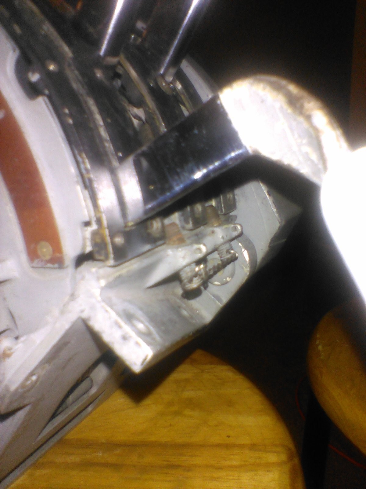
No, the forward edge is ~3/16" or so below the point where the shiny part ends (See photo Flap Lever 01). The flap lever pivot point appears to be behind the center point of the throttles. I can try to take a photo of it if you like. Salute, Punk
-
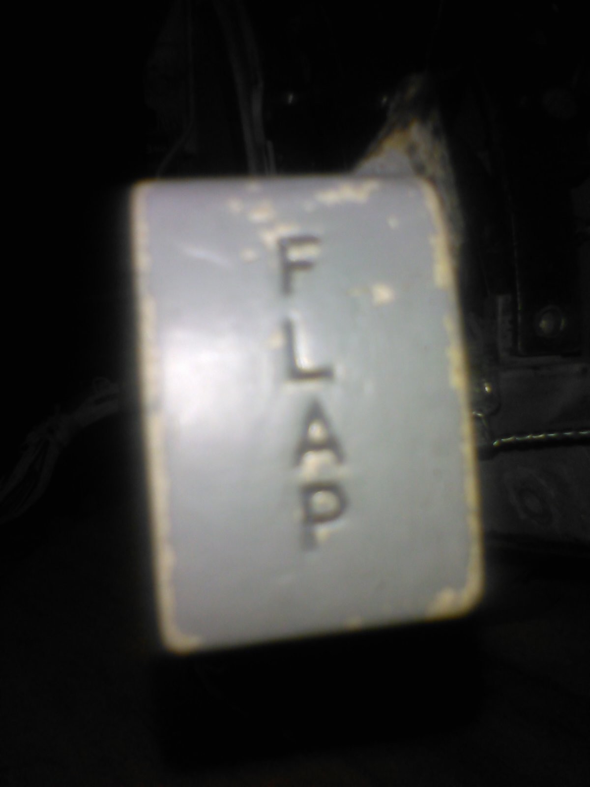
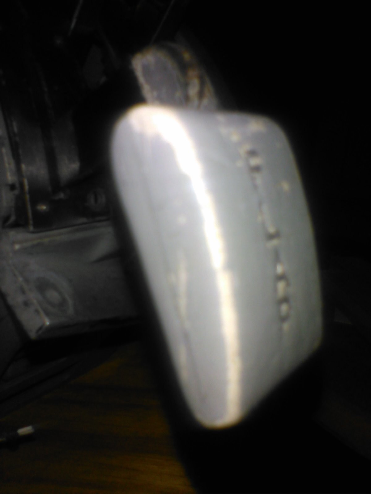
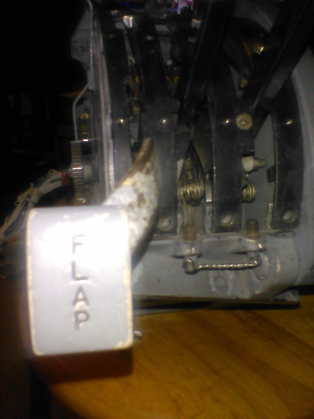
Psyko, Sorry for the delay. This coupled with lunatics work will hopefully help. Lever length above face plate at rear most point is ~1.5" of the shiny part of the lever at the point touching the back end of the flap throw to the discolored portion on the lever (See photo Flap Lever 01). It then twists rearward and away at ~ 45o angle. From the end point of the first measurement to the end of the lever is ~ 2 " (See photo Flap Lever 01 and 04) . The flap lever handle is secured by a single screw in the middle of the lever so that the lever reads FLAP down the center and is parallel to the throw of the lever (See photo Flap Lever 02) . Keep in mind the bottom of the handle is flat, the top is curved in an airfoil shape with the greatest amount of curve in the last 0.25' - 0.5' at the front of the handle (See photo Flap Lever 03). The trailing and leading edges are rounded (See photo Flap Lever 03). The dimensions of the handle are: Length: 1.5" Width: 1" Rear Thickness: ~0.5" Front thickness: ~0.25" Hope this is helpful and what you were looking for. Mumbles, Sorry for the delay. I am afraid what I thought might have been an ejection handle were ground pins. I may have one from another plane, I will look for it in case it is similar. Salute, Punk

-
psyko, Sorry, just finished up making some vids of the quadrant for a gentleman in France who is making his own. I will pull it back out and try to get your questions answered, but it might be a week or so, I am dealing with a lot of back pain right now. mumbles, I may have an ejection handle somewhere. I will look for it. I wish I had the others. Share what you find I hope. See above for time scale. Salute, Punk
-
I have not gotten around to any of this yet myself either, but some of the ideas I have come across for switch types include the use of the momentary switch as mentioned, Using a push button (think refrigerator light switch) so when the cover is lifted the switch activates, and the use of reed switches with magnets embedded in the switch cover. How many you fit into the area might limit how many functions. An Arduino and DCS Bios might be used, not sure how much of the software has been worked out though for the F-14. I have not used switch programs like RS Mapper in a while and unsure whether or not those programs are flexible enough to do what you are looking to do. Perhaps? Best of luck and please share what you learn. Salute, Punk
-

Change cockpit FOV without changing outside LOD distance?
punk replied to GunSlingerAUS's topic in DCS: F-14A & B
Having sat in the Santa Rosa Cat, to me the biggest difference is we are too low in the cockpit. You can see down the entire nose in the real one. The visibility over the nose was amazing. If they can ever work that out you will be blown away. Salute -
Sorry, don't have editing software on this machine, you should just need to use 1 row, the side by side poles should be pos and neg. If you want a single button to do more than 1 thing, use a different row for each action. Easiest way in my limited opinion. No electrician magician here, just a Joe.
-
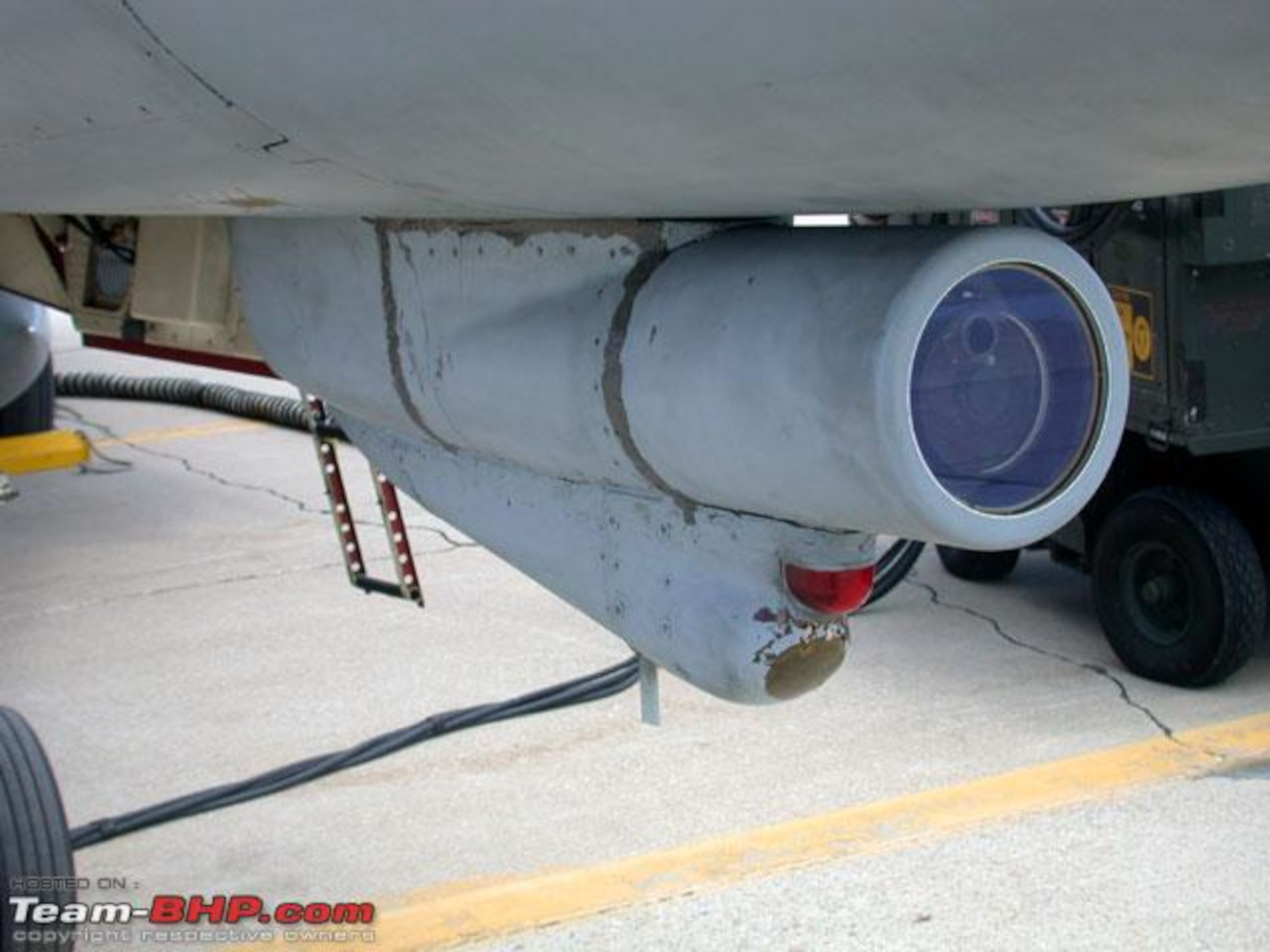
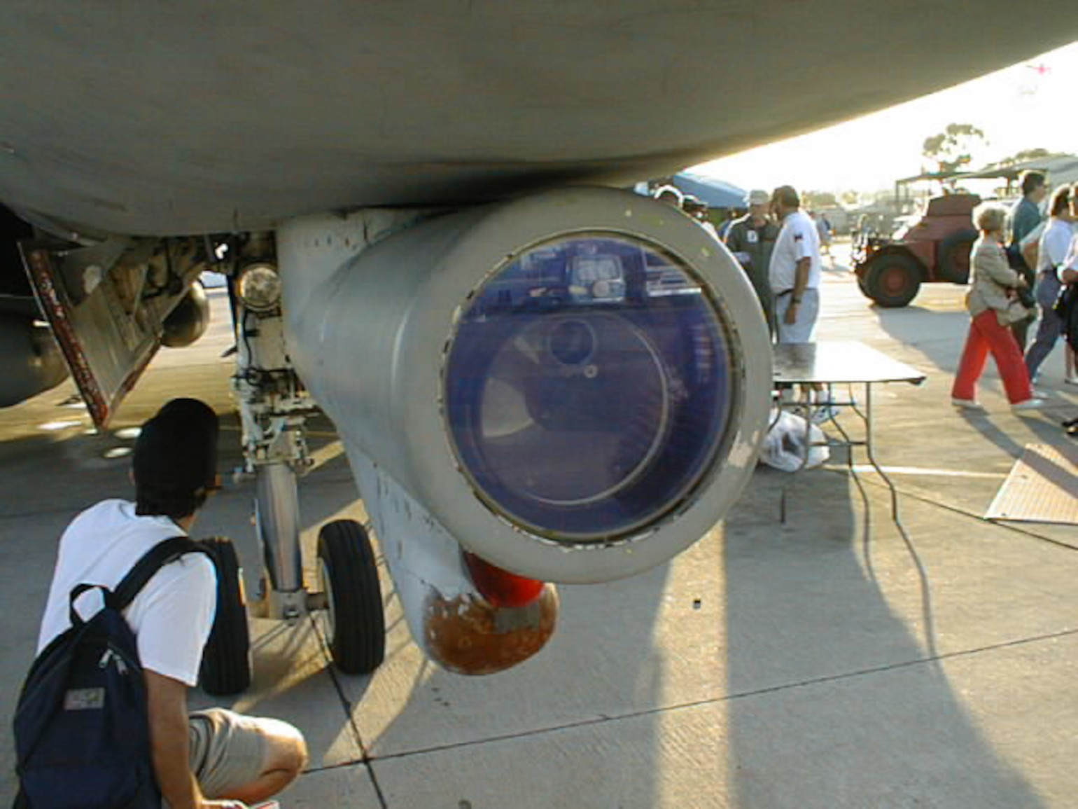
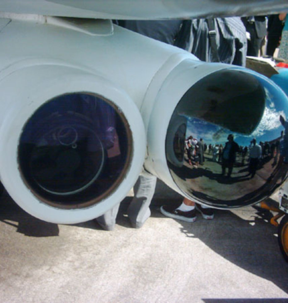
Unfortunately I only have an old flip phone with a cruddy camera so any images would be grainy and poor. I do have these online photos, hope they help a little better. If these aren't what you are looking for let me know in more detail and I will see what I can do to help. Salute, Punk
-
For anyone interested in seeing just how big the TCS is:
-
Hi Criminal, Leo Bodnar's boards make it very easy to have plug and play switches. If I can do it, any one can :). There are other brands out there, but I have found his the easiest to use for me. Perhaps Whiskey will share or sell his finished button plans. Salute, Punk
-
The metal part screws the cap on very securely. I look forward to seeing what you come up with. Salute, Punk
-
Here are some pics, only got a couple before power went out from storm that moved in. Let me know specific questions and I will answer best I can. I added one of a similar button bank as above, but it has 6 buttons. Length wise similar enough to get the job done. It is what I will be forced to use for the Air Source as I only have 2 of the 5 button banks. I may use one of the two 8 button banks I have from an A-6, but that will lengthen the panel quit a bit. Dunno. Let me know anything else I can do to help you out. Salute, Punk
-
The Real switch banks are much larger than than the ones listed above, but they should work just fine. I can post photos of a genuine one if you want. Salute, Punk
-
Sweet ride PSYKOnz. Glad I was able to help. Looking forward to following in your foot prints one of these days with my own pit. Salute, Punk