MetalGear_Honk
-
Posts
129 -
Joined
-
Last visited
Content Type
Profiles
Forums
Events
Everything posted by MetalGear_Honk
-

Open Source Joystick FFB / DIY FFB Joystick
MetalGear_Honk replied to Berniyh's topic in PC Hardware and Related Software
Hi Sounds like a Bug (or I have blocked the transfer to pc again) Definitely no problem with the Bootloader. BL problems lead always to "Device not recognized" I don't have a Compiler here but from Memory there should be a line ReportData->axis[0] = XAchse; Where ReportDAta is the Value send to PC And XAchse is the ADC Value XAche is set in the Einlesen function. Another idea is that you have the Descriptor not correct. That way you will not get any Values from the Device. You can try to set pin 9 to high. That should set all Buttons to "on" Hope that helps. MetalGear_Honk -
Open Source Joystick FFB / DIY FFB Joystick
MetalGear_Honk replied to Berniyh's topic in PC Hardware and Related Software
Hi yes that is correct. but i think the version that i have uploaded is still using the ADC from the Mega. so you need to conect the Pots to the corresponding pins on the ATMEGA32U directly. MetalGear_Honk -
Hi I did some more tests. All without Mods on the Gulf map. With small external tanks set up in Mission editor I get them empty. With big external tanks set up in Mission editor I get them full. MetalGear_Honk
-
Hi Checked fuel at 100% in Editor and in Arming /refueling screen. After Takeoff (when I switch to external Tank) caution light comes on immediately for X-Tank empty. MetalGeat_Honk
-
Hi When I enter a Mission with Drop Tanks they are empty. Can get them filled if I ask the ground crew to fill them. This might be the same bug as on the Viggen. Greetings MetalGear_Honk
-
Open Source Joystick FFB / DIY FFB Joystick
MetalGear_Honk replied to Berniyh's topic in PC Hardware and Related Software
Hi Thanks for the Formular. i will look into it as soon as i get back to my Test Lab. now that we are making some progress: has somebody else build a test setup? MetalGear_Honk -
Open Source Joystick FFB / DIY FFB Joystick
MetalGear_Honk replied to Berniyh's topic in PC Hardware and Related Software
ReHi works for me. maybe you are not allowed to download atachments? (new User?) or you have a add Blocker installed? here i Uploaded it again JOYSTICK_Test.zip MetalGear_Honk JOYSTICK_Test.zip -
Open Source Joystick FFB / DIY FFB Joystick
MetalGear_Honk replied to Berniyh's topic in PC Hardware and Related Software
Hi I have updated the FFB Software. For better testing it is now able to use X and Y Axis and the 32 Buttons. for the axis I have uses 4 Daisy chained Shift Registers PORTB4 = load = Pro Micro pin 8 PORTB5 = Data1 = Pro Micro pin 9 PORTE6 = clock = Pro Micro pin 7 for the Axis I use the internal ADC on ADC7 = X Axis = Pro Micro pin A0 ADC6 = Y Axis = Pro Micro pin A1 I will change that to an 16bit ADC as soon as I get a new one. (Kids and Microcontroller don't mix well) [ATTACH]181475[/ATTACH] If someone is Interested change of Hardware inputs can all be done in the "GetNextReport" Function Changing the ADC can be done in the "einLesen" function I haven’t changed the PWM or direction Pins. So these will work as in previous Versions. Another note: It is NOT possible to program the FFB Device using the Arduino IDE. The code generated is to slow. And I am Still not sure if the ATMega32U4 can handle the Calculations needed for sinus Effects. So if someone has a good way for Calculating Angles and sin Values with only Integers I am more than happy to integrate that in the source code. Greetings MetalGear_Honk -
Open Source Joystick FFB / DIY FFB Joystick
MetalGear_Honk replied to Berniyh's topic in PC Hardware and Related Software
Hi I am not sure that I understand what you are trying to archive. By using an USB-Hub: do you want to use two device classes INSIDE the controller? That is possible but not very easy as the 32u4 is to slow to host one FFB and one HID device. If you are planning in using two separate MCU than only the first part is of interest as a normal Joystick device is easy to do and has nothing to do with a FFB device. The second part about axis is also not clear to me. Do you want to mount Motors on all axis? 1. Direct input only supports 2 axis per PID / HID Device. 2. DCS has no support for Throttle FFB. 3. I am not sure if Pedal FFB is implemented in DCS (or any sim for that matter) now for some info’s: the Test Device (Big Block) that I have uploaded supports: 2 FFB axis 16bit (x/y Stick) 6 additional axis 16bit (Rudder, Throttle, ...) 32 Buttons 1bit 2 Hat switches 8directions that is also the maximum supported number of Functions for Windows Devices. DCS is able to address more Axis/Buttons but I think we should keep it compatible Greetings MetalGear_Honk -
Open Source Joystick FFB / DIY FFB Joystick
MetalGear_Honk replied to Berniyh's topic in PC Hardware and Related Software
Hi for using two Arduinos: we had this discusion twice already FFB x/y is send as one set like :30% Force in direction 230° a steerig weel needs only : 30% Force Positive MetalGear_Honk -
Open Source Joystick FFB / DIY FFB Joystick
MetalGear_Honk replied to Berniyh's topic in PC Hardware and Related Software
Hi with the Liking up a FFB Paddle du you mean to add another USB-Class to the controller? Or do you know a way to integrate more than 2 Axis into a FFB-Class? And would it be possible to give me/us some insight in your code? I would love to get a look at your effect calculations so I can copy those that I am not able to get working. :music_whistling: MetalGear_Honk -
Open Source Joystick FFB / DIY FFB Joystick
MetalGear_Honk replied to Berniyh's topic in PC Hardware and Related Software
Hi looks interesting. Are you using the Motors as counterweight? And how do you simulate near Stall speeds (loss of control Authority) how do you integrate the FFB communication in your controller? And what controller are you using? I have so many questions :-) are you willed to share some more information’s with us? MetalGear_Honk -
Open Source Joystick FFB / DIY FFB Joystick
MetalGear_Honk replied to Berniyh's topic in PC Hardware and Related Software
Hi sorry for the delay. The Project is still proceeding. I am working on the 16bit Axis and some shift registers to add some more Buttons. As soon as I have it working I will update the download. At that point it should be able to use is as a working stick. But don't expect too much. It is moving and all but not all is as expected. I am also working on the Gimbal design. I am happy with the version I printed. But I hope to add gears the design. There is still many Bugs and missing effects. MetalGear_Honk -
Hi Thanks I Was about to ask the same. MetalGear_Honk
-
Hi I have the same. voice stops afrer touchdown. MetalGear Honk
-
Open Source Joystick FFB / DIY FFB Joystick
MetalGear_Honk replied to Berniyh's topic in PC Hardware and Related Software
Hi here are the STL's it is very WIP you will need 1 Center1 1 Center3 2 Center4 1 Frame 4 bblocks 4 scews (2.5x12 spax) 8 Ballbearings 608 FFB_STL1.zip the gears and Motors are still missing. but can be mounted on the 8mm rod. MetalGear_Honk -
Open Source Joystick FFB / DIY FFB Joystick
MetalGear_Honk replied to Berniyh's topic in PC Hardware and Related Software
Hi I am using gears so I can get higher torkwith weaker/smaller Motors. Using weaker Motors for testing is helpingso that I can use an easier to Setup test board. (Only a dual H-Bridge) For the final Version everybody can usewhat suites him most. As Long as the Controller Output is supported. MetalGear_Honk -
Open Source Joystick FFB / DIY FFB Joystick
MetalGear_Honk replied to Berniyh's topic in PC Hardware and Related Software
Hi Sure but it will have to wait till Mondayas I am away for the Weekend. Another small Thing is that I didn't hadproduction in mind when I designed it. The most center parts do not fit in withoutsome heating and bending. I will draw some gears over the Weekendthe old style (pen and Paper) so I can calculate a bit and integrate that inthe test rig. Still not quite sure how fast the stickwill have to move. Another note: does anybody has an Ideawhat effects are supported by DCS? The main Goal is to integrate all, but thesupported ones are higher priority. MetalGear_Honk -
Open Source Joystick FFB / DIY FFB Joystick
MetalGear_Honk replied to Berniyh's topic in PC Hardware and Related Software
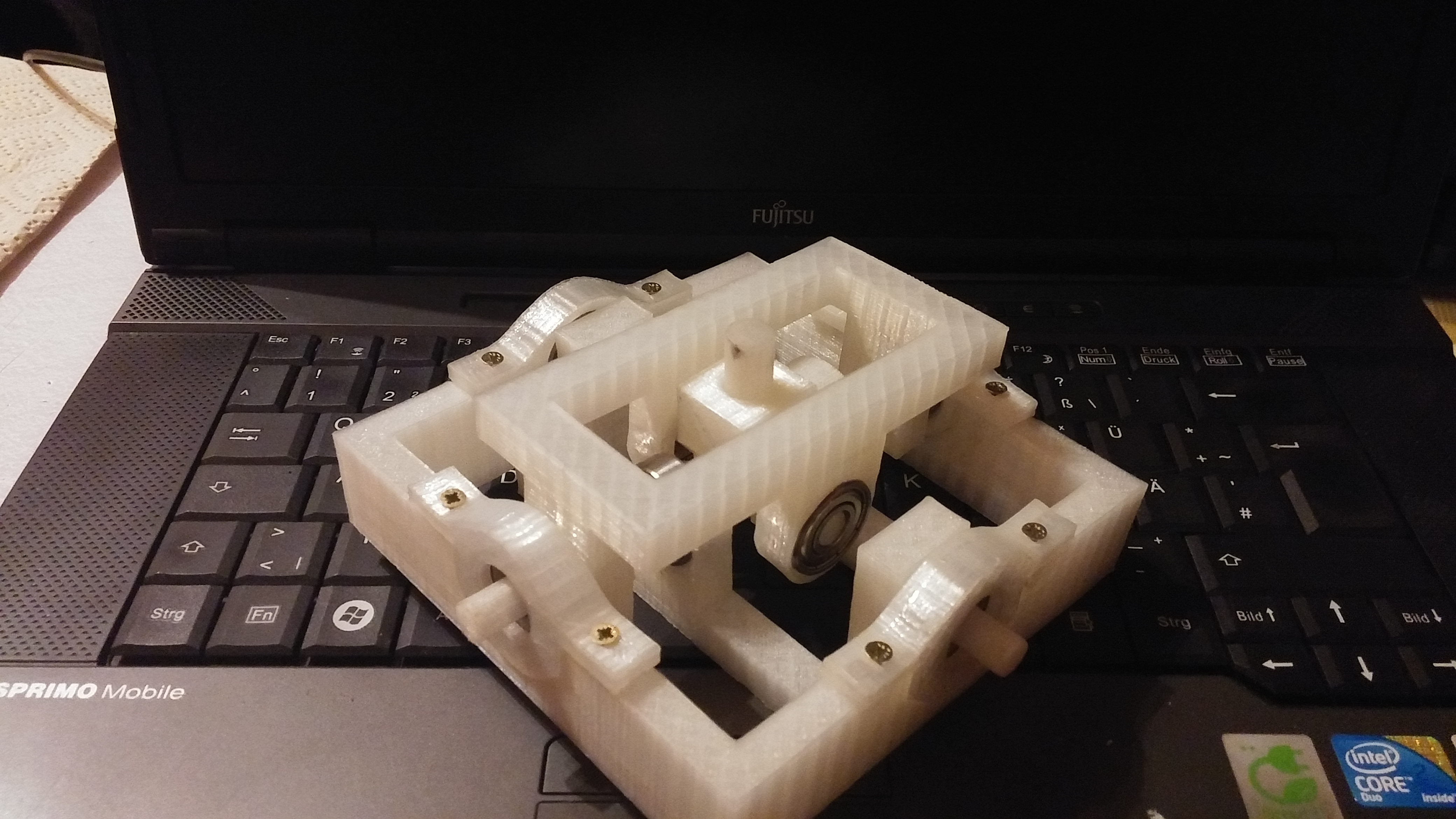
Hi Just a small heads up: I finished a Gimbal prototype. It is not meant to be used as finalVersion, as it is not very durable. 20171123_203833.jpg The Motors are not connected and the ones Itest with are quite weak. But for working on the Software it shoulddo. Speaking of Software. I am integrating anADS1115 in my design. As it gives 16bit Resolution for my Hal's. Is that ok fora General design? Or do we need a second Version with only the internal 10 ADC? MetalGear_Honk
-
Open Source Joystick FFB / DIY FFB Joystick
MetalGear_Honk replied to Berniyh's topic in PC Hardware and Related Software
Hi Looks good. For interacting: jep you need at last somepots (10k) and some LED and Resistors. That is the Basic Setup I am using mostof the time. I think I wrote the connections in thecode somewhere, but I can't find it at the Moment. The Motors are nice but to work on bugfixes it is not necessary. To test the affects you can downloadfedit.exe or ForceTest.exe One is a free tool and the other came withthe direct Input. (Don’t ask me witch is witch) MetalGear_Honk -
Open Source Joystick FFB / DIY FFB Joystick
MetalGear_Honk replied to Berniyh's topic in PC Hardware and Related Software
Hi here is the post about Programming a Pro Micro -
Open Source Joystick FFB / DIY FFB Joystick
MetalGear_Honk replied to Berniyh's topic in PC Hardware and Related Software
Hi What exactly are you trying? Starting with MC's? Or run the code I made? For getting used to a MicroC (using yourController): 1. Download Arduino 2. Plugin you Controller 3. set Arduino to your Serial where youController is plugged in. 4. Run some test codes blink is recommended. For using my code: Follow the instructions I gave earlier. Edit: can someone tell me how fast the stickmovement Need to be? maybe someone with a SideWinder can tell us how fast it travels the Maximum way? MetalGear_Honk -
Open Source Joystick FFB / DIY FFB Joystick
MetalGear_Honk replied to Berniyh's topic in PC Hardware and Related Software
Hi Not much News in Software. I am working on my mechanical test Setup. For the OSW we had that discussionalready. The Software is not compatible for two axis. Another Point is the third axis (pedals) wewere talking about. That is not possible as well. Only twoaxis are supported by DirectX. Here are some Info’s about ffb: https://msdn.microsoft.com/en-us/library/windows/desktop/bb153254(v=vs.85).aspx http://www.usb.org/developers/hidpage/pid1_01.pdf And again: We are not integrating with anyflightsim! The Developers are offering all Forces when they offer FFB support. Sowe do not need to read any data from the sim itself. MetalGear_Honk -
Open Source Joystick FFB / DIY FFB Joystick
MetalGear_Honk replied to Berniyh's topic in PC Hardware and Related Software
Hi I use far weaker Motors at the Moment. 93mNm. but with some 21000rpm. Using a 10:1 Gear. That is still not enough. On top of that we will get a big Lever that will reduce our force. As for my comment about the "weak" Motor. It is compared to otherSteppers. Steppers have more Torque by design that DC Motors. So your comment abouttorque to Money Ratio is very valid. It has just not enough torque for the FFBdesign that I am working on. MetalGear_Honk -
Open Source Joystick FFB / DIY FFB Joystick
MetalGear_Honk replied to Berniyh's topic in PC Hardware and Related Software
Hi @Pinello That is a Stepper Motor. (And a very Weakone too) We had a discussion about what Motor touse some Pages Earlier. If I recall it correctly we decided to usea Brushless DC Motor with a Gearbox. Note: no worm gear. @Slartibartfast These Magnetic FFBs look interesting. But Ithink it is not very suitable for this OSFFB. If I understand it correctly theForces are distributed over the various electromagnets. And therefore we wouldnot be able to use different Setups. Not even different Coil designs as itwould affect the Magnetic field. For the Gimbal itself. I made some testsand I think I have something useful. It is basically a crossover for FlightsimVR's Design and the original SideWinder. I made a mistake in one of the Center piecesso it will take a few more days to replace it (I run out of Aluminum). Next step will be the gear and Motor. I tried the higher Voltage and it looks promising. My test Motors are 12V DC and I am runningthem now on 24V DC Most of the time they stay below the 12Vwith some Spikes up to 24V But my Scope is not the Fastest so I cannottell for sure. MetalGear_Honk