Figaro9
-
Posts
117 -
Joined
-
Last visited
Content Type
Profiles
Forums
Events
Everything posted by Figaro9
-
 Yes, that's how I thought about it too. 4.7 alpha is close to the best L/D ratio. It is possible that drag and lift difference becomes large enough above that to outweigh the lifting effect of the canted stab. Pure speculation though... But it might also explain why the roll rate increases with higher AOA.
 -
Probably that one?

-
This behavior is not speed but AOA-dependent according my today’s tests.Above ~4.7 alpha the roll is in direction of the rudder input. Bellow ~ 4.7 roll is very slightly in the opposite direction. Can’t tell why. Probably the outboard angled stabilizers play a role here…
-
Check the srv-info-changelog on the mob discord. It was definitely a wake turb you caught It is turned off again.
-
Sure, it is a design for a specific spectrum (5000h, max 9g, A/A only, 40’ sortie, 30 years lifetime). In addition to the structure and software, other critical parts were strengthened like landing gear uplock pawls, fuel cell retaining clips and wing fold hinges.
-
The swiss do have a 7.5g peace time limit, but the aircraft is 9g rated. Here is a vid with a demo pilot. https://www.youtube.com/watch?v=xS2LwzbjWhs&t=952s They have a reinforced structure using titanium instead of aluminium in some parts and a customized 9g flight control software. https://www.slideserve.com/kaspar/strategic-engineering-designing-systems-for-an-uncertain-future-powerpoint-ppt-presentation
-
Exactly the same as non fbw-aircraft like f5,m1, f14 ect. can be modeled above their g-limits (outside em-charts) in game. Search for the Flight model principles document. Ed shows how the magic potion is prepared. A pinch of drag polar (preferably data from a rw wind tunnel), a bit of thrust (if possible installed) and above all a lot of math and physics... Em charts are not the basis of the fm, it is a result. There are also programs that can do the math. http://www.alr-aerospace.ch/index.php?id=fighter-performance-mission-analysis By the way, great update ED. Thanks for that.
-
Do you use bushmannis miz? Check temperature?
-
True, but compressor stalls still happened sometimes. Here is an excerpt from the flight accident report on how the j-5235 was lost: During this training flight on 14. october 2015, the F/A-18D Hornet was to practice air combat against two F-5s. When the hornet reached the minimum safety altitude (so-called hard deck), the pilot changed the target. He wanted to pull away to the upper right with full afterburner deployment in order to fight the other F-5. The aircraft began to turn to the left with an unintentional rolling motion. The pilot responded by changing control from right to left to stop the roll before entering the clouds. At 11.29 a.m. and at an altitude of approx. 2,280 m above sea level, the pilot received the acoustic warning "engine left, engine left" and at the same time the warning "L STALL" (stall in the left engine) was shown on the cockpit display. The pilot did not take the immediate action prescribed for this case. (In this case, the flight manual stipulates that the affected engine should be put into idle by changing the position of the power lever, which leads to a reduction of the pressure in the engine and thus to the elimination of the stall as the cause of the power loss. ) As a result, the aircraft continued to lose altitude and dived into the clouds. A few seconds later, at an altitude of approx. 1,855 m above sea level, the pilot activated the ejection seat The technical expert concludes in his report that a combination of various factors led to the stall in the left engine and ultimately to the loss of the stable flight attitude necessary for a possible further flight with only one engine: 1. flight at very low speeds and thus high angles of attack; 2. aggressive maneuvering with rapid changes in angle of attack and abrupt power lever movements. Here is another one, which was recovered the proper way… https://www.youtube.com/watch?v=mFLbAUkCNFY
-
According to bn, Cg is a little too far ahead in edf18 iirc, which leads to too high takeoff speeds.
-
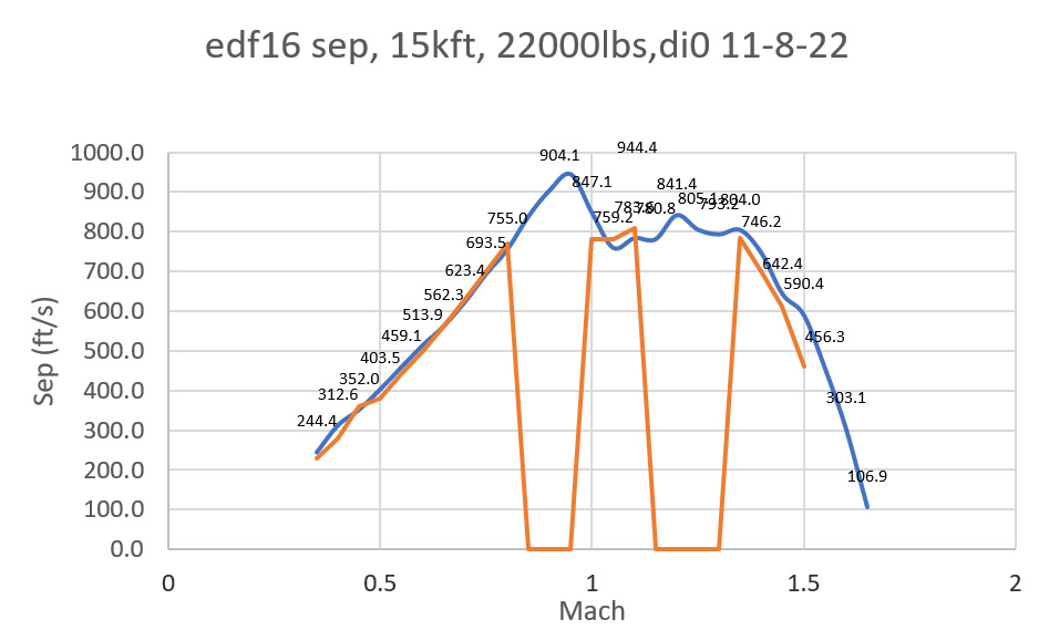
acceleration looks good to me, at least for di0 22000lbs at 15kft. blue is sep for edf16, orange for haf block 50. Where the orange line indicates 0sep (m0.85-1.0, 1.15-1.3), no correct sep-value can be read from the chart and I do not want to speculate here. keep in mind that there is some tolerance in measuring sep in game and also in interpreting charts. Overall it is very close.
-
Check also: https://tawdcs.org/radar-f15/
-
correct as-is When will they fix the flight model?
Figaro9 replied to Awesomejlee's topic in Bugs and Problems
OPs plots are from another game as already correctly stated above. And they were proven incorrect when the famous gao report was released. Mstr in those game-plots are 2dps (!) below the official dod figures. Mstr for the epe hornet is rather close to the -200sep curve (33325lbs/ 2*2 FE). Those gamers were lacking 2 degreese per second compared to the real jet! EDs performance in that regard is 'correct as is' based on available data. -
correct as is G-limiter allows gross over-g on the airframe
Figaro9 replied to Rissala's topic in Bugs and Problems
Watch this. https://www.youtube.com/watch?v=a-gPWlODKCY 01:21:58 10.5g on a Hornet It is operator technique, you can’t blame the aircraft. -
Well, guess that plot is for the f18 with the 402 engine. 33’325lbs corresponds to a 7.33g-limit Max sustained speed at 15kft is ~m1.4 (gao & eidetics). Speed design limit is m1.5 (gao & eidetics) 1g Sep looks congruent too. While for the f18 with 400 engines max speed is m1.27 at 15kft, 2/2, 32500 lbs
-
those rates in the graph are the rates I get. I do not use the info bar but the attached scripted missions. The turn rates are scripted into the dcs logs. So is sep, aoa ect. At 33693 FCS does limit g to 7.3g max according the fcs page in the pit. 7.5 g like displayed in the info bar according yout pic is not possible. So there might be a difference between fcs g-meter and the gz displayed in the info bar. Therfore ist probably better to use the attached mission (Standard day), cause turn rates are measured in game and you do not have to do math via g-loadings... Sustained turn rate test flight f18.miz instantaneous turn rate test flight f18.miz
-
Did more itr tests with the scripted mission and I put it over a public nasa f-18 em chart and a tr vs bleed-rate graph (green=nasa, blue=dcs). Itr: Lift limit line looks quite good but is slightly left. Max itr looks good too, speed bleed at corner is quite a bit too low (but so is aoa (~25°) @ m0.65) but good below m0.45. Str : mstr is perfect. Str is slightly low between m0.5 and 0.7 and slightly high above m0.85. I would say, good work so far.. https://ntrs.nasa.gov/citations/19950007836
-
I like anecdotes. Find me an sme who did acceleration tests in dcs … and reports a bug… There is a great scripted mission by bushmanni to do so in dcs. According sources, the f18c (lot19) sep at 10kft is 695ft/s at m 0.9 (33325lbs, 2a9+2a120). In game, I get 668ft/s . ED is doing a great job and is getting closer and closer. If you are looking for a challenge, do a climb & acceleration test and compare the results to rw figures.the hornet lot 20 should climb and accelerate from brake release to 49’000ft and mach 1.4 (2a9, 2a120, 100 % fuel, standard atm.) , in 4 minutes and 9 seconds…. So far it I takes 4’06”. . What do you get? As for air quake: you need to know that the f16 (and mig 29) starts a 1vs1 fight with much more % internal fuel than the f18 because they burn internal fuel much faster on burner. That doesn’t really help…
-
correct as is Spin recovery engages when pirouette parameters are met
Figaro9 replied to Hulkbust44's topic in Bugs and Problems
Yup, that happens in dcs when you split throttles (and apply pirouette inputs at the same time). The arrows show up immediately although they should not while pirouette input are held (for 25s) according below linked thesis. For spin recovery training (v10.7), the initially applied pirouette inputs must be removed (after 1.5 turns), otherwise the arrows will not show up. The f18 with v 10.7 should exit spin even with neutralized control inputs…delayed though. But the direction of the arrows is right as far as I see: „Antispin control input involves moving the control stick laterally in the direction of the spin arrows. Normally, this direction is into the direction of the spin if the spin is up-right. „ https://trace.tennessee.edu/cgi/viewcontent.cgi?article=3738&context=utk_gradthes -
Afaik ed is aware that aoa needs tweaks. Here is a thesis on f-18 spin demo procedures. According to that document the pirouette works best at aoa ~45° and ~ 150kts. We do not get there atm in dcs. There are graphs showing yaw, roll and pitch rates as well as aoa. Aoa goes up to more than 60°. And yaw rates are up to 50° if thrust is split (max/idle). Yaw rate is higher too in dcs if you do so, but if you try max/idle, you enter a unrecoverable flat spin and the arrows show up almost immediately… With mil/idle split set I managed to do a full 360° pirouette in slightly more than 9 seconds, which means an average turn rate of almost 40°/s. Without split-throttles it is approx 3 seconds more. There is some data available to improve aoa capability (and pirouette logic) in dcs. https://trace.tennessee.edu/cgi/viewcontent.cgi?article=3738&context=utk_gradthes
-
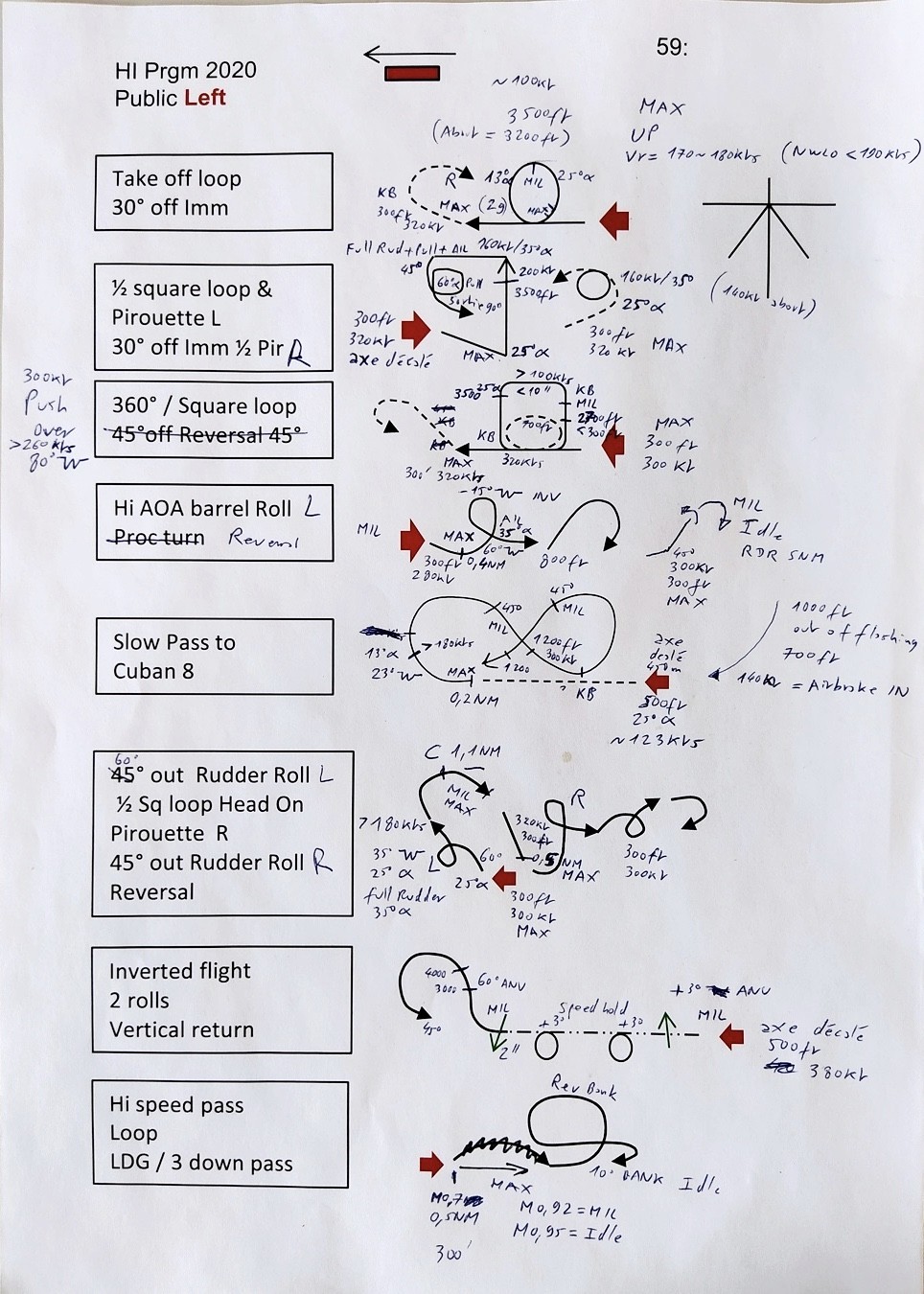
Heres a demo program with pilot notes presented by the saf display team showing target altitudes, airspeeds, aoa and throttle settings for different maneuvers. https://de-de.facebook.com/swisshornetdisplayteam/ We sould be able to pull 45° Aoa at 160kts in the lot20 before we apply pirouette input. By pulling to an aoa of 60° the nose would rise ~30° above the horizon (while the flight path goes down 30°). For more impressive pirouettes we need more realistic aoa capabilites.
-
If you do not have data, search the web, or books etc. try to bring yourself to the same level of knowledge as ed . There is plenty of info, not as easy to interpret as em-plots, but tons of nasa data (drag, lift, polars, thrust data, sep, envelopes, etc) for the f18, even maneuver charts. Probably far more than for many other existing modules. Enough to built a high fidelity module for scientists and developers like ed. Not to forget the sme inputs. If a fm does not behave as you expect, your expectations might be wrong. Or ed and independent scientists are. I tend to trust the latter, math based on aerodynamic (nasa) data. Call me naive. ED knows where the fm needs tweaks and there should come a fm update „soon“. I expect slightly higher sep, slightly better aoa-capability and moderate higher speed bleeds at corner based on my tests against public available data. And (marginal to) almost no str or itr changes. But probably my sources and expectations are wrong too . We will see. But this is not the f18 thread right?
-
Yes, I think there were changes, but it seem closer to rw now. Iˋd say the pirouette works in dcs, but we probably still lack of aoa capability although some improvements have been made. The maneuver in airshows is described in the us tac demo manual, only for E model though. Start 800ft above ground, 350 kts Full Ab, pull 5-6g into the vertical. At 5000ft agl full aft stick and hold 35° aoa . You do get 35° in dcs only below ~ 200 kts, I can not do a constant aoa loop over the top so far at 35° aoa. fm needs probably some tweak here? Capture 175 kts at 35° aoa and when 40-50° nose low, apply pirouette input. Pirouette works best (for the e model) at 175kts according above mentioned manual. I can hold approx 150 kts at 35° aoa in the trk Hold 35° aoa Remove Inputs. I have red that in the lot 20 they initiate the pirouette inputs at 40° aoa.... pirouette 10-21.trk
-
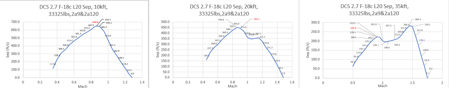
Good work curly Is this probably the reason why sep is still slightly low at m0.9 in game (m0.9, 33325lbs, 2a9+2a120)? 10kft: dcs 647ft/s , gao 699ft/s 20kft: dcs 444ft/s, gao 512 ft/s 35kft: dcs 223 ft/s, gao 247 ft/s Here is the mission if anyone wants to check the above figures. Simply do a 1g acceleration test at the desired altitude. SEP is printed in the logs as m/s and m/s2, which can be converted to ft/s or kts/s to check with gao numbers and envelope… acceleration f18.miz
-
There is zero interpretation on my part regarding those numbers above for the F18 sep nor any chart reading. It is simply copy paste of numbers given by the dod in hearings 1999. That’s the level of precision those guys use to work. And it greatly shows that there is not a easy answer to the f14/f18 acceleration question since there are many variants and lots. And the numbers for the f14 are from the dod (1985 hearings) too. It is however a graph that compares the d with the a model. You can therefore compare different sep states at different mach numbers. Peak acceleration at M0.9 is marked as 640ft/s for the d (what a lousy level of precision they worked back in 85) . And it shows that the d model only has a higher sep up to ~M 1.050001. When I interpret that chart, I do it even more precisely and therefore mark them with a ~ , like: Sep at 10kft , Mach 0.6, Standard day, 60% Fuel: F-14A TF 30: Ps ~320,0000 ft/s (4 /4 ) F-14D F110 : Ps ~405,0001 ft/s (4 /4 ) Sep at 10kft , Mach 1.2, Standard day, 60% Fuel: F-14A TF 30: Ps ~220, 0002 ft/s (4 /4 ) F-14D F110 : Ps ~200,0000 ft/s (4 /4) Since there is no graph I can not give you corresponding read outs for the f18. But there is an envelope chart in the gao report for the epe Hornet. With some math you can convert the sep from kts/s to ft/s. But the level of precision doing so would not be on par with the above data, so I Iet it be...