Sergey_Pe
-
Posts
82 -
Joined
-
Last visited
1 Follower
-
Well, quite frustrating since your programming sequence looks correct. OK; for a start let's check if your chips are really working in analog mode. After you wire up VCC, OUT and GROUND and rotate the axis, does the OUT signal change? The second question- have you defined the direction of axis rotation by shorting the DIR pin either to VCC or to GROUND as described in the Wiki? BTW- merry Christmas and happy New Year!
-
If the chip is really a 74HC165 (the description says serial input/ parallel output while it should be the opposite)- yes, it can be used with both controllers.
-
Absolutely correct. But this is a thread about MMJoy2, not TM controller, and the guy who asked about the boards didn't mention TM at all. So it might be an easier solution, providing that MMJoy is working with both shift register types.
-
Or you can simply buy THIS or THIS.
-
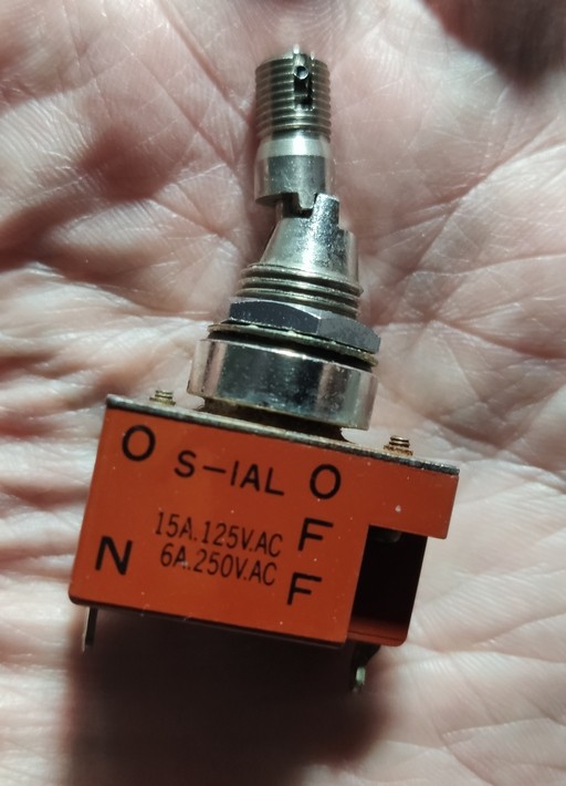
T80 switches from Salecom are quite good, being an almost 1:1 copy of C&K 7000 series. But be careful- there is a lot of "clones" of a real T80 series at Aliexpress that might be quite unreliable (I've seen a lot of these clones breaking down). To be sure look for a "Salecom T80" at Aliexpress; the real ones have a "Salecom" logo on the switch body, as in your picture. Speaking of the other options- this is a locking switch that is being used in real planes (like Cessna); both the 2-position and 3-position versions are available, but they may be quite expensive/ hard to find. I've managed to pick up both versions unused on eBay together with a Cessna knob.

-
An encoder is essentially a pair of buttons. And as with the regular buttons, you can connect them to the shift register inputs; diodes are not required but the pullup resistors are. This way you'll get two physical buttons that can be defined as encoders in the "Joystick Buttons" tab. I'm just guessing here as I never connected a 3008 to MMJoy myself, but the logic is that the shift registers are not sharing the data line with the SPI-connected peripherals. For each shift register (single or daisy-chained) you are defining the CS and Data pins in the configurator separately. However if you use, say, the TLE50XX sensors for the axes then these sensor boards WILL share the MOSI line with the 3008. Still (as mentioned in one of the posts above) I'd recommend to move to a FreeJoy project based on a BluePill (STM32) board. It's way more advanced/ stable and offers an excellent online manual (in English as well). Just an example- with the FreeJoy you don't need the pullup resistors for the buttons/ shift registers. What's also important is that the project is constantly evolving with more functions added by the community requests.
-
Well, I've finally installed an AS5600 magnetic sensor into Saitek throttle. A small round magnet (approximately the diameter of a lever bearing which was cut flush with the lever body) was super-glued to the lever, working as a new bearing. A small circular PCB with AS5600 was hot-glued in place of a stock resistor as seen on the picture. Then AS5600 was calibrated to provide a full output voltage swing within a lever movement angle. Of course it works like a charm, as expected. The trick is to find a a magnet with the appropriate diameter (I had one as a leftover from one of the old projects).
-
No it's not. How did you define these buttons in MMJoy configurator- as "Button (norm)"?
-
Keyboard doesn't have right side Win key. Help?
Sergey_Pe replied to -0303-'s topic in PC Hardware and Related Software
As opposed to Shift, Ctrl and Alt keys, the Win key is typically not supposed to be duplicated on the right side of the keyboard- it depends on the manufacturer. If you don't want to use an additional app, then buying a different keyboard is the only option. -
Honeycomb Bravo Throttle ?
Sergey_Pe replied to packman2002's topic in PC Hardware and Related Software
It's an encoder. -
No, because it was an initial small batch for Gunfighter base owners. Full-scale production will start right after the Chinese Year.
-
Debolestis Shapeways shop
Sergey_Pe replied to debolestis's topic in PC Hardware and Related Software
Sorry, you are right- I've automatically mentioned the old connector as I'm still using it in all my VKB gear: it's more reliable than the current 3-pin proprietary version. Not sure how easy/ difficult it would be to install a mating part into a Gladiator base... The info about removing the connector (both Rev. A and Rev. B) from the adapter is valid anyway. -
Debolestis Shapeways shop
Sergey_Pe replied to debolestis's topic in PC Hardware and Related Software
No, it's not. In earlier versions there was a threaded pin that had to be screwed out to free the connector, now it's just a rubber block that holds the connector in place and is very easy to remove. And then the connector goes out. Besides, the connector itself can be purchased from AliExpress or eBay- here is the link. -
Gunfighter Pro center calibration slowly drifts problem
Sergey_Pe replied to jasonstory44's topic in VKB-SIM Flight Gear
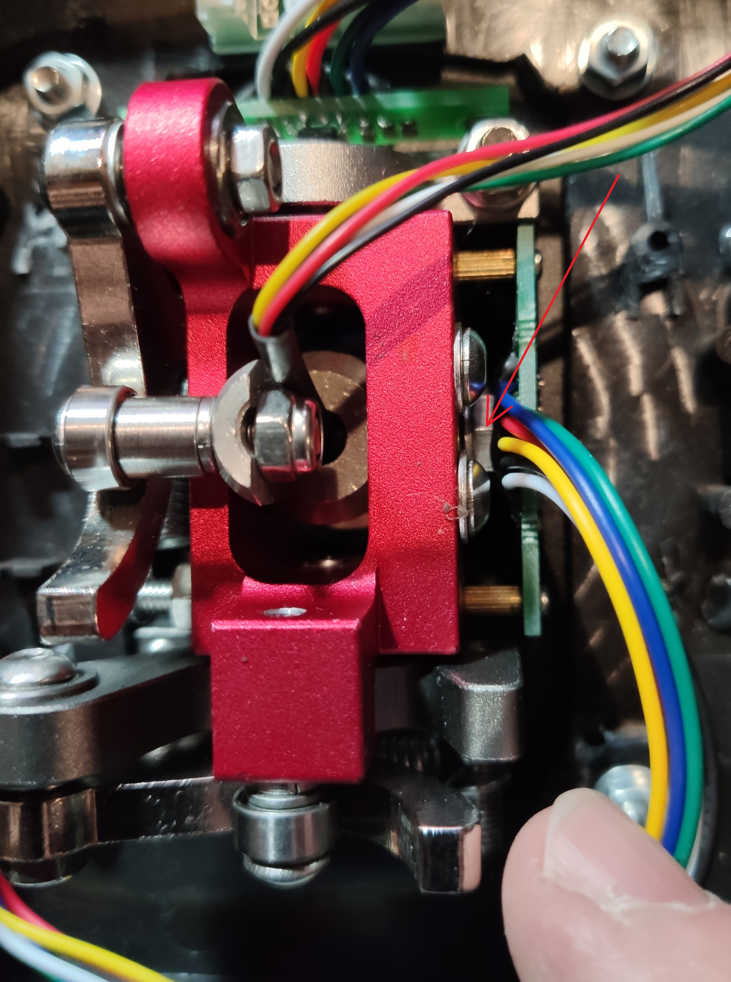
In case of VKB everything can be fixed (seriously!). The magnets on the axes that are used in the sensors are glues to the shafts (threaded pins) of the axis bearings. In extremely rare cases (especially with an extension/ heavy grip/ strong springs) one of the shafts can get loose so that the shaft + magnet start rotating, hence the calibration shift. You'll need to take the gimbal mechanism out of the body, remove a Y-sensor (2 screws) and tighten the nut that holds the Y-axis shaft in place. Here is the photo; I don't have a Gunfighter, this is a previous VKB gimbal, but it's very similar (just the dampers are missing). The nut that you need to tighten is marked with an arrow.
-
Sokol is keeping an eye on everything interesting and useful coming up in simulation area. And he is always eager to share his findings which is great!