ChockP51
-
Posts
30 -
Joined
-
Last visited
-
Feedback Thread - F-14 Tomcat patch Jan 27th 2022
ChockP51 replied to IronMike's topic in DCS: F-14A & B
Agreed. It would be best to have a numerical result compare with some sample of experiment data with grid dependent study. Different grid topology may provide a different result as well. Refined hexahedral cell in wake region may provide a more accurate drag data. I had on instance where wake region is not sufficiently dense and drag value shot way up. However, it is hard to obtain such data (Ie drag polar wrt mach and Re) and white paper reference didn't provide such data. -
Feedback Thread - F-14 Tomcat patch Jan 27th 2022
ChockP51 replied to IronMike's topic in DCS: F-14A & B
Interesting didn’t know that the plume effect wasn’t include. The plume normally increase the pressure at the base and thus greatly reduced drag coefficient when the motor is firing. However, these drop in base pressure depend on plume strength and it could be the other way round as well -
Feedback Thread - F-14 Tomcat patch Jan 27th 2022
ChockP51 replied to IronMike's topic in DCS: F-14A & B
Judging from the mesh preview and post process figure, I believe they use ANSYS fluent. The angle of attack can be adjusted by changing velocity component at the inlet boundary or rotating the mesh but that’s not the usual way we do it. -
[RESOLVED] AIM-54 inconsistency with CFD whitepaper
ChockP51 replied to dundun92's topic in Bugs and Problems
As a person who has some experience with CFD, I would like to address that CFD result is not a holy grail and it is always the best to use the experiment data if it is available. Especially in calculating maximum lift or drag survey where it is not uncommon to have a drag discrepancy with wind tunnel result, sometime as much as 10-20% in transonic region. There are many factor that could influence the result from CFD especially the mesh quality even though HB paper stated that they did a grid independent study already which should be alright. Sure if the mesh and grid resolution can be increase (to the point of LES or DNS turbulence model) the accuracy would likely be better but that is far beyond what is possible with a computing power today. Thus CFD result should be adjusted accordingly to ensure a proper behavior observed in real life experiment or available testing reports. -
What wikipedia imply is the pitching authority has been hamper by the aft shift in center of pressure due to shockwave in high speed flight (read above mach 1.5) on main wing and reduce pitch control power on the elevator itself due to the shockwave on elevator thus the elevator can’t really generate enough pitch control power to achieve 7.5G until glove vane was put in place. It doesn’t imply max G capability that airframe can generate.
-
Another CTD with STT lock on Su25 with AIM54A-MK60 in GAW today in F-14A. Here is the log. dcs.log-20210213-091011.zip
-
I think this is the same issue!. I wasn't able to check the tacview since the file is corrupts but it certainly most likely that I was locking Su25.
-
Greeting, Lately I got a frequent CTD while in PAL mode or STTing and looking down situation in MP (GAW to be specific). It doesn't always CTD when I STT or PAL, but every time it CTD I was in STT or PAL mode. Tried repair and delete fxo & metashader already but this doesn't seems to help. Here is the couple recent crash log. Best regards. dcs.log-20210212-150453.zip dcs.log-20210212-135253.zip
-
Would be a day 1 purchase for me. This thread is very interesting on F111 capability. https://forums.eagle.ru/forum/englis...-it-b?t=258958
-
Around mill rpm. Idle lockup work flawlessly.
-
I got some "bang" compressor stall too. Happened occasionally when I dive from high altitude with throttle idle and pull some moderate G (3 to 7 g-ish) at around Mach 1.2-1.4. Engine operate in PRI mode and Ramp is not stow.
-
Thank you sir for your detailed answer. Yeah I think we look are the same Preliminary technical Order and you pretty much clear most of my questions. It’s a shame that some cool switch and feature didn’t make it to the operation plane such as autopilot mach hold function and wing sweep schedule program selector. 3. For F-14B NATOPS it doesn’t explicitly said that the maneuver flap can be manually extend with wings sweep less than 50 deg. In fact the figure 2-51 in F14B NATOPS show where maneuver flap can be extend. At SL F-14B maneuver flap will retract at around M0.6 which is about wing sweep angle of 21 degree. Granted, the PTO F14A has the maneuver flap schedule limit as well. However, the graph is with respect of dynamic pressure.
-
Lately, I went through some F-14A material from Grumman. Compare to a NATOPS F-14B& D available publicly, I went through and here I have some questions about the difference. 1. F-14A show a figure of bleed door schedule but in F-14B NATOPS mention that these bleed door always open. Is this a change related to engine-intake matching? and if we bleed door open is it possible to see it open from the outside ? 2. F-14A mention that there is a switch in the cockpit that allows a pilot to select wing sweep program schedule that maximizes Ps or CLMax. Is this switch persist in operation aircraft? 3. F-14A allows maneuver flaps to be extended up to sweep angle 50 degrees but our F-14B & NATOPS seems to allow extended maneuver flap only at the most forward sweep angle. 4. Will we have the power trim indicator gauge available in our F-14A?
-
The idle lockup is there to smoothen out the deceleration process and make a life of air intake engineer a little bit easier. What happened when the engine rpm goes idle is a sudden decrease in mass flow rate to the engine. This mean the intake has to dump unwanted unwanted air to somewhere else. For example, concorde has the spill door at the inlet floor to dump this unnecessary air if it has to perform an emergency descend at mach 2.0. If air intake configuration left uncheck (ie, config for mill/max power) or is not properly config to cope with a sudden reduced in mass flow, the shock wave system inside the intake has to be stronger to decelerate the flow fast enough to match the low mass flow demand from the engine. The unwanted byproduct of stronger shockwave is a “dirty” or turbulence air fed toward the engine. This dirty air will reduced a compressor stall margin or even worst stall the engine. You can try stow the intake ramp in HB DCS F14 and fly supersonic to see what it is like. In the extreme case, the shockwave will become so strong that it will detached from the intake ramp and become unstart. Unstart may or may not solve itself depend on intake configuration and occasionally required an air intake controller to perform some action to return the flow to its original state. If the idle lock up is used, the sudden decrease in mass flow issue will be eliminated entirely. Here is a little story from Concorde side on their state of the art intake system from pprune and the purpose of idle lockup protection. “If I may, I would now like to mention the 'some oil lamps and diesel oil' story. This is a true story told to me by Dr Ted Talbot, the father of the Concorde Intake, brilliant aerodynamicist and all round amazing gentleman. Ted had been invited in 1975 to speak to the US test pilots at Edwards Air Force Base in California, and after he landed he was invited to take a tour through one of the top secret hangars there, and in this hangar were a few glistening Mach 2.5 design B1A development aircraft. Now Ted had heard that Rockwell were having major difficulties with the engine intakes, and obviously had more than a passing interest in such things, and was allowed to take a close look. Just above and slightly forward of each intake he observed several beautiful made precision total pressure probes mounted under the wings, and although he had a good idea what they were for, said nothing at the time. That evening, Ted gives his presentation speech to the assembled Test pilots, explaining in fair detail how the Concorde engine intake operated, and that the fact that unlike most other supersonic designs, the engine power was more or less freely variable at Mach 2 and above, even to the extent that if necessary the throttle could be closed all the way to the idle stop. There allegedly many gasps of amazement and disbelief in the room at this, and one B1A pilot was heard to ask his boss 'why the hell can't WE do that John'?. (It should be borne in mind here that the 'traditional' way of slowing down Mach 2+ aircraft is not to touch the throttles initially, and just cut the afterburners. If you don't do it this way many designs will drive into unstart and even flame-out). After the audience had asked Ted several questions about Concorde, Ted was then invited to ask the assembled USAF and Grumman personnel about the B1A programme, which would be honestly answered within the confines of security considerations. Ted said that he only had one real point to raise; 'I see that you are having major difficulties with wing boundary level interference at the engine inlets'. There was now a gasp of horror from various members of the USAF entourage, 'That's top secret, how the hell do you know that?'. Ted chortled 'it's easy, I saw that you have a multitude of precision pressure sensors under the wing forward of the intakes, that I assume are to measure the wing boundary flows'. Ted then unhelpfully comes up with 'Oh, and you've got the design completely wrong, your intakes are mounted sideways, and that allows the intake shocks to rip into the wing boundary layer, which will completely screw up your inlets at high supersonic speeds. That in my opinion is where most of your problems lie, with wing boundary level interference, but I think that your probes for measuring boundary layer are beautiful, we never had such things'. According to Ted there was not so much uproar at the meeting as much as horror and amazement that this (even then) quite senior in years British aerodynamicist had in a few seconds observed the fundamental design flaw in an otherwise superb but top secret aircraft, and could even see what they were trying to do about it. Ted was asked, 'so you had no boundary layer issues with Concorde then?' Oh we had a few, mainly with the diverter section mounted above the intake' replies Ted, 'but we sorted out the problems relatively easily. 'You said that you did not use precision pressure probes under the wing to measure boundary layer flow fields, so what DID you use then?', asks a Rockwell designer. 'Some oil lamps and diesel oil' replies Ted. The room is now filled with laughter from all those assembled, but Ted shouts 'I am serious, it's an old wind tunnel trick. You mix up diesel oil with lamp black, which you then paint over the wing surface forward of the intakes, where it forms a really thick 'goo', which sticks like glue to the wing'. The pilots in particular seem quite fascinated now, and Ted goes on; 'You fly in as cold air that you can find (we flew out of Tangiers and Casablanca) and flew as fast as you could. As the skin temperature increases with Mach number, the diesel and lamp black 'paint goo' becomes quite fluid, and start to follow the boundary layer flow field. You then decelerated as rapidly as possible, and the flow field 'picture; is frozen into the now again solid 'goo'. After we landed we just took lots of pictures, repeated the process for several flights until we know everything that we needed to know about our difficulties. After doing some redesign work we then repeated the exercise again several times, eventually proving that we'd got things right'. The audience asked Ted if this technique might help them with the B1A, but he replied that although it might help them with accurately illustrating the problem, in his opinion it was irelevant, 'because the intakes are the wrong way round'. The B1A intake problems were never resolved, and in 1977 the project was cancelled, due to performance and cost issues. However the project was reborn as the B1B, not entering service until 1986. Although an amazing aircraft, with astonishing low altitude performance and capability, it is a fixed intake design, limited to Mach 1.6 at altitude. Ted was right it seems.” From : https://www.pprune.org/tech-log/print-426900-concorde-engine-intake-thrust-4.html
-
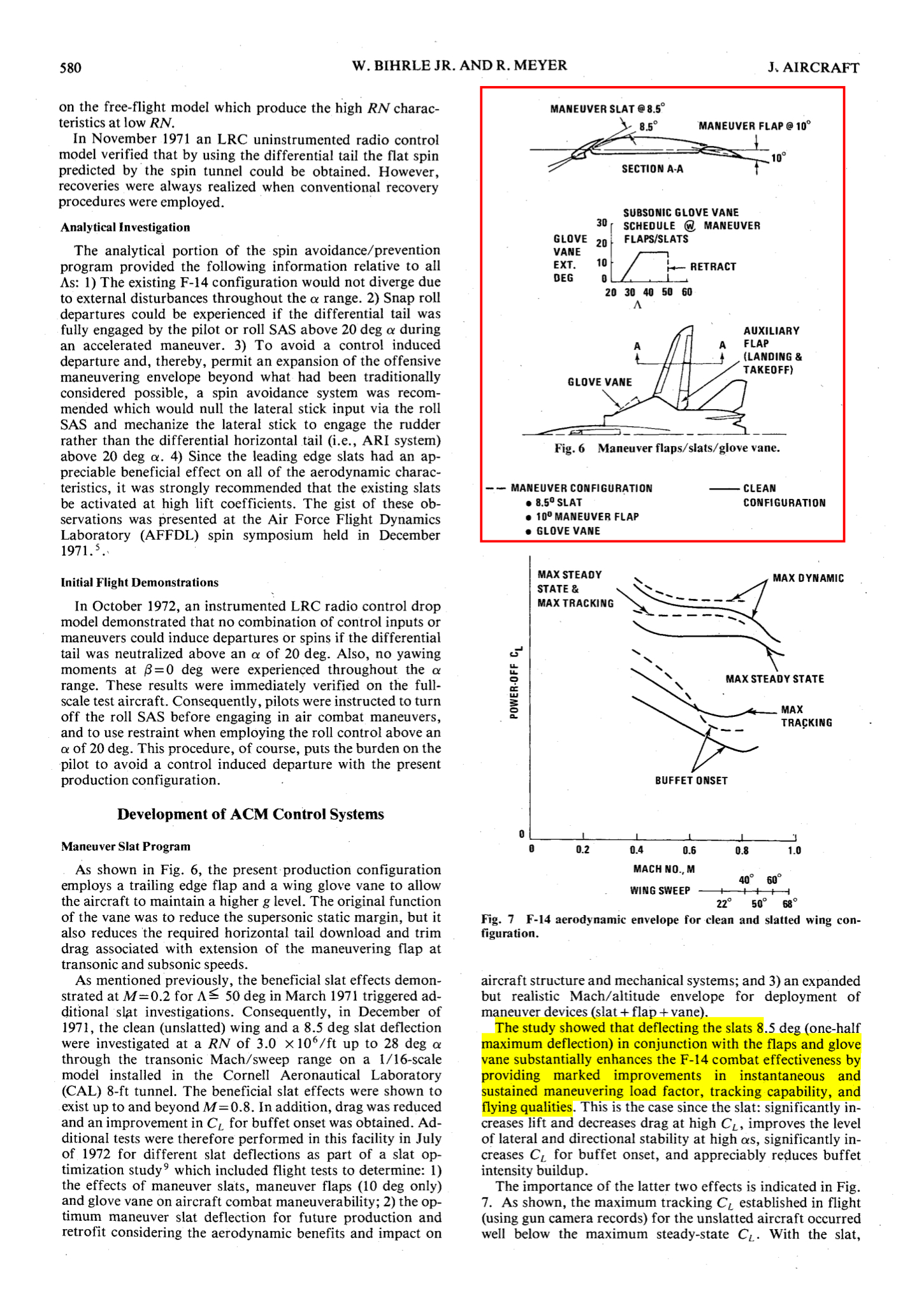
Glove vane normally open above mach 1.4 but can be override open above mach 1.0 iirc. Also, some paper suggested that glove vane can be use in conjunction with a maneuver flap schedule and wing sweep position. By combining slat, maneuver flap, and glove vane, it could improve the handling and the buffet magnitude. However, from what i remember, I cant find the detail of glove vane extension schedule with maneuver flap in NATOPS and thus maybe didn't make it to the operation fleet for some reason.