Naquaii
-
Posts
1141 -
Joined
-
Last visited
-
Days Won
2
Content Type
Profiles
Forums
Events
Everything posted by Naquaii
-

auto muting and setting a radio as priority over others
Naquaii replied to red23's topic in DCS: F-14A & B
A tip with SRS is that you can set each radio to either left or right ear. Fully or partially higher volume. That helps me a lot to have them in different ears. -
Likely because it was a really early HUD and that it was too difficult to make a pitch ladder that was correct to the outside world. Or they just didn't prioritize it due to not having enough experience with HUD interfaces in general.
-
Yeah, there is other symbology like that one and the targeting stuff that is positioned correctly vs the outside world but the pitch ladder is not.
-
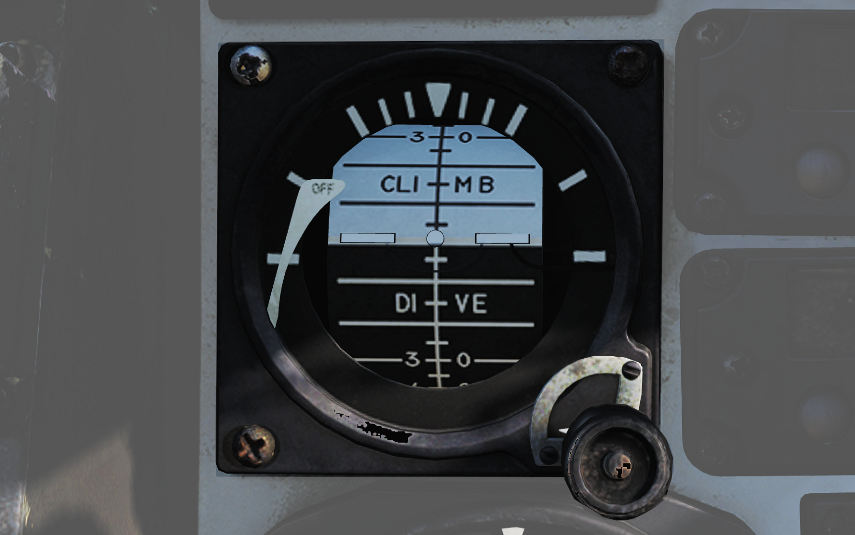
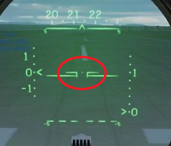
Not sure what you mean by aligned, like I mentioned the pitch ladder on the HUD was never intended to be referenced to the outside world. You can use the trim to move it on the HUD but as it doesn't correspond to the outside world it won't be correct for anything but that specific altitude and aircraft position. You really should regard it as a digital ADI that's on the HUD, nothing more. Imagine the ADI in the attached image transposed digitally on the HUD, that's basically what it is. And the only reference to read the pitch line being the aircraft wings that I've circled in the HUD image. The pitch lines aren't designed to be used as a reference for anything but those. You're ofc free to use it as you wish but this is the reason it isn't detailed in the manual, it was never intended to be used in any other way. This is the primary reason why the HUD in the F-14 isn't a primary flight instrument unlike in newer aircraft where the horizon line on the HUD is in the correct spot on the HUD vs the outside world. (And the other pitch lines for that matter which it isn't in the F-14.)

-
That's because there isn't a setup or trim for "proper use". The pitch ladder on the F-14 HUD isn't at all referenced to the outside world, it just references the wings on the HUD. You should regard it as an ADI on the HUD and an instrument in itself not referenced to the outside world.
-
I disagree, I've yet to see any source of that that's not an internet source without any references or second hand knowledge from some interview somewhere. That's just not good enough in my book to be proof of this.
-
The real problem is that in addition to that we don't even know if they actually worked. As in being able to be launched and having it actually track and hit something.
-
Afaik it's an ongoing thing.
-
Not sure who you've been discussing that with. I've seen exactly no-one defending the missiles going backwards. What we've said each and every time is that the missile kinematics, i.e. the motor performance and the aerodynamics are really close. The guidance however is lacking which makes the missile worse off than it should be due to that, but that also not really something a 3rd party can fix. The issue with the backwards lofting/firing missiles is due to how lofting in DCS works (at least with older missiles) and the fact that players have started to manually loft which wasn't really intended either in DCS or IRL. But no-one is defending that and it's not correct behavior, but again, also not something HB can fix on our own.
-
Known and on the list to be added.
- 1 reply
-
- 3
-

-

-
It's not just that either but these old phosphor based screens are really hard to capture accurately in themselves as well.
-
It's notoriously hard to capture how an old phosphor screen like that looks on video and this is added to that also a kinda crappy old video that has been digitised. The colors are likely way off. My guess is that the AJSH radar looked kinda similar to the PS-37 but that that video is not a good representation of the colors at all.
-
F-14 v2.8 - Jamming, JESTER, and Headless Bodies!
Naquaii replied to Cobra847's topic in DCS: F-14A & B
No, those does not contain the parts related to the weapon systems. Like I said we've had to piece this stuff together from other sources. -
F-14 v2.8 - Jamming, JESTER, and Headless Bodies!
Naquaii replied to Cobra847's topic in DCS: F-14A & B
We have extensive documentation gathered while researching the aircraft. Stuff like maintenance manuals etc that while unclass isn't available on the net. -
F-14 v2.8 - Jamming, JESTER, and Headless Bodies!
Naquaii replied to Cobra847's topic in DCS: F-14A & B
It's purely trigonometry, the only thing the radar knows is the angle to target so, like I said, you need to have either a previous track which gave you altitude and speed or the RIO needs to guess. -
F-14 v2.8 - Jamming, JESTER, and Headless Bodies!
Naquaii replied to Cobra847's topic in DCS: F-14A & B
We can't really tell exactly how the AIM-54 was launched simply from this and how the AWG-9 was affected. There's not really any information about this in this document, just that it could launch at it and hit it. The ADR used angle to track and speed and altitude to estimate range, but was hard to use as you'd either need good previous measurements from the radar or good guesses from the RIO and would become increasingly inaccurate as soon as the target manuevers. You also need quite a bit of altitude difference for it to work at all. And just to be clear, this is currently not modelled in DCS. -
No, you're misinterpreting it, the only release date given is still winter 23/24. (Until end of March) As my attempt at a clarfication tries to say is that what Cobra meant is that the team is busy finishing off certain features to show those features off. He's not talking about the module in it's entirety. You can't just read "this week" and skip all the rest!
- 29 replies
-
- 17
-
-
-
It should be positioned in the right spot according to seen closure but you also have the closure rate on the other side so there's really no reason to use that. The point of it existing is that it's the actual radar return and that you want to see that visually, the other readouts are better for basically everything else in STT. The part about the azimuth is that the radar doesn't adjust for seen groundspeed (ownspeed) at each azimuth, it just applies own speed across it all. That's why the MLC is a curve, not a line. So with greater azimuth you have to compensate for that curvature yourself as you should really measure distance to the MLC curve, not to a straight line across the scope. In this case my guess is that the deflected real return in code is using that position to display the return, not what it would be at the actual azimuth. Unfortunately I don't really have the time and ability to load those files in atm and have a look so if there's anyone else here that feels like helping that'd probably be quicker.
-
I've been able to reproduce but the first issue is likely not a bug, if you switch between the different aspect settings the previous location remains for a moment before being erased, that's just how a screen like this works, like an after image. So unless those extra markers remain over time that's not a bug, that's just how the screen works. The other one is a bug though but a minor one as far as I can see.
-
Seems like you've actually stumbled upon two unknown bugs here (at least to me). The extra markers seem to be the target returns from the two other aspects which shouldn't be there and the positioning of the target rate vertically seems to take azimuth into consideration when it shouldn't. (Normally you have to consider the location for the MLC for targets offset in side for azimuth). So both of these seems to be bugs and I'll save your screenshots and report them. At least it shouldn't hinder anyone as you're better off using the closure rate on the right anyway. So please disregard the location of the target return on the left side in PD-STT for now.
-
Both STT modes build a trackfile that drives the target tracking, the difference is just how it calculates the different values. In P-STT it tracks using angles and range but that is then used to calculate rate as well so the rate shown is valid. In PD-STT the target is tracked using angles and rate and the range is then measured using FM-ranging, kinda how it is in RWS and TWS. To be able to show range vs azumith in PD-STT the AWG-9 shifts the real target return to the left and generates a synthethic target return at correct azimuth and range instead. It's a bit hard though to say too much about the scenario you describe other than that it can be hard to get the radar pointing exactly where you want it too. An IRL RIO would likely use a 1bar or 2bar scan and try to point it straight at the target instead but that can take much training. Also the range of the pulse modes is much less than the PD modes. Also remember that the altitude coverage indication is for coverage at the selected TID range and only shows coverage at TID cursor when you're in half-action.
-
No worries, it's very likely something that could be expanded upon in the manual. Truth to be told there was a time when it had us confused about it as well.
-
When coming from pulse search it's range and and when starting in a PD mode it's rate. The only time you get range on the DDD in a PD mode is in PD-STT. But both STT modes show range and the current range scale should be indicated on the readout above the screen.
-
Yeah, that part about the Vc switch is a lingering error. What the aspect switch does is that it selects which parts of the doppler filters that are used in the pulse doppler search modes, so not just PD Search but RWS and TWS as well. In beam the screen covers from -1200 to +1200. In tail it's +600 to -1800 and in nose it's +1800 to -600. So the middle cross is 0 in beam, -600 in tail and +600 in nose. And yes, opening is towards the bottom and closing towards the top. The actual scale marking numbers shown on some DDDs became defunct quite early on and should be disregarded.
-
I'm not really sure what to tell you, what you're saying doesn't make sense. What you're describing for Tail and Beam seems about right but slightly above the cross in Nose would be more than 600 knots closing. But neither of this makes sense if it's the same target, his velocity would of course not change because of the Aspect switch, that's something I've never seen. That's not something I can explain from the information you've given me. As for the Vc switch, that's correct, the Vc switch only sets the scale on the DDD for the Vc indicator in the STT modes. It doesn't do anything in search.