m0jo
-
Posts
120 -
Joined
-
Last visited
Content Type
Profiles
Forums
Events
Everything posted by m0jo
-
Not seeing an upgrade option even with ownership of Black Shark 2
m0jo replied to elmo's topic in DCS: Ka-50 Black Shark 3
If you bought BS1 in ~2008 and upgraded to BS2 a while ago, you can merge the BS1+BS2 into a proper BS2 license and then the discount to BS3 will show up. There is a menu in the bottom left of the license page to convert a BS1+BS2 upgrade to BS2. https://www.digitalcombatsimulator.com/en/personal/licensing/ -
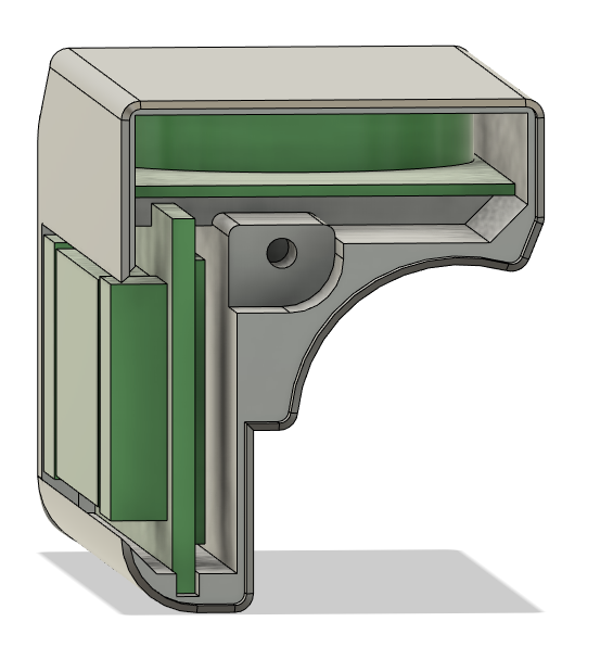
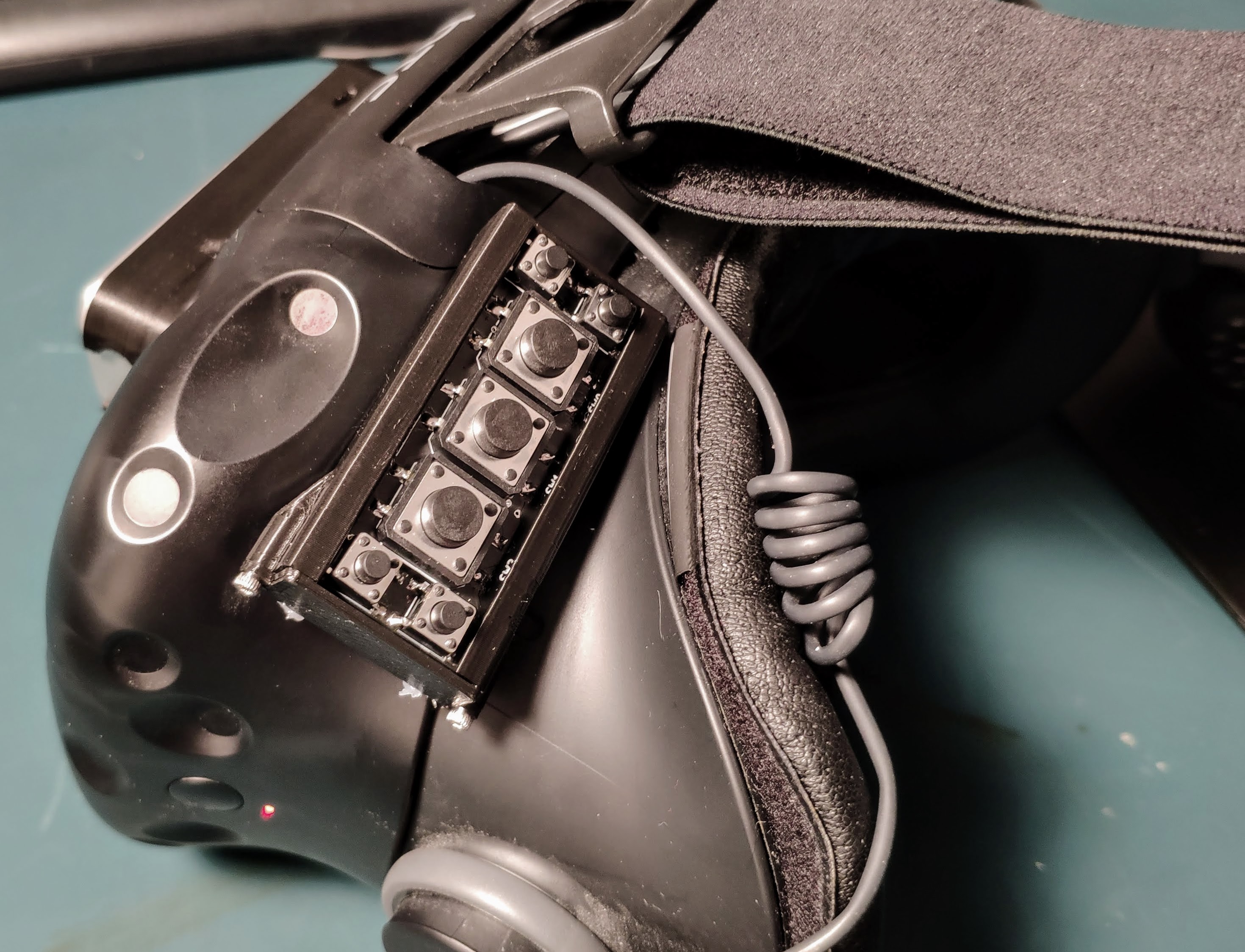
The electronic is based on the design of the Redox Wireless mechanical keyboard. The firmware was modified to support the keyboard, and 4 others devices with up to 7 buttons each on the same USB receiver. The receiver is exactly the same hardware, the custom PCBs are pretty much only connecting YJ-14015 boards with NRF51822 microcontroller to the buttons. The receiver is using a Arduino Pro running QMK to handle all the USB HID devices. Here is the 3d model with the endcap removed (easier to see details than with a photo with the black plastic). The CR2032 battery+holder is on top on a thin PCB and the NRF51822 board is on the back of the PCB holding the buttons. Only 2 wires are used to connect the battery PCB to the main PCB. Almost the same design is used for the buttons on the headset, but the battery is on the same PCB, and the thickness of the CR2032 make the entire thing a bit too thick to be finger mounted. Here is the backside of the assembled PCB on the headset (buttons are on the other side): The design in the previous post is actually the 2nd version, here is the original version with the battery in the back:

-
Hi, here is my take on it. Instead of Bluetooth, this is using Nordic Gazell protocol with a small dedicated receiver running QMK. Only the receiver need to be flashed (via USB) if some key mapping need to be changed. This support keyboard buttons, mouse click, mouse wheel (with acceleration) and joystick buttons press. The CR2032 hidden on the top of the finger should last a few years since the microcontroller is always sleeping and don't need to stay in sync with the receiver. There is no delay after pressing a key, this is very similar to pre-Bluetooth wireless keyboard/mouse. I also added some extra wireless buttons on the VR headset with the same design (but different PCB) for things like centering the view and catapult salute
-
Open Source Joystick FFB / DIY FFB Joystick
m0jo replied to Berniyh's topic in PC Hardware and Related Software
For the pedals I was only thinking of faking the ffb and make assumption based on the commands received to the XY axis and send similar force command to the pedals. From what I read and remember DCS does not support 2 FFB devices, so only the stick will be properly detected as a FFB device, and I will simply add another axis on the USB controller to send the positions of the pedals. This is mostly for force-trim on a helicopter, so when the XY axis will receive a different spring center command, I will also change the spring center on the pedals. Either that or I will intercept the trim button press on the stick and will change the spring center of the pedals that way. -
Open Source Joystick FFB / DIY FFB Joystick
m0jo replied to Berniyh's topic in PC Hardware and Related Software
The motors are not used as counterweight, one of the axis is sitting level because the motor is in-axis with the gimbal, while the other axis is tilted in the picture because the weight of the motor is pulling on one side. This is intended to be a floor mounted joystick with the rotation point somewhere halfway between the seat and the floor. There will be a counterweight under pivot point to balance the grip and to keep it neutral on all axis. I was intending this as mostly a helicopter force-trim, but I think I can simulate control loading by moving the motor depending of the axis position. Im currently using a overkill STM32L476RG (about 9$), I could use a cheaper micro controller but this kind of optimization is not worth it a the low production count sim equipment have (and I might only produce my stick... ). The controller is detected as a FFB stick and I can receive the command that DCS send to the stick. That code was done about 1 or 2 years ago so im a bit fuzzy on the details. There are 2 hall sensor per axis, one of them is used to send the data to the computer without any backlash. The other sensor is used to read the position of the offset created by the motor, the difference between the 2 measure will be used to control the offset created when the cyclic is trimmed. I also intent to link a set of FFB pedals with the same controller, this will enable force-trim on the pedal when the stick receive the trim command. The board also have connections to read and send the button press of a Thrustmaster Warthog, I intend to intercept theses button press to be able to set a force-trim in simulator that does not support FFB. -
Open Source Joystick FFB / DIY FFB Joystick
m0jo replied to Berniyh's topic in PC Hardware and Related Software
Im currently building a prototype based on ¨indirect¨ force feedback with worm gear motors. I had also done 2 others prototypes with a direct gear motor and a cam based centering. This is the 3rd and current prototype without any cams, the centering force feel fine, it look like some mods done for the Thrustmaster Cougar. Everything pivot point are on ball bearing and digital (i2c) Hall effect sensor will be used, so even without the functional FFB the feeling should be great. To simulate different force, I was thinking of using the motor in a more dynamic way like following the stick to reduce the spring force instead of simply offsetting them from 0 like a helicopter force trim. The new PCB design is almost finished and the boards for the new Hall effect sensor are ordered, I should be able to have something working in a month or two if everything go wells. The source code of the FFB stick is also mostly done to be able to check the functionality, it even have a CLI interface:megalol: (the first prototype firmware will still need some fix) The first prototype with direct geared motor was probably too strong. The force and feeling when pushing against theses brushed and geared motors was not great, the coggig of the motor was quite bothersome. The force was strong enough to be able to lift a Thrustmaster Warthog from horizontal with about a foot long extension. The second prototype with cam based centering had a loose center, the shape I used for the cam was probably wrong and the springs I had were too weak. An album with the other prototypes pictures: https://imgur.com/a/5bji6 -
Is there any interest for an i/o system??
m0jo replied to Gremlin77's topic in PC Hardware and Related Software
Cable/pins/track capacitance will limit the number of slave and cable length on a I²C bus. The maximum capacitance on the bus should be around ~400pF, every pins add about ~10pF and each meter of a CAT5 twisted pair will add ~52pF of capacitance. External interference like PWM dimming might cause problems on the I²C bus. You can check the PHCC project before re-inventing the wheel, this board support a lot of different input and output. The hardware on these board also support I²C but this bus isnt supported by the current firmware. I was working earlier to add this missing function to the firmware but never actually finish it / debugged it. I'm currently working on a python interface between PHCC and DCS:World. At the moment, buttons, leds and analog inputs are tested in my pits and working correctly. Other output like servo, analog output and stepper motor should also work without majors problems. I didn't create a GUI for my python scripts and some of the python modules used are kind of messy to install correctly, so my projects isn't aimed at beginner at the moment. -
Thank you AceKng and PeterP, It seem only step #3 is needed, everything is now working normally.
-
I have joined a few logs files and the dxdiag.txt file. Im pretty sure this bug is caused by a combination of SoftTH and the new alt-tab bug. Logs.zip
-
This problem is now solved, to correct this problem, set keepComposition=1 in the [main] section of the config.SoftTHconfig file. If you keep having problems, try the others steps in this quote taken from user AceKng1 in this post: I'm having a problem with DCS World, the game is freezing when I click on either the top third or the left third of the screen. This look similar to the alt-tab bug but the alt-tab command is not working with SoftTH, the game always stay on top. I'm using SoftTH to extend the game to the 2 lower screen, at the moment, only the Abris screen is exported on the lower screen. For example, if I click on the left side, the game freeze and alternate between 2 frames until I click in the other section of the screen. The cursor also change from the yellow cross to the white arrow when its pointing over this part of the screen. When the cursor is in the other section of the screen, I can click on the button normally. Here is a short video about this bug: While filming this bug, I also crash the game to the desktop by simply clicking in the left part of the screen:
-
The new parameter is called "v_angle_shift" and is located in "DCS World/Mods/aircraft/Ka-50/Cockpit/Scripts/config.lua". With this parameter set to 0, the HMS is centered in the screen.
-
Yes, this simple checkbox could solve a lot of problem for simbuilders with custom/non self-centering rudder pedals. The rudder trim command should still be sent to the KA-50 AP but the position of the pedals in the sim should always move with the real pedals. The implementation could be similair to the cyclic with a force-feedback joystick.
-
Yes, it's a Saitek X52 mounted on a Microsoft ForceFeedback 2. The MFFB2 have also been modified with 2 Hall effect sensor. The brake lever is connected to a potentiometer and a return spring underneath. This is an older picture without the brake lever and the force feedback pedals:
-
This is my Ka-50 pit at the moment, im using two 17 inches screen to display the gauges. I didn't draw/cut the button holes and the hole for the panel in the center, below the shkval and the abris, because I didn't draw those panels yet. I have modified the position of the indicator a bit to fit within those 2 screen and the screen do not stickout in the leg space. Those are the dimension I guestimated for my pit:
-
I have uploaded the design files. I have also made a blog post with a bit more information about the modification. I am also working on a Python interface between DCS and the PHCC motherboard. This other project is also almost finished, I only need to test my system a bit more to be sure everything is working correctly.
-
I solved the breakout problem by replacing the IDC connector on the PCB with those connector (277-1800-ND) and a modified PCB design. I have etch those board myself but even a pcb prototyping service could produce these board quite cheaply, IteadStudio can produce 10 of these sized boards for only 25$. The component on the PCB are also quite cheap to purchase, the modified key 64 is only about 9$ in parts. The key64 also have a low price, about 10-15$. Modified 7segment card: Modified key64 card:
-
PHCC support was planned originally for Helios but was abandoned for some reason... Opencockpit is not supported by Helios but it will work with a custom export.lua script.
-
This servo cannot be commanded to a specific location, only the speed can be controlled. A normal servo should be used instead. There is also a lot of cheaper option either the PHCC system or the simpler servo opencockpit card. Phidgets device are really expensive for their capability compare to the PHCC cards.
-
The game use a float value between 0.0 and 1.0, sioc can only use integer. Multiply the value by 100 and round it before sending the data to the sioc server. The data received by the sioc server will then be between 0 and 100, you could also use a factor of 255 instead of 100 to interface directly with some servo.
-
Problem with automatic turn and aotopilot
m0jo replied to ArtMan_NL's topic in DCS: Ka-50 Black Shark
Because its center the nose direction with the target, the missile launch symbology is a bit off-center depending on which wing the missile will be fired from. If the ripple length switch is set to long (2 missile per shot) the reticule will be centered. It could also be caused by a badly trimmed aircraft and wind. -
Mini HDMI -> HDMI will keep the sound and other information in the signal.
-
There is a few things missing in the export.lua that could be implemented in this patch. A function similar to : EKRAN:get_actual_text_frame() -- return UTF8 string with current text of EKRAN screen should be implemented for the screen of the PUI-800 and the screen of the PVI-800. This function could also be used on countermeasure display of the A-10C. This function is quite essential to pit builders because without it, the data on these screen need to be guessed indirectly from the waypoint table and the weapon table. Also, a setting do deactivate the center trimming on the rudder axis would be great for user with either force-feedback pedals or non-self centering pedals. Without this setting, the self centering is a PITA with those type of rudder.
-
Connect the 3 terminal because the BU0836 is measuring the voltage at the middle of a voltage divider created by the pot. The two external connector need to be wired to +5v and GND respectively, the middle connector (the wiper) need to be connected to the analog input. The old pot wiring of the Suncom was by a joystick port/soundcard and these measured the resistance between one external terminal and the middle terminal.
-
ED seem to be using a ejabberd server for authentication with a TLS encryption. The server address is master.eagle.ru:5222. The list of server IPs are probably sent over the jabber connection. After receiving somehow the server list, the client is opening a UDP connection to the different game servers with "getinfo"+ something I don't recognise as data (maybe time or a checksum). The client then receive a response containing the briefing in text and some other data(probably something like player number in hex) If you want more info, use ireshark to sniff the connection between your computer and the different server.
-
Use another piece of wood as a guide for the jigsaw. With this, the edge are pretty straight if you follow the guide correctly. Also a jigsaw is ideal to cut acrylic if used with a blade with small tooth (normally to cut metal)