nairb121
-
Posts
57 -
Joined
-
Last visited
1 Follower
-
There's a mic switch on the throttle which should be used for this.
-
Gun reticle accuracy and seat height [user problem]
nairb121 replied to Rifter's topic in DCS: F-5E Tiger II
Isn't the reticle collimated, projected to infinity? Unless there's an issue with how that's simulated, seat position should have no effect on the reticle's alignment. -
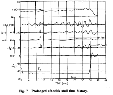
The F-5E in DCS, when clean, has an angle of attack at full aft stick of approximately 21° when gun ammunition is loaded, and approximately 25° when the guns are empty. Based on the public sources I've found, these are too low; capability should be approximately 30° (presumably with guns empty). The paper here https://arc.aiaa.org/doi/10.2514/3.45660 concerns the departure characteristics of the F-5E and the means by which an impending departure could be detected and the pilot warned. This section (found at the top of the second page) states that pitch acceleration follows stick position up to about 30 degrees, at which point further pitch up is prevented by the aircraft's aerodynamic stability. Fig. 7 also supports this - it shows time history of various flight parameters during an extended full-aft stick stall. The angle of attack can be seen as approximately 30 degrees for the majority of the time, further increasing to 40 degrees at the onset of post-stall gyration. (It should also be noted that the DCS F-5E shows little tendency toward PSG in this regime) An additional source for the F-5E's AOA capabilities is this NASA report regarding the development of the "shark nose" used in the F-5E and F-5F. https://ntrs.nasa.gov/api/citations/19790001876/downloads/19790001876.pdf . This report mostly concerns the F-5F, but also includes some F-5E data. Figure 6 shows flight data for 1g power-off stalls for the F-5E - the charts are more difficult to read, but they do show similar AOA tendencies of 30 degrees at full aft stick, and up to 40 degrees upon departure. I've attached a track in DCS attempting to replicate these tests by performing an extended wings-level 1g stall with guns unloaded. Upon full application of aft stick, the AOA remains between 25-26°, never approaching 30. F-5 1g stall test.trk Edit: I didn't realize the first document linked was incomplete; a full version is attached. F-5E_Depature_Warning_System2.pdf

-
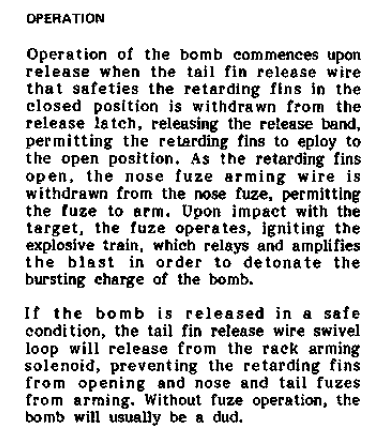
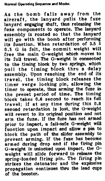
Mk82 Snakeeye deploy in Highdrag when in Nose Fuse
nairb121 replied to Stryker990's topic in Bugs and Problems
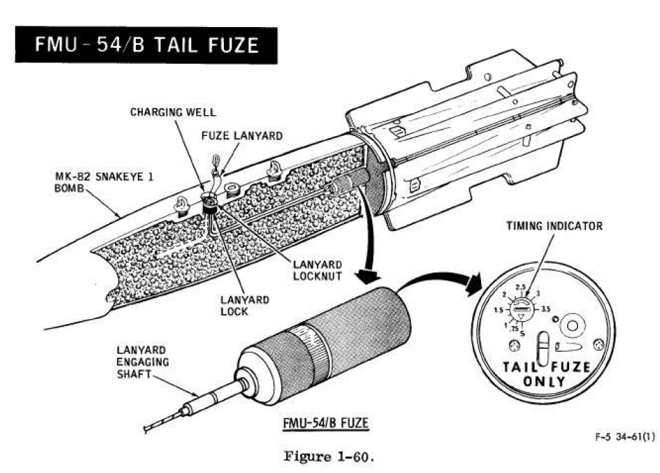
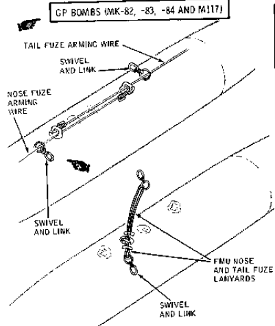
I found a few relevant sections in the F-5E-34 manual (accessible at https://www.digitalcombatsimulator.com/en/files/1946809/) : From page 1-89, in the section relating to the Snakeye: From pages 1-119 and -120, in the section on the FMU-54/B tail fuze used in the Snakeye: And page 1-134, showing arming wire/lanyard installation for the Mk-82 Snakeye: There only seems to be one swivel and link, rather than two as used on typical GP bombs. If I'm understanding the diagrams and descriptions correctly, the swivel and link (if the station is armed) pulls the fin release wire, causing the fins to open. The tail fuze, if present, is linked to this wire and is also pulled. The nose arming wire is linked to the fins, and pulled out by their opening action. This is supported by the first excerpt, "As the retarding fins open, the noze fuze arming wire is withdrawn from the nose fuze". However, it seems like it would be possible to have an additional swivel and link connected to the nose fuze arming wire, which would be connected to the nose fuze arming solenoid. The manual makes no mention of this for the Snakeye, though it's similar to the arrangement used on GP bombs. It would have the effect mentioned though - if this was pulled, but not the swivel and link connected to the fin release wire, this would arm the nose fuze but not release the fins or arm the tail fuze. Maybe this is the setup used on the other Snakeye-equipped modules?
-
A g-load that high can't be sustained for long, but the pilot should still last at least 2-3 seconds (and that's all this maneuver was). There's an IRL case of an F-15(C I think) pulling 13-14g in an emergency dive recovery. IIRC they were able to RTB safely, but the plane's structure was permanently bent, so it was written off.
-
The thing is, the wings don't break because of a specific g-value - they break because they are carrying a force greater than the structure can withstand. The same g with a lighter jet is a lower force (F=ma), so a lighter aircraft can pull more g at the same wing stress. This is what the 1.5 design safety factor is applied to. This is also part of why a clean, light jet typically has higher allowable g-loads (like in my manual excerpt above) than a loaded, heavy one (the main other reason being store carriage limits). If another aircraft in DCS always breaks at the same g regardless of weight - then that is a modeling inaccuracy on that aircraft and shouldn't reflect on the F-5.
-
It's not impossible, but it would surprise me if this were the case on an older module like the F-5. Also, the original screenshot at the top was taken after several minutes of flying with high g-loads (though I don't know the exact numbers reached) - if that's why it broke at 13g after 2 hard pulls, then it probably would've broken far sooner in the original scenario.
-
My thoughts as well - I recorded a short track at 10% fuel and 50% ammo. First pull is to 13.1g, second is to 14.0. Third pull to structural failure - interestingly, this occurred at 13g - maybe I introduced some roll inadvertently. F-5 14g.trk
-
It's neither, just a very hard (but, importantly, smooth and symmetrical) pull at very low weight. The tolerance of the wings is very sensitive to aircraft weight, and the aircraft was clean and, as this point, probably below 1000 lb fuel. Refer to my post above - given the ultimate strength implied by the prescribed g-limits at the maximum applicable weight, at very low weights the aircraft should be able to survive over 14g.
-
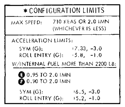
From the manual, for no stores except wingtip - limits are 6.5g above 2200 lb internal fuel (about 45%, gross weight roughly 12,900 lb) and 7.33 g below 2200 lb internal. Full gross weight is around 15,600 lb (all weights including full ammo). 6.5g at 15,600 lb = 101,400 lb "effective" weight supported by the wings; 7.33g at 12,900 lb = 94557 lb. Taking 101,400 as the "rated maximum" weight, and using a 1.5 safety factor, that gives a failure force on the wings of 152,100 lb. If I'm running on fumes and out of ammo (at empty weight of 10,308 lb), that means I can pull 14.8 g at the same wing strength. (Full discosure - I was not aware before that g was limited to 6.5 above 2200 lb internal fuel.)
-
The structural failure point is highly dependent on stores and fuel weight - clean and at 60% internal the wings fail at around 12g, and near fuel exhaustion it can get to around 14. Rapid G onset might cause it to fail earlier though. (Also I think that's me in the screenshot, hi!)
-
-
The critical factor in this testing was the fixed position of the stabilators. As you said, the aft CG results in less tail downforce required in level flight at a given speed; however, with the tailplanes maintained in their position, an aft CG results in a nose-up moment for this reason, with the result of stabilizing at a higher AOA and lower speed. With the stabilator position removed as a variable, and in steady state, the pitch moment equation becomes a relation only of AOA/speed and CG position. However, this is the reason that I'm seeking to perform further, and more straightforward, testing to confirm before submitting a bug report. My intent is to test this based on rotation speed with neutral stick; V^2 will be proportional to Weight * CG distance forward of the wheels.
-
I was just referring to the way the CG/AOA trend toward the far right side of their respective graphs. And I am indeed comparing, or at least relating, the %MAC and the AOA graphs - the AOA in stabilized level flight at a given stabilator angle is purely a function of the CG location. Correct, it's just a tank that feeds by gravity alone into the aft tank. My only concern with it is its effect on the CG. Unfortunately the manual refers to other documentation for CG calculations, which I have not been able to find. This would be much easier if I could. My purpose in this is to confirm whether the modeling is correct, and provide solid evidence for a bug report if it's not. It's relevant because, if my hypothesis is correct and the tanks aren't being used in the right proportions, it causes the CG to be up to 3% MAC aft of where it should be, causing incorrect flight behavior.
-
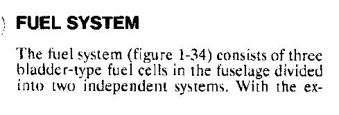
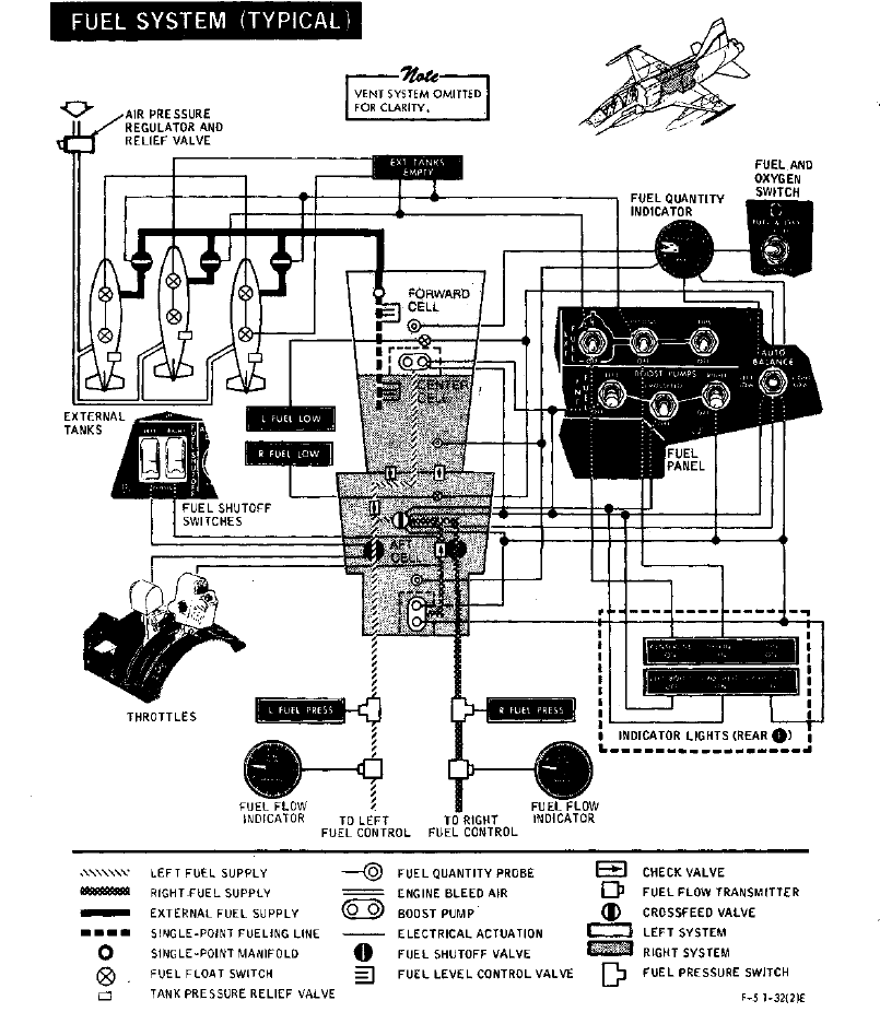
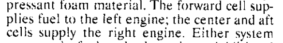
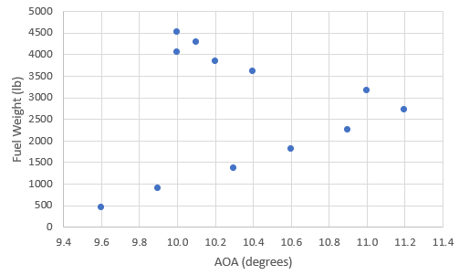
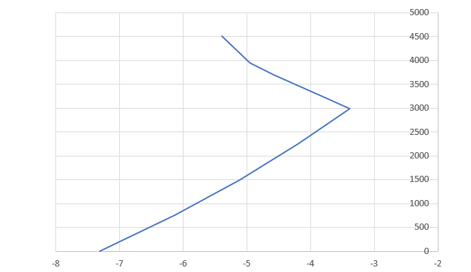
The center cell is mentioned on 1-41 and shown in the figure 1-34 on page 1-42: Using the known system capacities and the CG travel (in the previous post), I was able to determine approximate values for the tank positions and capacities, and produce a plot to confirm these value match the manual: My previous testing was based on determining AOA for straight and level flight at the same stick position for various fuel states (set via mission editor and with unlimited fuel) - a tail-heavy aircraft would hold a higher AOA and lower airspeed, and a nose-heavy aircraft the opposite. In theory the graph of AOA vs. fuel state should follow the same trend as the CG shift shown above - but the trend was quite clearly different: It offsets to the right similarly to the unbalanced trend; however, the fuel was not unbalanced (since it was unlimited and set by the editor, it couldn't be), and the point of the farthest aft CG was at a much higher fuel state. However, after some trial and error I discovered that it matches closely the plot of the CG if the center cell depletes completely before any consumption from the aft cell (the CG is significantly forward of the previous plot as the tests included ammunition): My plan for followup testing this weekend is to do some takeoff roll tests - with neutral stick, the speed at rotation will be a function of the CG and the total weight of the aircraft.