hawxxer
-
Posts
5 -
Joined
-
Last visited
-
Do you start the game with DCS Updater Utility? Try start the game directly with the dcs_update.exe. Worked for me.
-
Question to owner of the Virpil Throttle
hawxxer replied to -Relax-'s topic in PC Hardware and Related Software
I have this issue with cm as well as cm3, maybe increasing filtering in virpil settings can fix this -
Interested in the throttle, I sent you a pm.
-
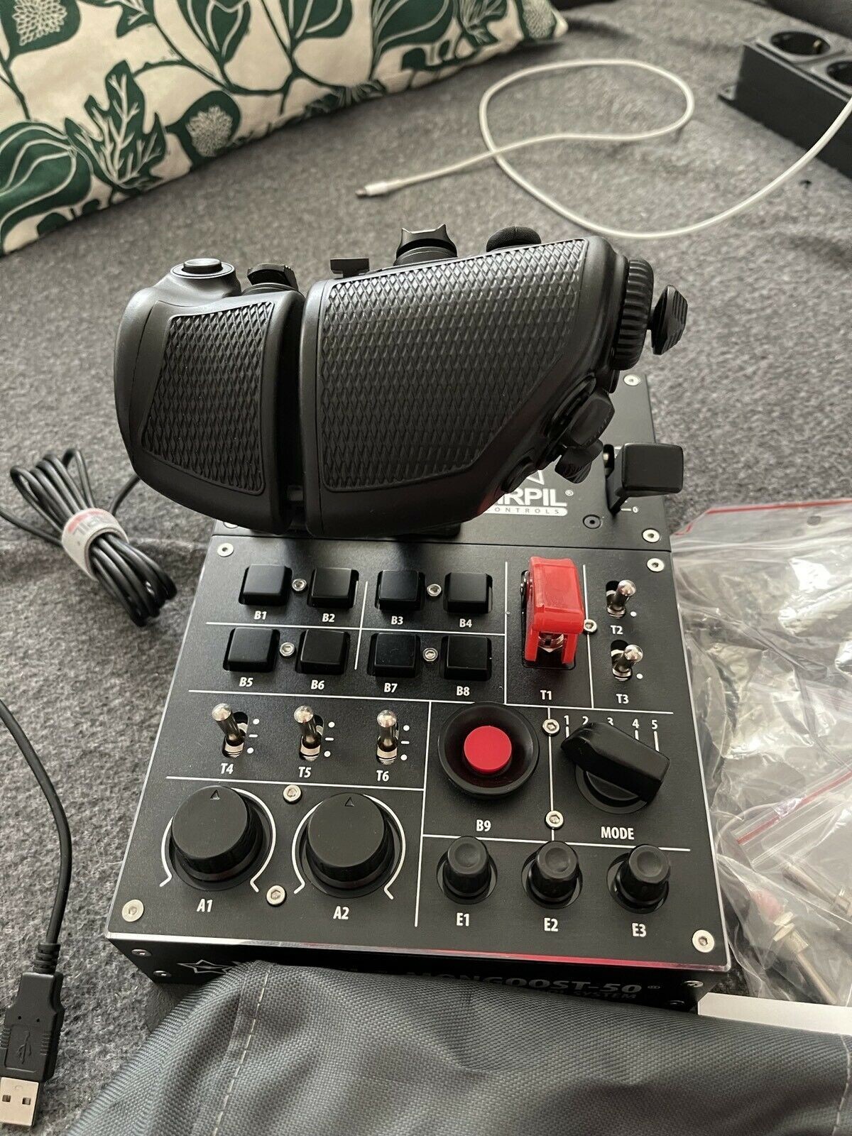
Hello, I want to trade my VPC MongoosT-50CM throttle for the newer CM3 version. If someone is interessted in that, just hit me up.

-
Hi guys, I am currently adapt my Cougar throttle (stick is not existing) to USB. Someone got the schematic for the Cougar Throttle? My research lead to the post of Uriba but it does not look like this is the correct schematic for me. As you can see from his schematic, he has resistors in it, my PCB only has diode on it, also measuring the resistance does not work out like his schematic. My PCB looks like this one. But there is another one with more components as it seems? (Did not find a higher resolution, but you can clearly see components in the middle near the big connector) Does someone have the pinout for my Version, or do I missing something? Also I am not sure about the big connector. The connector coming from the handle has 12 rows, while the connector on the PCB only has 11 rows. which side of the connector is not connected? On the picture I linked above (first one), it looks like the missing connection is on the right side but I would say it needs to be on the left side, as the crimb of the cable goes from right to left and the left side is missing two cable positions.