Bear21
-
Posts
97 -
Joined
-
Last visited
Content Type
Profiles
Forums
Events
Everything posted by Bear21
-
reported FCR A-A SAM steals FCR range from pilot
Bear21 replied to Bear21's topic in Bugs and Problems
The DCS F-16 Early Access User Guide page 238 "Dual Target Track (DTT). Dual Target Track is entered from SAM by bugging a second target.", which is what I did. No effect. Regarding the range hijack, I never flew the F-16C so can't say but it seems to me the programmer took the easy way of using the STT behavior for SAM and DTT. For Single Target Track (STT) the FCR control of display range makes sense, but for SAM not, as SAM shall allow stepping up to DTT, which can be at a different range to the SAM target. The solution is to do nothing for SAM and DTT, let the pilot manipulate range. -
reported FCR A-A SAM steals FCR range from pilot
Bear21 replied to Bear21's topic in Bugs and Problems
Here is the mission file for others to try. Mission: Kill off the Mig29s, then the Tu95. Observe how the FCR controls range scale from SAM (one TMS up) start. F-16 2 Mig29 CAP R27, R73 and Tu95MS, E3 Caucasus.miz -
1. The appended track shows how after entering A-A SAM the FCR steps down display range on its own both before and after AIM-120 launch (18:53:30 and fwd), and does not allow the pilot to increase display range to control second Mig29 (several attempts to increase range to control second Mig29 are not accepted). 2. The FCR does not allow DTT on said Mig29 when it's within the hijacked range, instead it continues to step down range as SAM (on Tgt 1) comes closer and is active (there is no need for the pilot to have the SAM target at an optimal range display, you only need to watch azimuth coverage for datalink updates to AIM-120). In cases where the second Mig29 is further behind you are victim to the FRC and can't follow Mig29 no 2, even though you are in SAM and not in STT or TWS. 2024.1.4 F-16 vs 2 Mig29.trk
-
Radar Target aging sets target aging and not track algorithm timeout
Bear21 replied to Bear21's topic in Bugs and Problems
Finally, thanks for the info. -
I've read the radar whitepapers you have published. Seems ED has now got a competent radar specialist and that the APG-73 and -66 are heading in the right direction. It would then be nice to have confirmed that the Data/Target aging setting then sets the DISPLAY target aging and not the target tracking algorithm timeout (as continuously claimed to be the correct way by ED, as the Pilot shall set the tracking timeout and not the RDR!). The radar tracking algorithm, running in the RDR admin computer, configures the track scans and its timeouts as it sets all detection parameters through waveform, PRFs, scan patterns etc., and thus has all the info about revisit times and how to configure timeouts after " n " missing paintings. This shall be done automatically by the RDR; pls confirm this is or will be the case!
-
Just want to give a heads up. I have Virpil stick, throttle, and pedals and have used a software version from 2020. It has worked fine, but I noticed since ED reworked controls that the dialog, in game especially, was laggy. When I recently bought the Varjo Aero and started using VR again, it was so laggy it was not useable. Turned out the culprit was old Virpil software; updated, and imported profiles, and now everything works fine. Just for info.
-
I've used Updater 1 to build one click DCS launch with 2D/TrackIR or alternatively VR, including all the different settings. Working with 2.0 it's not clear how to achieve similar simplicity. Are ALL the pre-launch actions, including pre-launch apps (SteamVR, Varjo base,...), ST or MT, launch APIs, scripts etc, + the Graphics presets, collected in Presets (You have #1 to #4)? Or how do you achieve such a batch action? I fail to find any description of the base principle of 2.0 (I've watched the Utube video which shows the features but it's not clear how these are related and connected). Any link that clears this?
-
Moderator, delete topic. Sorry/Bear21
-
There is a good document describing the history of French radar development (appended), that also describes the Cyrano IV. It's a non coherent Magnetron radar that CSF tried to make reject main lobe clutter with a clutter coherent MTI block filter. It didn't work (as per the document) as the antenna used in the Cyrano IV, the inverted Cassegrain has rather high sidelobes. Clutter comes in at all relative speeds through the sidelobes and therefore lands in the echo space outside the MTI suppression. Your faint aircraft echo is now competing with ground echos. The Russians had the same antenna type (it has many advantages, no Waveguide flexible joins, agile twist plate, but at the expense of sidelobes) and transmitter in late Mig-23s, tried the same type of MTI suppression and had the same problems. For lookdown you either need HPRF and a doppler filter bank (your clutter doppler frequency is outside the echo range) or MPRF, a multi-PRF scheme (to eliminate blind spots), a doppler filter bank and an antenna with very low sidelobes. French radar history.pdf
-
reported F-18 radar has wrong RWS scan centering mode
Bear21 replied to Bear21's topic in Bugs and Problems
This bug was reported on 17 April, was first labeled "Correct as is", then after my plea to BIGNEWBY changed to "Reported". But nothing has happened. We are now two months later and three releases, and no change. This is a BIG bug, the F-18 radar is the only contemporary radar in DCS that can't offset its can center in search (RWS), it can only scan straight ahead (except for using Spotlight which is not the same thing). Please: 1. Change the present RWS miniScan (which is a lock-on procedure and indeed results in an STT) to follow a double TDC depress. 2. Implement the RWS single TDC press outside a brick/track to change the scan center like in TWS (which has the correct modes). The text and discussions in the original thread is correct as is the provided track, no need to provide a new one. Everything is still the same since April. -
Yes, if the processing gain of the pulse compression is one to one with a shorter pulse with a higher peak power. This is my point, you can rank radars from the same time period using average power and antenna gain, given you understand how they operate (HPD + MPD or not, dual mode transmitters or not, pulse compression or not, receiver technology and processing, scan time on target, etc.). I would be careful saying you can predict their actual range as this requires detailed knowledge of the radars but also of the targets characteristics (a simple RCS value is a huge simplification of a real A-A target).
-
Nice try LaFleur , but you can't calculate anything meaningful with this calculator. It's made for old style pulse radars as it ignores pulse compression gain and integration. Further, you need the peak power derived through a reasonable duty factor for the mode you are modeling and read up on what dB is. I'm not trying to be difficult but the absolute range calculation of PD radars need detailed knowledge of a number of rather tricky parameters. This is why I stay with the relationship of the range between the radars, which is much simpler to estimate.
-
The APG-73 and 68 are Pulse Doppler (PD) radar with multimode transmitters and use pulsecompression to run the radar to their transmitter limits in the different A-A modes. With assumption of the same bracket for receiver noise factor, integrated pulses and compression processing gain, the differences in range in the different modes boils down to the transmitter power and antenna gain. In a multimode radar it's productive to look at the average transmitter power (which is then divided with the duty factor to get peak power). Range is then dependent on average transmitter power, 1,800W for -73 and 800W for -68, and antenna gain, 35.8 dB for -73 and 33.5 dB for -68 (You get if from transmitter frequency and antenna area. The exact figure is dependent on your antenna weighting function but we are looking a relations here). Putting it all in the radar equation gives you the range difference.
-
The Mirage we have should be the S5 variant IIRC, equipped with the RDI J3-13 radar. Thanks, my bad. The radar was so bad when I flew the M2000 a year ago that I thought it was the "Radar De Merde". I checked, it's the inflexible, A-A BVR oriented RDI. In this case the RDI should have 26% better range than the F-16 APG-68 for HI PRF hot targets, mainly because of a 40% larger planar slot antenna (3.5° circular lobe) and shall suck on flanking and cold targets as it's a HI PRF radar that lacks MPRF (this came in the later RDY). RDI's low PRF modes for non PD stuff shall be really bad as well, its TWT transmitter is designed for high duty factor HIPRF modes with a low peak power. The peak power of the non pulse compression LP modes suffers. RDI has a low range in all modes except A-A HIPRF PD modes (the radar has no pulse compression to compensate a low peak power, this came in RDY).
-
Thanks Mo, I think ED is struggling with imprecise SMEs. The programmers and testers can only implement and test for correctness what is specified for them in total detail (been there, done that), so if the spec is wrong or imprecise they burn the hours with this kind of results. I feel sorry for them, it's not their fault. ED needs a knowledgeable person who tells them how to spec it in all the details.
-
The 2.7 brought correct scan centering and Spotlight modes to TWS and the Spotlight in RWS is the same and works correctly (Spotlight=press TDC long and a narrow scan follows the TDC around). Strangely the RWS scan centering is not the same as TWS = the correct implementation, but a strange variant of Spotlight with no TDC X, it then scans for a while like a Spotlight and then times out to normal RWS scan parameters? Trackfile attached. 2021.04.16 F-18 radar RWS wrong scan centering .trk
-
I have the data for the APG-73 and APG-68. Using this and the radar equation and assuming a lot of things being equal (noise factor, integration, processing gain...., which is reasonable, they are the same vintage and country=both cooked with the same water ) the APG-73 (F-18C) shall have 60% longer detection range than APG-68 (F-16C). ED shall have this non confidential data and the competence (it's not rocket science), now to execute. The JF-17 radar is in the same class as the F-16, M2000C is worse as it has abouit the same transmit power as the F-16 but an inverted cassegrain antenna = higher sidelobes = less PD range. It's called RDM = "radar de merde" in France ie the bad radar by Thales (the antenna is the main problem). This was fixed in the RDY = planar slot antenna like the APG-68 and -73.
-
Yes, I agree we we have interrupted datalink all the way to Pitbull, but what we discuss here is the case where the datalink contact is broken in an early phase. My thesis, corroborated with active AIM-120 pilots, is the AIM-120 flies to the intercept point calculated from the latest datalink target position estimation. It doesn't turn on the seeker at loss of datalink updates and wonder off on an own hunt for targets, it will fly to the estimated intercept point based on latest data and there activate the seeker at Pitbull distance.
-
An AIM-7 is never acting on it's own, it can only home on the target that the shooter aircraft illuminates (except for HOJ, which we don't discuss here), i.e. the shooter aircraft decides at all times what target it homes onto. In PDI mode (CW is no longer used really), you have a beam width for the selection of target and illumination of 3°, four times more discriminating than the AIM-120 seeker, and this selection of the target is decided by the shooting aircraft until hit.
-
You can't compare an AIM-7 which needs the reflected DPI/CW energy from a locked-on shooter radar and the AIM-120 which is acting on it's own once launched.
-
Which is fine, this is a predictable behavior and a missile that doesn't get DL updates on the targets position can't do much else. It's also the only reasonable programming of the missile as everything else (like missile turning on seeker at DL loss to look for targets) would create an unacceptable risk of friendly fire. In effect, in a CAP package, no member can advance towards any targets as any missile fired behind their 9-15 line could suddenly turn on the seeker and kill them from behind.
-
correct as is Main A-A RWS to TWS mode change missing
Bear21 replied to Bear21's topic in Bugs and Problems
I can confirm that SST undesignate gets you in RWS, not TWS. @Mo410, was STT undesignate always followed by TWS AUTO or is this a late software change to the radar? Right now we can't use your suggested method of RWS>STT and shoot, undesignate>TWS AUTO and then finish of the rest with shoot>undesignate>shoot>undesignate..... -
reported AIM-120C losing targets easily for chaff even at close ranges
Bear21 replied to Comrade Doge's topic in Weapon Bugs
I agree. The simple model (or something similar) I described is not sensitive. What is, is modeling specific ways different seekers and radars try to work around these fundamentals. -
correct as is Main A-A RWS to TWS mode change missing
Bear21 replied to Bear21's topic in Bugs and Problems
Mo, you say shoot step, shoot step... how do you mechanize that? With undesignate then trigger, undesignate then trigger,...? -
reported AIM-120C losing targets easily for chaff even at close ranges
Bear21 replied to Comrade Doge's topic in Weapon Bugs
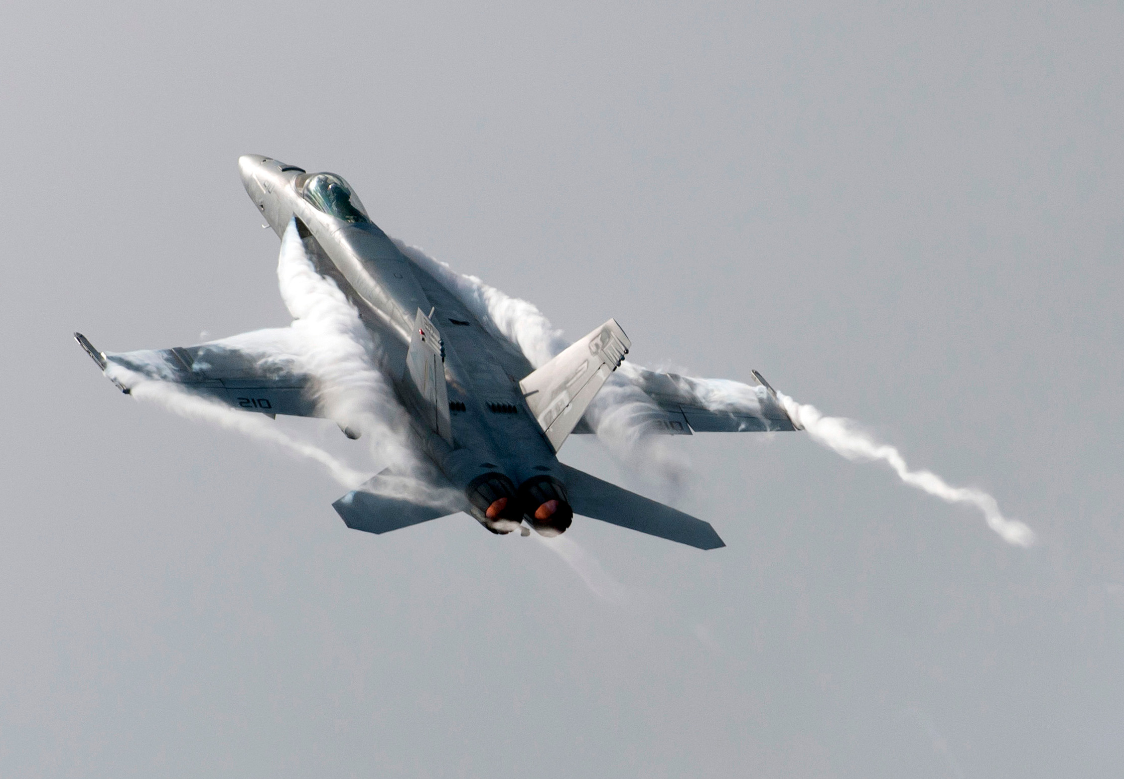
Based on the data in the IET report (which is an excerpt from the Book "Pulse Doppler Radar by Alabaster) the missile seeker has the following values: Range gate based on 4us pulse and chirp pulse compression 20m Beam width 12° based on low Ku band seeker in 7 inch missile body (like AIM-120). Velocity gate 7m/s based on 32 point FFT. The sensitivity of such a seeker to chaff will be highly dependent on geometry, for several reasons: - The range gate cuts the chaff bloom efficiently for a hot or cold target geometry (10m bloom distance before passing out of the range gate) - The angle resolution is not involved in a hot or cold target but very much so for a flanking and cranking target. The angle resolution is 3000m at 8nm, 1500m/4 and 750m/2. As the target will be somewhere in the middle, the chaffs affecting distance is half this for a flanking/cranking geometry, so 1500/8, 750/4 and 375/2. The chaff has the time to bloom to a reasonable size in this distance (the time for the aircraft to leave the cell is irrelevant as the seeker follows the aircraft with it's monopulse processing, thus the chaffs working distance is around the given values). - The doppler processing will attenuate the chaff, as it retards fast to the speed of the ambient air. The term ambient air is important as an aircraft creates strong vortice mats in flight. The first picture show the vortice mat created by a 1G flight of the Citation. The more G then stronger vortices, and for a straked aircraft there are more vortice trails than off the wingtips, second picture. This shows the condensation streams = low pressure = high local velocity of the air but does not show the full extent of the vortice mat (combine picture 1 and 2). What one can conclude is a hot or cold low aspect aircraft will have a low effect from emitted chaff. The radars range gate cuts the amount of chaff and the high in-effect doppler gate (closing or receding speeds are high, the 7m/s doppler bins around the target doppler are then effectively filtering out the chaff that's inside the range gate and is operating in the 7 low doppler bins (based on a maximum vortice radial speed of 50m/s). A cranking aircraft turning through the flanking position achieves three things: 1. The resolution goes from the short range gate to the wide angle gate. 2. The turn creates strong vortices that have local speeds of say 0-50 m/s (anyone's guess, but this seems reasonable inside the half angle gate) 3. The turn forces the missiles doppler processing to follow down to the region where the vortice trapped chaff has radial speeds that fall inside the the tracking doppler bins. The missile senses the clutter situation continuously through the many digital range and doppler gates and for a non-low level intercept it's geared to a low clutter passage through zero doppler for the target. Chaff deployed as the aircraft goes from high aspect, through the flanking position and out the other side will be effective in very different manner than chaff deployed in a hot or cold geometry. It will have time to bloom before angle cut-off and it will have radial chaff speed components in the doppler bins the radar uses for tracking. DCS is wise in staying away from modeling this too closely as it's sensitive stuff. But a simple model should contain a couple of parameters: - The geometry when the chaff bundles are deployed, where a high aspect geometry shall increase the probability of effect. The probability of effect in low aspect geometries shall be low. - The targets G when entering the high aspect shall have an effect. High G when crank through zero doppler shall increase probability of chaff effectiveness. - An effects constant based on the resolution capability of the tracking radar. A missile has the angle resolution problem (the SAMs have larger dia bodies but also 2/3 to 1/2 the seeker frequencies of the A-A missiles), a fighter or SAM radar is much less affected by this problem (their beamwiths are 1/4 of the missiles).