Jocman
-
Posts
160 -
Joined
-
Last visited
Content Type
Profiles
Forums
Events
Everything posted by Jocman
-
As I understood, the STM32 analog input are working but the resolution isn't the best, so using an external ADC fix the problem and gives a better resolution I'll have a search for discord. Anyway, reading the freejoy documentation it seems that (as in my previous post) the wiring could be as descripted. But before etching a PCB I'll try on discord channel (hoping to get into...)
-
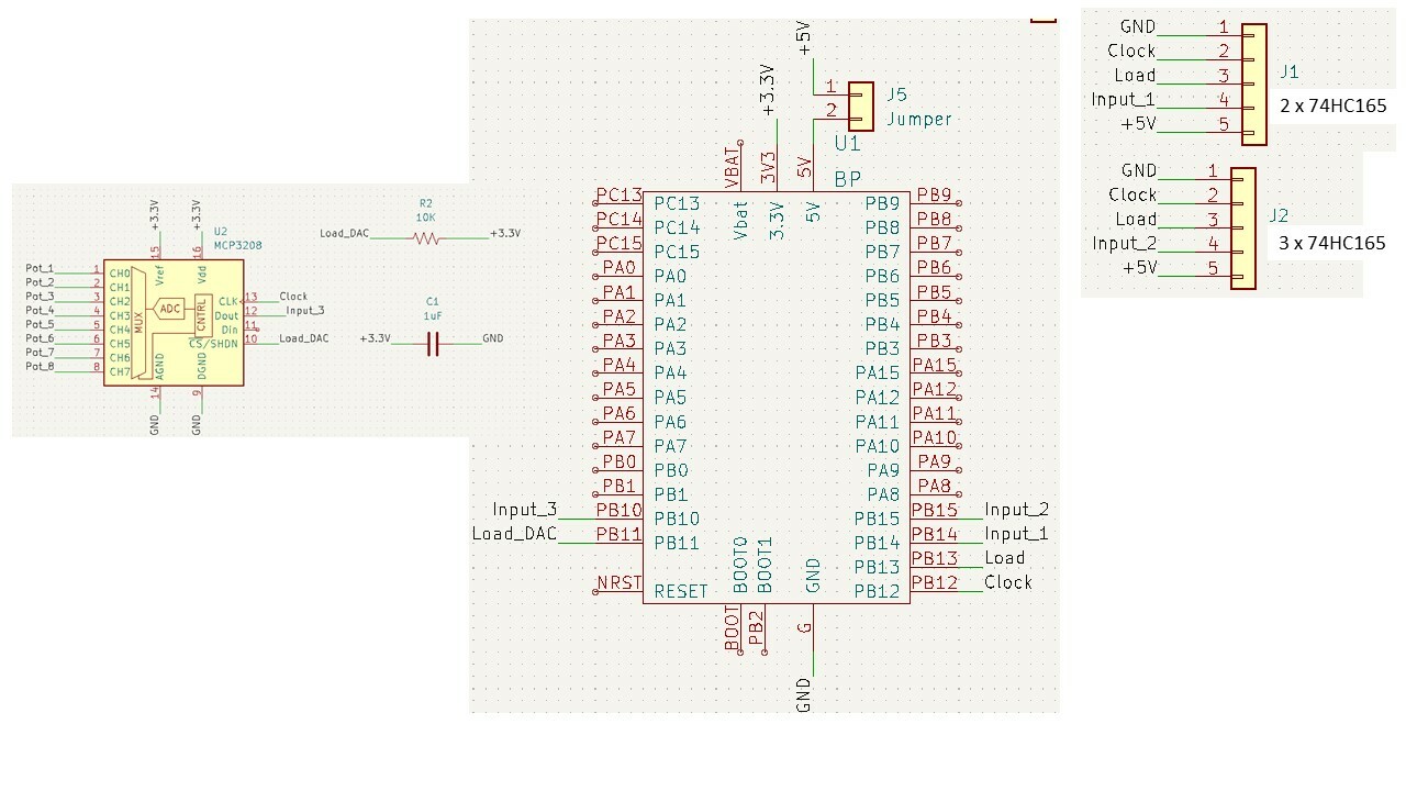
Yep, you're right, this could be an easy and maybe more reliable solution, even thouh I've to read the doc, considering I made the slave boards (with the 74HC165 chains) and see how to wire them to the card. What can I say? DIY sickness? Anyway, as I already made the 2 slave PCBs and got the DAC, I'd like to try the quest. Keeping studing, maybe the solution to my question could be: - cyclic shift register chain CLK + collective shift register chain CLK + MCP3208 CLK > all to SPI SCK pin on STM32 - cyclic shift register chain DOut + collective shift register chain DOut + MCP3208 DOut > all to SPI MISO pin on STM32 - cyclic shift register chain Latch > to pin X on STM32 - collective shift register chain Latch > to pin Y on STM32 - MCP3208 Latch > to MCP3208 CS on STM32 Could this work?
-
Hi all. As my home cockpit is getting on (my wife says she can see the light at the bottom of the tunnel, but I honestly not yet....), I' starting to work on the home made controls (cyclic, collective, rudder). Freejoy is my choice for the quest, so I started etching the PCBs. The cyclic is based on 2 shift register 75HC165 daisy chained, the collective on 3 shift register 75HC165 daisy chained: every PCB will host the shift registers.. As I will need 6 analog axis, I wish to ad an MCP3208 DAC. The PCBs for cyclic and collective are done, now I'm working on the main PCB (ST32 + MCP3208). Now my doubt: how to connect the MCP3208? The shift registers can share clock and load pins, the cyclic will have ad additional Input 1 pin, and the collective an additional Input 2 pin. As the MCP3208 owns a Clock and Load pins too, can these be shared with the 75HC165, or they need separate pins? As you can see, I planned to share the MCP3208 Clock pin with the 75HC165: is this correct? Attached a schematic related to second option (MCP3208 on separate pin). Your opinion and suggestion are obviously welcome. Thanks Jocman

-

Thinking to quit, but it deserves one more (or more...) chanche on RS485
Jocman replied to Jocman's topic in Home Cockpits
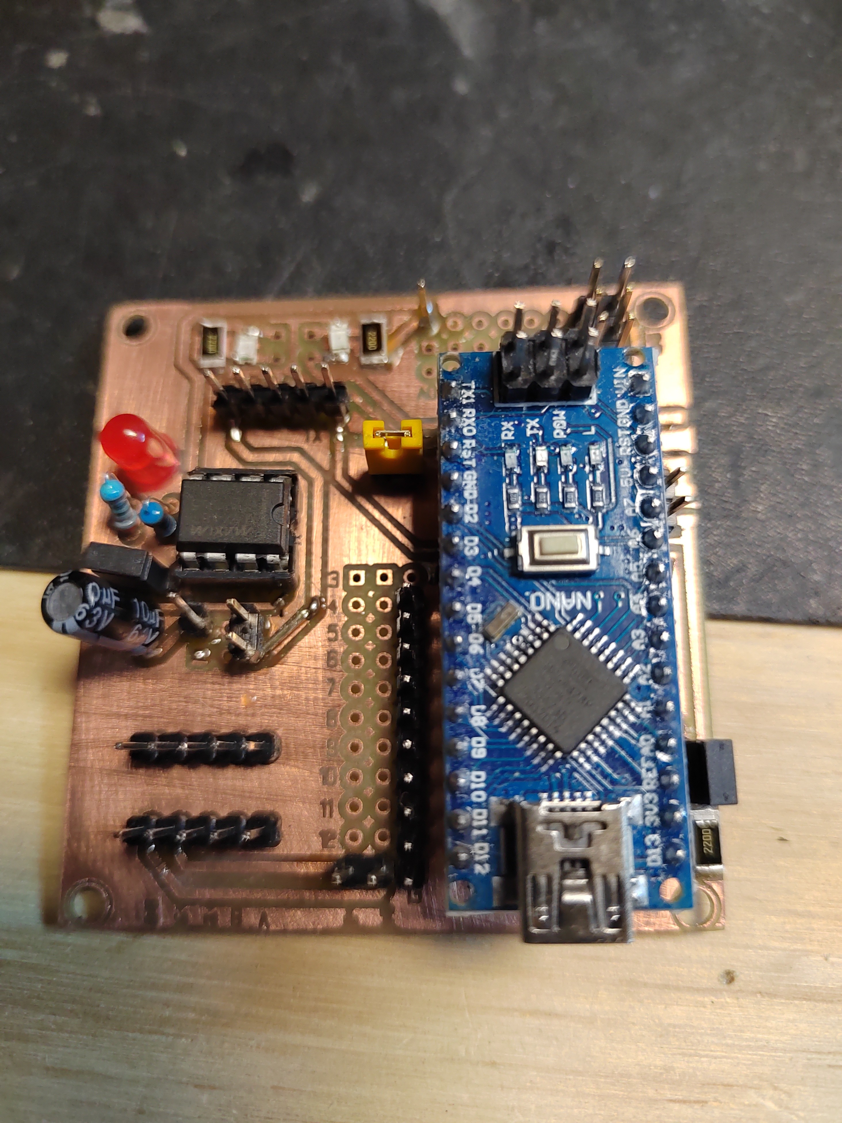
Slave proto made. Not all the components are present, but just to test if everything works. Btw, for the final version i'll change something: - Max487 feeded directly by arduino's +5V (keeping the possibility to select if feed arduino by 12 or 5V) - same thing for the 2 led Tx/Rx - added 2 leds to indicate the presence of 5V and 12V Next step, a new master pcb (but i'm waiting for the components from China) and a RS485 hub
-
Thinking to quit, but it deserves one more (or more...) chanche on RS485
Jocman replied to Jocman's topic in Home Cockpits
Thanks for your sharing, Vinc. Here's my possible new version of PCB (i use kicad). Is intended to be used with Nano (onboard) or,alternatively, Mega (wired). More, there is a rs485 through (from blue73 design). Possibility to feed Nano with 12 or 5 V (using a jumper) Jumper to power on/off the Max847 Jumper to enter in "onboard program mode" (i read on italian forum you need just to break the wiring RO→Rx to do it - hope is right). Btw,is it not enough to unpower the Max487? Max487 power led rx/tx led (with plugs to wire external led) 12V rail 5V rails Now I should make a prototype and test it. and someway fix my doubt on shielded/twisted wires (well, the distances could be important)....
-
Thinking to quit, but it deserves one more (or more...) chanche on RS485
Jocman replied to Jocman's topic in Home Cockpits
Not sure to understand (sorry, my poor english); currently I'm not feeding anything from the arduino 5V out. All 5V to the various stuff are provided by the PSU (5V 30A), wich, currently, feed arduino too via 5V pin. so Arduino is not overloaded with current In my plans for new PCB design, I'll use the 12V to feed Arduino via Vin pin, thus the 5V pin will be not connected to anything else. Aside this, anything about the need / not need to use twisted/shielded/both wires for AB signal? -
Thinking to quit, but it deserves one more (or more...) chanche on RS485
Jocman replied to Jocman's topic in Home Cockpits
Ok,i won't do it. So i think i'll separate and use the 12v only to feed the arduinos and the 5v to feed the max487 chips and all the other stuff (leds,max7219,and so) I'm going on with re-design my PCBs,so i keep waiting for your advices. -
Hi all. After several years, I was pretty sure to see "the end of the tunnel": I realized almost the 90% of the physical cockpit (panels with leds, switches, displays, etc), and almost lost my right thumb while working on the metal body of the cockpit. Following the HanSolo RS485 tutorial, I realized the first working prototypes of RS485 network, then developed my "point of view" of PCB for the Nanos and Megas to use (about 30 in total). But things aren't going in the right way: most of the switches (7 nanos + 1 mega connected until now) seem working properly, but also strange behaviour: - delay in responding: even 1,5 sec between the press of a btn and the "virtual" answer, hoping it doesn't get "virtually" stucked (the physical btn is released, but the virtual keep being pressed); it happens even with the switches sometimes... - the mega giving no sign of life; until I physically unplug the TX/RX connectors and re-plug them.... - I tried to test some leds by the lamp test button (by pressing the virtual one): all the nanos got reset and restarted; I tried again a couple of times, and I had to reload all the sketches because they stopped giving any sign of life..... After reload the sketches, they started to work again (but with the above problems.....) Well, the solutions: trash everything and switch my mind to get a consolle and play only with platform games (horror and abomination!), or give it a chance (or more...) by changing something or all (and my right thumb thanks...) So, I will ask you for some info because of my raised doubts: - Can I power arduino with both 12 and 5 volts at the same time (one direct to Vin, the other on +5)? Until now I used only 5V (for everything), but maybe arduino could work better by using 12V and let him manage his internal power. But in case I'll have even the 5v option - Still about power: is fine to use a single PSU (my intent is to use an old PC PSU to power all the system-now I'm using a bench PSU)? - RS485 A-B signal: the 2 wires have to be twisted/shielded/both or 2 straight wires are enough? I see lot of you using a 5-6 wires flat cable, but on some electronic forum they talk about twisted/shielded wires.... - Still A-B signal. I've an alarm shielded cable coil (red/black 1,5 mm and 4 wires 1 mm): may I use the black and red for +12 and +5, and one of the small wires for GND (having so other 3 wires for A, B and 1 jolly)? - The master can manage 3 lines: is it better to divide the workload among the 3 lines, or even just one line shouldn't have any problem to manage tens of slaves? - I've seen that Blue73 (https://forum.dcs.world/topic/187748-modular-panel-wip/?do=findComment&comment=3775559) use the RS485 bus even to wire all the arduinos reset pin over the bus network. There's some reason to? - For my PCBs I'm using MAX487 chips; normally, for MAX486 chips I've read to put a 120ohm resistor between every A-B terminals. But if I'm right, it doesn't need with MAX487, is it? I'm sorry to annoy you with all those questions, but.... Thanks in advance for your help
-
Well, after several days of testing (and swearing) suddenly something's changed. I don't know what....I just re-loaded the sketch on the board. For the sake of honesty, I tested an RS485 chain with 2 Nanos and 1 Mega. The 2 Nanos are correctly working (they communicate), but initially the mega kept not communicating. I tried (desperation?) by unplugging the dupont wires fromt TX0/RX0 and plugging into TX1/RX1 (with all the system still powered and connected to the master.) The mega started to communicate..... Then unpowered the system and powered again: the mega didn't work. Unplugged the wires again and plugged back to TX0/RX0: it started to work again.... Unpowered then powered: the mega didn't work again.....unplugged and plugged the wires again (this time on the same TX0/RX0): the mega works..... I don't understand, what's wrong???
-
Thankyou very much for your suggestion. I'll read the post and meke some test. I'll post in the next days about the news.
-
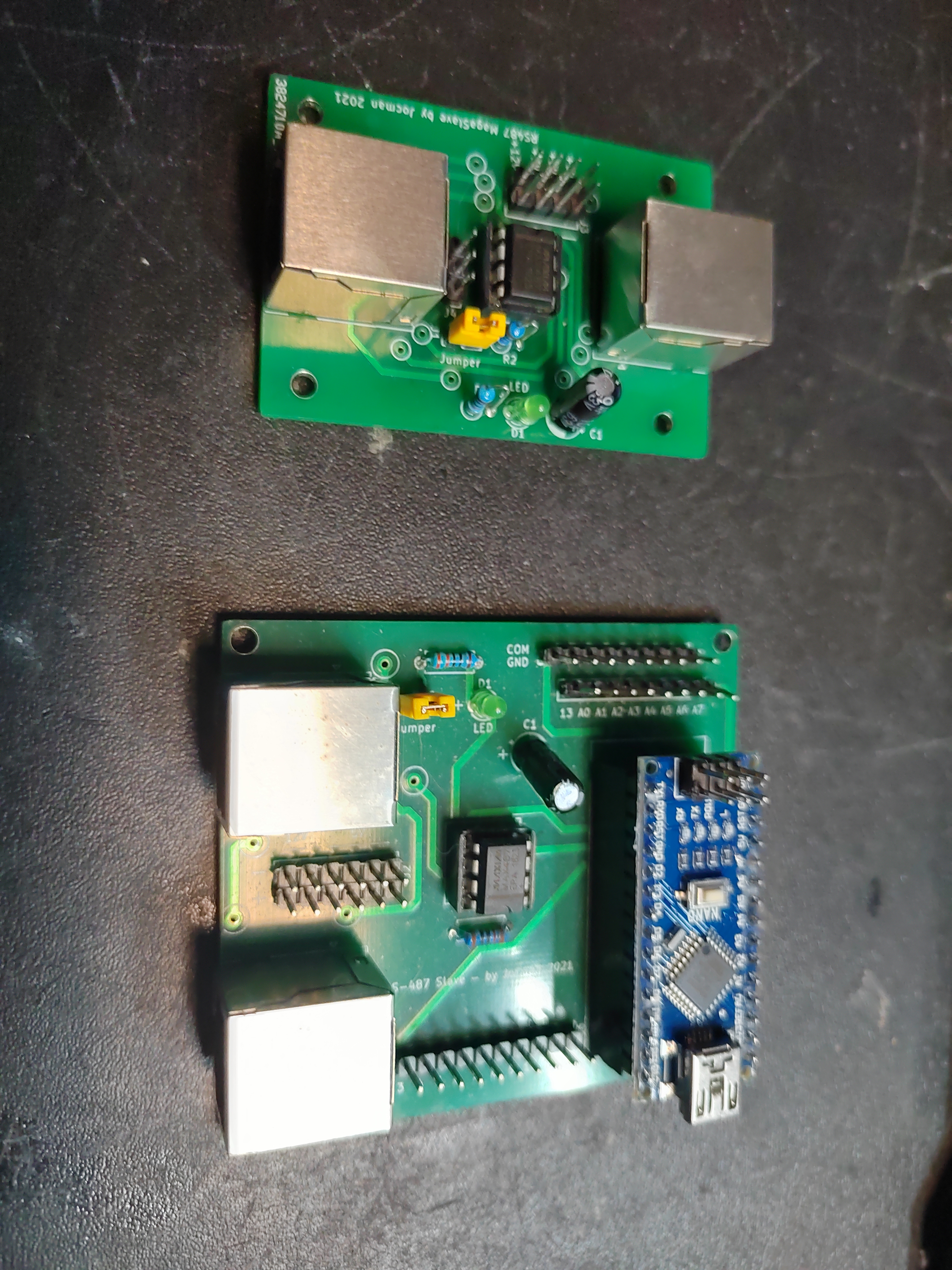
I made 2 interfaces. The one for the Nano hosts a Max487 chip (and the needed components), the connectors for the nano board and the pins for wiring the panels switches/leds/others. As the Nano board is very small, it is directly mounted on the interface PCB The one for the Mega board is smaller, as it hosts only the Max487 chip and the needed components. This interface is connected to Mega board via wires: the enabled pin for RS485 is the #2, while TX and RX are wired to TX1/RX1 pins. (attached the image of both the interfaces) With some dupont wires it's "easy" to connect "on the fly" the Mega board to the interface made fo the Nano and viceversa. This way I made the cross test, so I'm sure the interface for the Mega board works, thus the problem is the Mega board (i'm referring to a Mega board as slave). When I use a Nano with both type of interfaces, by pressing the physical button the virtual button is regurarly pressed. My plans are (or were??) to connect most of the panels to Nano boards, but for some panels (as the PVI800 keyboard) I'd like to use a Mega board via RS485 The RS485 master is obviously a Mega board direct via USB.
-
Hi all. I've read several similar posts,but no solution worked to my issue. I self-made 2 type of rs485 interfaces (using MAX487): one such an embedded system for nano, one just the rs485 for Mega. The Nano embedded interface works very fine,all the Nanos connected work fine. But now I'm trying to connect a Mega (for the PVI800 keyboard). Well,it simply doesn't work..... I made some crossed test: - connect the Nano interface to Mega: it doesn't work - connect the Mega interface to Nano: it works - connected Mega as IRQ Serial : it works - connected Tx/Rx pin over all the Mega connection (tx/rx 0 to tx/rx 3) but no working When Mega is connected to its dedicated rs485 interface, the RX led stays off and the board doesn't work..... I tried with 2 different Mega Boards,but same result: if connected as IRQ Serial, both the boards do their job, but if connected via RS485 no way to make them work. Honestly i don't understand..... Both kind of interfaces are correctly working,so the problem is Mega, but why? Jocman
-
Hi all. I tried to find out something about,but no luck.... Sifting through the .h library's files (dcsbios fork),i found several very interesting functions, like (i.e.) the excellent SwitchWithCover. While it is almost clear what should this function do, it is not really clear how to use it. By reading the code inside the library, you can get the way to use it,so did I. Nevertheless, by sifting the other .h files (like SyncingSwirches, RotarySyncingPotentiometer,etc etc) there are a lot of function (at least resting on their names) potentially very interesting and / or useful. Unfortunately, even digging into github fork's repo, you can't find a complete library reference (nor examples) of the improved dcsbios library. The only reference (and well documented with examples) reported is about the Ian's "original" dcsbios library, so is missing a lot of function. My question: does it exist a complete library reference of the Fork's expanded library, so to fully understand all the available functions, without be restricted to the...standard used functions (the ones documented)? Thanks all in advantage
-
DCSBIOS and KA50 - coding issues (Switch+switch cover and other)
Jocman replied to Jocman's topic in Home Cockpits
Going on with coding, time to pass to LWR. Easy one (8 LEDs and 1 BTN), nevertheless...... As the hardware test shows all the LEDs working (just a simple cycle in arduino), once launched the sim there's no way to see the BTN working..... You can push it whenever you want....nothing.... I double checked (but even triple quadruple, etc etc) everything about the BTN (DCSBIOS code, hardware wiring, etc etc) but nothing to do. By using a test sketch (the standard arduino example sketches) the BTN (so as the hardware wiring) works fine...... Any idea? -
DCSBIOS and KA50 - coding issues (Switch+switch cover and other)
Jocman replied to Jocman's topic in Home Cockpits
About the T suffix I confirm, the FlightPanels library (at least, the one I got) have the T as suffix (reading directly the library). I got it from GitHub, or there's another website more updated where to get it? Currently, I wrote the code by manually building the line and getting the code from the HUB aircraft reference, but is there any aircraft reference adapted to FlightPanels? Nevertheless, by giving the command like Switch2PosT I get an error message; giving it without T, it does work.... Nope, you're right, it doesn't. But i made a try. Compiled the arduino file with the FlightPanels library and launched the HUB. It works. BTW, so as HUB is not updated (at least, until now) are you suggesting me to use the "old" command line DCSBIOS SOCAT? If so, wich release? And, when you say "some modifications can't be used with Hub.", what are you referring to? I know I'm almost....poor in new developments, but I'm spending all the freetime I can in trying to finish the building of my cockpit, and honestly I'm not so updated.... Thanks Jocman -
DCSBIOS and KA50 - coding issues (Switch+switch cover and other)
Jocman replied to Jocman's topic in Home Cockpits
First of all, thanks for your support. About the FlightPanels fork, I went to this alternative last week. Honestly, since I've been starting coding about 3 weeks ago, I coded a couple of...."easy" panels, meaning just push button and leds, with or without display. I'm referring to PVI-800 and UV-26, and a couple of other panels with no switch covers. Since it was a little bit long, i'm quite reluctant to leave the "old way" considering the follows: - the release of DCSBIOS HUB is, to me, a great solution in managing the system: connecting to sim, and managing the control reference... piece of cake - Reading the docs about the fork, I'm getting a little bit confusing...I'm not understandig if by adopting the fork, i can keep using the HUB to connect the boards to the sim, or i've to "downgrade" to the previous management system (i.e. as I reed, the fork suggest to use the old chrome control reference, instead of the new one in HUB: is there any reason to not use the new one? the control reference isn't the same?ok there's the "T" suffix now, but the rest of?) - By examining the new fork libraries (at least about the switches section) I've seen the commands now have different names (i.e Switch2Pos is now Switch2PosT) and evend the code side differs from the Ian's original one. This means, by adopting the fork, I'll have to recode everything to match the new library. Well......I could even switch to the fork, but it will worth? I'm not again it, but I just wish to understand.... In my spare time, I'm trying to see if someway I can create a code similar the fork's for the switch cover to merge into the "original" Ian's library. I'm not so into C++, but who knows.... Beside this, about the rotary switches and their pins? Thanks Jocman -
Hi all. Still stucked in my home cockpit building since ....... you better you don't know about, I'm now starting seeing the light at the end of the tunnel. Hardware is 75% done (3 or 4 non functional panels missing, and the main structure), electronics (PCBs at 99% and full working - untill now), and time is come to start playing with coding. Not really a big issue, Ian made it really easy. Nevertheless, I'm getting some puzzlements. The main one: the "switch cover affair"...... I've read several post here in DCS concerning the affair, but it seems all of them are all "joystick user oriented" only; it means I'm still fighting with finding a solution. I learned that Ka50 LUA philosophy about the command mapping is very different from the...standard one (A10 and F18); of course, in the worst meaning.... As many people, I tried the easiest cheat: programming the same arduino's pin to drive both commands set (cover + switch). Obviously, it doesn't work....too much easy, uh....? Maybe the next (easy?) solution could be the alteration of LUA files by merging the 2 individual code lines (cover and switch) in one, so my questions become: wich LUA files are involved? And the most big question: is there anybody out there who can simply exemplify how to merge the 2 lines? Moreover as Ka50 LUA philosophy striles a discordant note....... Once understood the mechanism, everyone (not only me) interesting in such stuff would be very grateful. A second issue is related to using a rotary switch. Exemplifying: the Datakling mode selector is a 4 position rotary switch, and the related DCSBIOS code drives 4 pins; someway, it makes sense: all the 4 positions have a meaning. But considering the overhead's navlight switch (but the same for many other multipos switches): is a 4 way switch (OFF/10/30/100%). Find a 4 way level switch, well....so I opted for a rotary switch. The DCSBIOS code drives 5 pins.... My puzzling becomes: Why 5 pins to drive 4 positions??? And: can only 3 pins drive this switch? after all: pin 1>10%, pin 2>30% pin 3>100%, no pin> OFF My coding tale is just begun, so it is very likely I'll get stucked somewhere, altough I hope not, this case I'm afraid I'll bother you again..... By now, thanks in advance to everyone will support me . Cheers Jocman
-
Al momento sto andando avanti a dischi multipli per ogni cosa ke faccio,ogni disco con il suo OS e io software che mi serve,a seconda di cio che voglio fare cambio HDD : - Os + programmi creativi (x stampa 3d,lavorazioni CNC,etc) - Os + DCS - Os + FS - Os dedicato a cazzeggio internet, giochi vari,varie ed eventuali Probabilmente è un po esagerato,ma almeno cosi nn mi sputt...no tutto in caso di problemi. In passato(quando usavo un solo Os xper tutto) mi sono sempre trovato al punto che a causa del zozzume (soprattutto derivante dal traffico di rete) mi rallentava tutto etc etc. Da quando faccio cosi,ho tutto molto piu leggero e funzionale per il caso specifico
-
Sto passando ad un sistema su SSD solo per DCS,e quindi sto vedendo cosa prendere. Mi orientavo su un SSD da 1Tb,ma per sicurezza mi è venuto da andare a vedere se era sufficiente (beh,direi di si,o almeno me lo auguravo),cosi ho preso la lista delle mie "proprietà" DCS (9 moduli tra velivoli e scenari) e ci ho aggiunto DCS world. E ovviamente poi ci sarà Win10. La cosa strana è che per qualunque modulo andassi a vedere il setup ottimale,tutti richiedono 120Gb; anche World richiede 120Gb..... Ora,va bene che tutto è possibile,ma è mai possibile che qualunque componente DCS occupi "d'ufficio" 120Gb???? Anche perchè cosi facendo non basta un SSD da 1Tb per installare i soli miei "possedimenti",a cui vanno poi aggiunti World e Win 10. E del resto,anche prendendo un SSD da 2Tb,basta prendere un paio di altri moduli (scenari per lo piu che mi interessano) e riempirò pure quello.... Insomma,mi sembra un po strano.... Dove posso reperire i dati relativi allo spazio effettivamente richiesto da ogni modulo? Andrea
-
Well, thanks for the replies. About the models, I think maybe it will be better to pay a little bit now, but get a good (high ?) level device, more than get a cheaper one, then feel to want more, get a new one and keep the old one "on your bal...s" trying to sell it undercost. The Valve Index, currently, seems to be the one giving more features (not least the refresh rate), followed by Vive Pro. I was considering Pimax for the FOV, but something leaves me someway dubious..... BTW, I'm planning the attend the Cologne Gameshow the next month, hoping to test some headset, and in a...professional way. Couple of months ago I went to a local fair, they had some headset to play with (the Vive first generation), but (I hope) the setup was really a sh..t, the images were really a bounch of squares (really, squares, not pixels!), unconceivable! It seemed to me the first headset I played with (it was the far 1995) with Doom: for that year it was awesome, but not today!
-
Hi all. While I'm still going on with my homemade cockpit (Ka50 - endless....), I'd like even to fly my huey, the forthcoming F16 and maybe some other else. As it will be (i guess) inconceivable to build an individual cockpit for each of them (it would be awesome, but first of all, the place for each of them, then the cost, etc; and out of scale, the wife.....), the good solution will be the VR. It's quite some time I'm reading and collecting infos about the VR market, expecially in this last time I'm considering (in the order): Valve Index, Vive Pro and Pimax. Well, maybe the day I'll finally get my VR headset (if I keep going on this way....) many other VR products will be made, but I've a big...perplexity about, and I beg perdon for the silly question. I see, for every headset, they report to Steam environment or such. As I abhor all of these streaming/online/etc provider (reason why I'm getting all my DCS modules as standalone), I'm wondering if the VR headset will work even with no reference to them. I mean (low level talking): despite the compatibility with Steam and others, the VR headset will be seen like a "SciFi monitor" (ok with the VR features), or someway I will have to depend from these online platforms? Thanks Jocman
-
Hi all. I'm trying to program DCS-BIOS with the MAX72XX to drive annunciator, warning lights, etc etc in BS2 module. I've been watching some sample program (caution panel) found in the forum, but (unfortunately) they are made for AC10 module. More unfortunately, the led addressing for AC10 module's caution panel is....easy. So, to create something similar for BS2 module, I'm thinking about such logic structure (array or matrix) adapted to the BS2 led addresses. My question: LED addresses in DCS-BIOS ar something like: 0x1818 or 0x184a, etc . There are more led with the same address (es. 0x1818 , but the mask is different (0x0001, 0x0800, etc) So, every led is identified by (i suppose) something like 0x1818+0x0800 or 0x1818+0x0001, etc. I'd need to know how DCS tell arduino the led ID, so to use this ID to manage the led with arduino. As it can be very possible I'm totally wrong, that case can someone explain me how it works? Thanks all Jocman
-
I give myself the answer. After some test (I tried all the rotary - or multi - switches in the Ka50 cockpit), I can say the following: In the overhead panel, the 2 switches NavLights and WindshieldWiper can be wired to 4 pins instead of 5 (as reported in the reference), saving this way 2 pins. In fact, the 5th position is such a "ghost" one: if you click the cockpit switch, it will works only in left, center, right, down position. Using a physical switch (a rotary), the first 4 positions drive correctly the 4 values (off,10,30,100), but the 5th moves the lever upward (there's nothing functional in the sim about this 5th position). Same issue about the windshield wiper. So, I can say this 5th one can be deleted without any problem; I also modified the code [font=Times New Roman][size=3][font=Courier New]constbyte opWindshieldWiperPins[5] = {[i][color=red]PIN_0, PIN_1,PIN_2, PIN_3, PIN_4[/color][/i]};[/font][font=Courier New] [/font][font=Courier New]DcsBios::SwitchMultiPosopWindshieldWiper("OP_WINDSHIELD_WIPER", opWindshieldWiperPins, 5);[/font] [/size][/font] to [font=Times New Roman][size=3][font=Courier New]const byte opWindshieldWiperPins[4] = {[i][color=red]PIN_0, PIN_1, PIN_2, PIN_3[/color][/i]};[/font][font=Courier New] [/font][font=Courier New]DcsBios::SwitchMultiPos opWindshieldWiper("OP_WINDSHIELD_WIPER", opWindshieldWiperPins, 4);[/font] [/size][/font] I don't know if is correct, but it works fine Same thing for the windshield wiper No such issue for the rest of the rotaries (no need of change and, unfortunately, no pins to save) If I wrote/made/told something wrong, please correct me
-
DCS-BIOS: problem with first attempt - master caution
Jocman replied to Jocman's topic in Home Cockpits
I think I'll do it, as I've been doing for my previous project (never airborn, just left on the taxyway....). Don't think I'll bring new solutions, but who knows? -
I start this (little) new topic just to have a clarification about the SwitchMultiPos function. As it will be used to manage rotary switches or similar, I'd need to understand this: i.e. the NavLight have 4 sets: 10/30/100/OFF, so I expect 4 position (4 pins), but the reference reports 5 position (5 pins). Same issue for all the SwitchMultiPos in the reference. Can you explain the issue? why there's always 1 pin more than the switch positions? Thanks