Search the Community
Showing results for tags 'arduino'.
Found 11 results
-
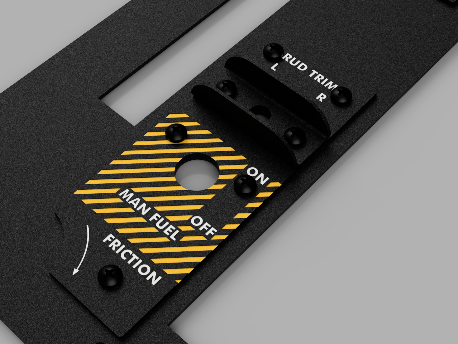
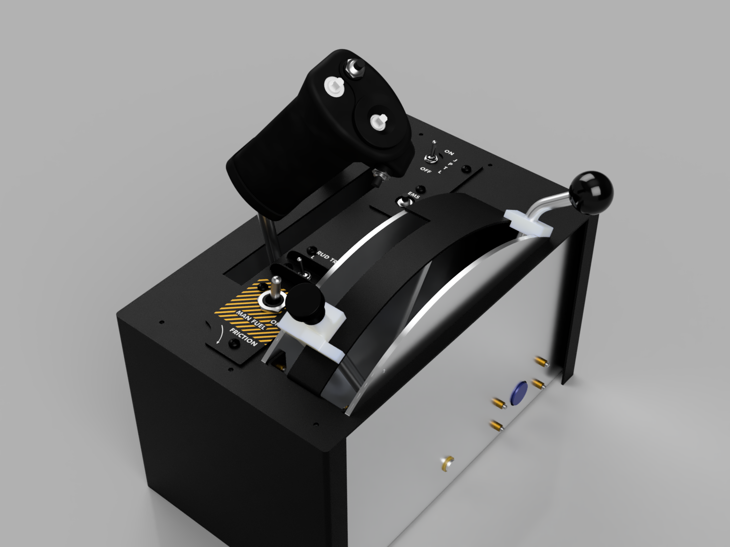
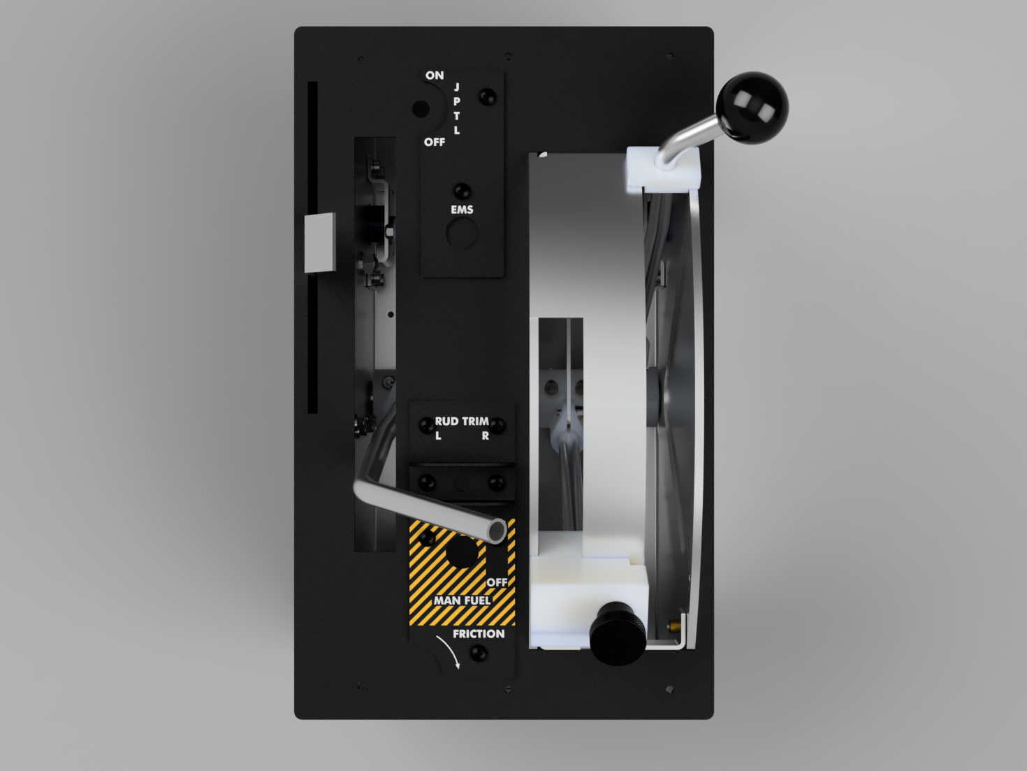
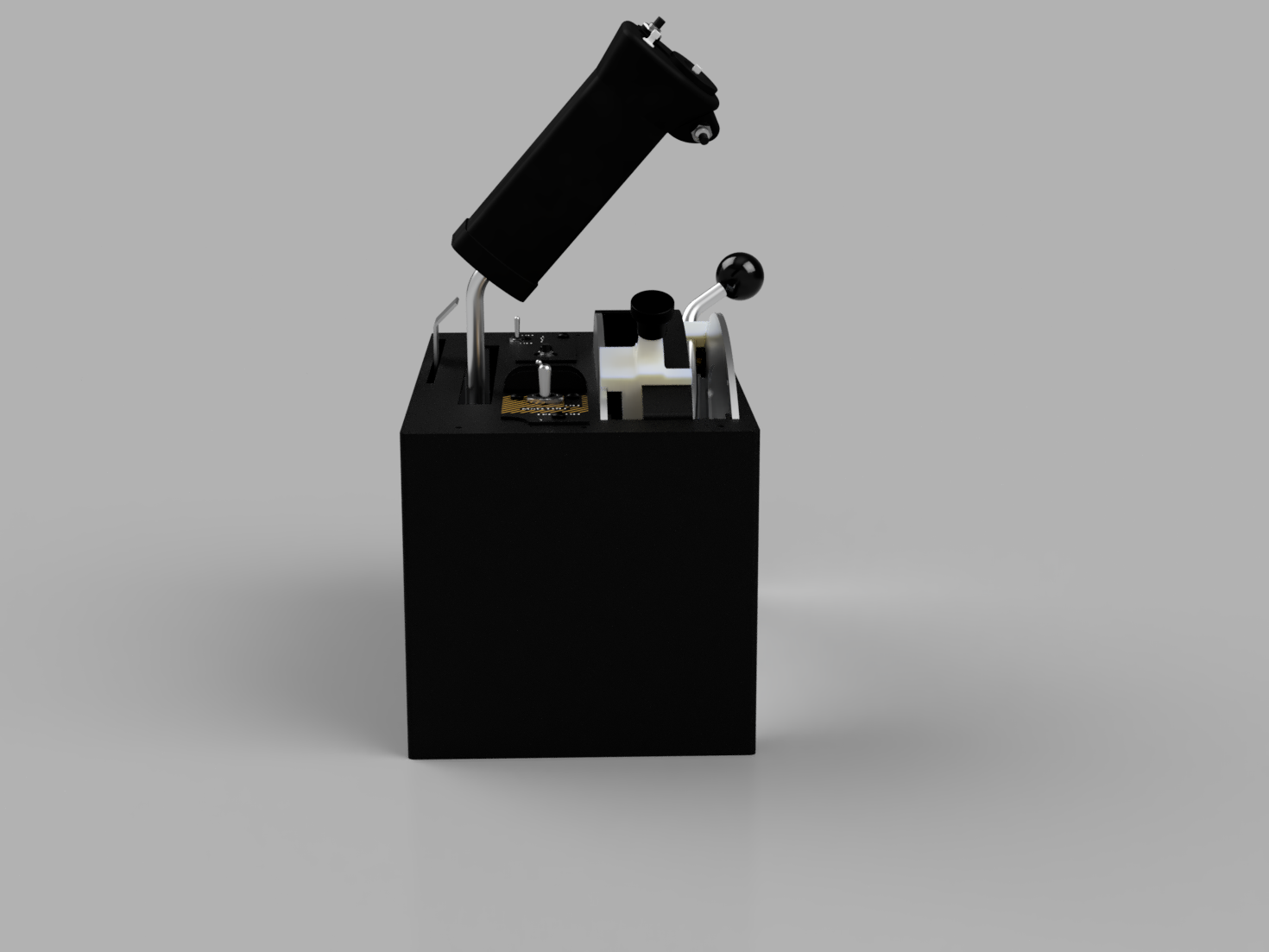
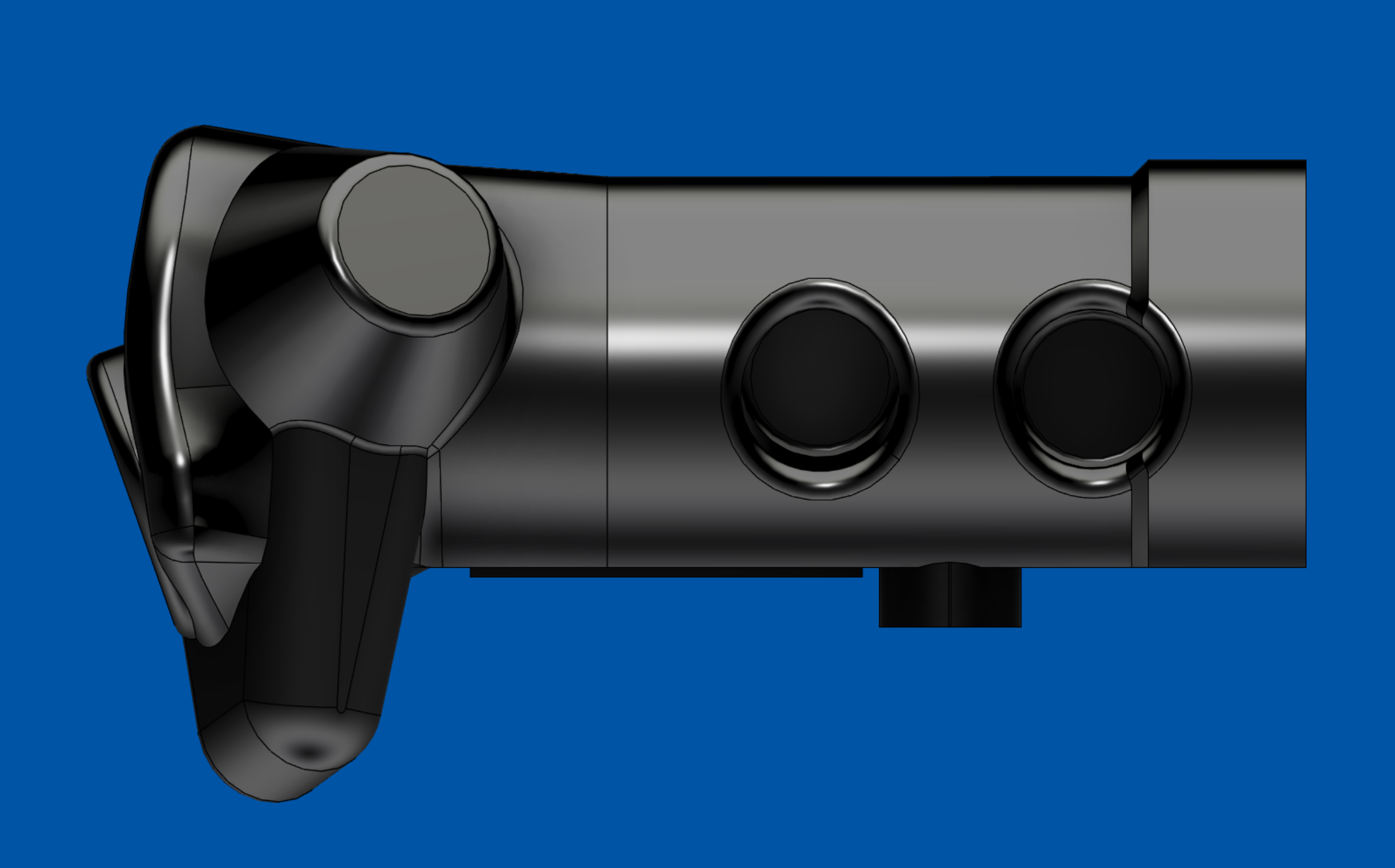
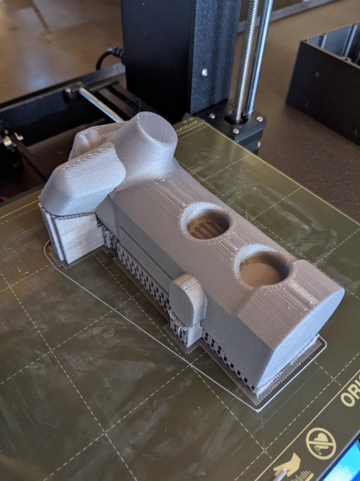
I'm making a dedicated thread on a throttle nozzle quadrant build that I'm working on. This is something that started a while ago with a pretty detailed design effort that was put on hold for two reasons: 1. my 3D printer was having issues that needed to be investigated, and 2. designing the throttle grip was quickly determined to be too difficult based on the information I had at the time. Since then I have bought a new 3d printer and the old one has now been stripped down for parts for the quadrant. I have also stumbled across several excellent photos from @mattjonesgr9 that were posted on a UFC build thread. This is now enough, along with a short break in work travel madness, to allow me to hit this project hard again. I'm hoping I can keep enough momentum to get a working prototype finished in a few weeks. These are the original renderings of the quadrant enclosure assembly: I did manage to print out this first grip effort, but it was so far off the mark, I didn't know where to start. Since then I have come up with this design for the shell: Whilst not perfect, for a solid body, it's close enough. I've also scaled down the component by a factor of 0.9 as the printed version felt a tad too big for an ungloved hand. This first prototype won't be made of sheet metal as originally planned, but will be assembled from 2020 extruded aluminium and 3D printed parts. I will also be using a hall effect sensor for each of the three rotating axis instead of potentiometers.

-
 PLEASE post working sketches for dcs modules here many thanks
 -
I'm creating a display to show the active frequency on the A4, but unfortunately the code to be entered is wrong, the separator lines (-) are not recognized by arduino ide. void onArc51-freq-xxxxxChange(unsigned int newValue) { /* your code here */ } DcsBios::IntegerBuffer arc51-freq-xxxxxBuffer(0x84c6, 0xffff, 0, onArc51-freq-xxxxxChange); does anyone know how to help me ?
-

Mmjoy2, Encoders and buttons Problems
benebearded posted a topic in PC Hardware and Related Software
Hi Guys! I'm assembling a button box, I've already made similar ones and all without problems, Now I'm following the same assembly pattern and components, but I'm having a problem with the encoders where they keep clicking for a long time even after adjusting the delay, and the clicks are for both sides at the same time, I can't understand and find the cause, I added an image of how I made the connections, and a short video showing how it's working, and other than that, some of the buttons simply stop working even after I've already configured them, they just die without explanation. Thanks to anyone who can give me some idea of what's going on! I'm making 3 boxes and all three are having the same problem, and also some of the buttons stop working in the VKB button tester but in the matrix configuration in mmjoy they work normally, I can't find the error nowhere Wiring Diagram: https://imgur.com/a/OsJ1jGw The real box: https://imgur.com/a/MDbXww2 video in mmjoy2: https://imgur.com/a/54wK6wO -
fa18_simpit.ino I noticed theres not a lot of info pertaining to planning the circuits and building the code with "Arduino" and "DCS bios " or maybe its buried in the archives so I'll leave this here. This is my attempt to future proof my starting point on my flight panel build, in an attempt to use as little storage and pins as possible. you'll see I'm using a clunky but simple method to combine DCS bios global variables with ad-mux-library channels and also kept the loop as short as possible to maintain a high refresh rate as the build goes on that will likely change. I have yet to verify this even works as I am waiting for supplies and wanted a starting point with the code to familiarize with and test as i build. any ways let me know what you guys think
-
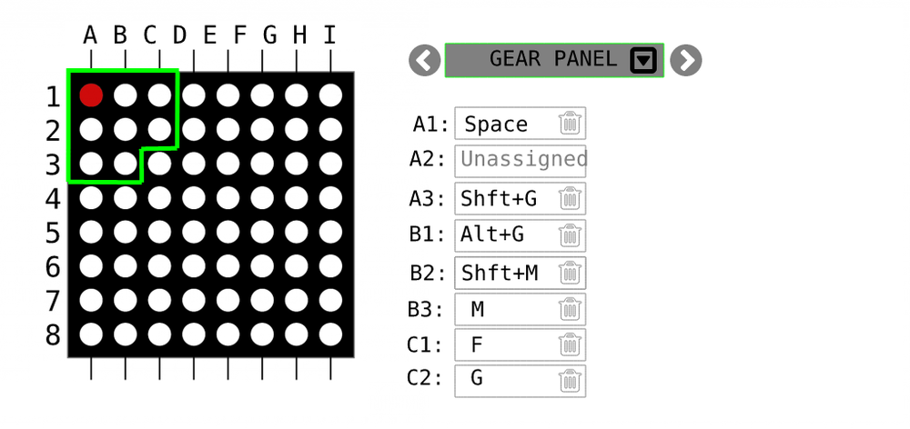
.thumb.png.d43db0aa51621a39a2161ec5c6fff372.png) Hello I'm in the planning stage of a simpit and what I already don't like is the hard wiring of components and having to use multiple arduinos in different spots. I want the whole structure to be more modular as in being able to reassign and rewire buttons to different locations without having to build new software for the Arduinos. So thinking of alternatives, here's my concept. Theory Can you think of a common computer input device that is capable of reading 1 million inputs 60 times a second ? Yes, an HD USB camera. These are typically able to send 720*1080 pixels of uncompressed RGB @ 60fps to the computer. Now, for the camera to read our inputs we have to connect each switch directly to an LED, and position these LEDs in a grid. We could also simply buy a ready made LED matrix. That means in theory we could now read 1 million inputs per second, but in reality we probably need some spacing between camera pixels to increase resilience. Hence, if we leave 9 pixels around each input pixel we could still read 100000 inputs @60 times a second. Mapping To match each pixel to a control input is fairly easy, this can be done in a raspberry PI or as a program running on your computer. Multi-stage switches can be mapped to a single LED using 200ø resistors in series, therefore controlling the LED intensity in multiple steps- Potentiometers can be wired to an RGB LED controlling a color shift from red to blue or green which can be detected by the camera. For example we could build the last 2 lines with RGP LEDs which can be wired to potentiometer inputs. I.e. LED 1,1 -> button 1 ( RED LED ) LED 2,1 -> button 2 ( RED LED ) LED 4,1 -> multi-stage rotation switch ( RED intensity ) LED 1,40 -> potentiometer input EDIT: On the software side you could group LEDs into "panels" and assign key combinations Pros & Cons The nice thing about having this LED matrix is that it works STANDALONE - without a computer, chip or software. It's just pure electronics and allows you to debug the system visually. The matrix would need to be enclosed in a box to not affect the camera with other light sources. You also don't need ANY programming skills. You could simply use my software and assign each pixel to a button with a point & click interface. The other nice thing is that this is not limited to DCS. Your hardware can work with any other flight sim, while the software emulates keystrokes and keeps your mappings. Now, to wire up 100s buttons to LEDs is certainly no easy feat. But im wondering if it's really harder than wiring up 100s of switches to arduinos - and writing custom software for each in DCS bios. Also dealing with and updating multiple arduinos is not very maintainable. A disadvantage would be that our input rate is now limited to 60 fps. So this input method may work well for switches or potis. But maybe it's not fast enough for your HOT firing trigger. Yet, i can only think of the firing trigger that requires really fast millisecond response times, any other input in my plane is totally fine at 60fps. Another disadvantage may be that we loose some accuracy with potentiometers. Due to converting them to RGP light and reading it through a camera. For things like flaps this may not be an issue, but if you use a poti to move a cursor on a map this could be more twitchy. Skipping the LED step An optimisation would be to skip the LED step entirely. How is a $30 USB camera able to serialise this much data and send it to the computer in a manageable format ? If we can somehow connect directly to the camera's serialiser we can save some work and gain more precision. Any thoughts?
Hello I'm in the planning stage of a simpit and what I already don't like is the hard wiring of components and having to use multiple arduinos in different spots. I want the whole structure to be more modular as in being able to reassign and rewire buttons to different locations without having to build new software for the Arduinos. So thinking of alternatives, here's my concept. Theory Can you think of a common computer input device that is capable of reading 1 million inputs 60 times a second ? Yes, an HD USB camera. These are typically able to send 720*1080 pixels of uncompressed RGB @ 60fps to the computer. Now, for the camera to read our inputs we have to connect each switch directly to an LED, and position these LEDs in a grid. We could also simply buy a ready made LED matrix. That means in theory we could now read 1 million inputs per second, but in reality we probably need some spacing between camera pixels to increase resilience. Hence, if we leave 9 pixels around each input pixel we could still read 100000 inputs @60 times a second. Mapping To match each pixel to a control input is fairly easy, this can be done in a raspberry PI or as a program running on your computer. Multi-stage switches can be mapped to a single LED using 200ø resistors in series, therefore controlling the LED intensity in multiple steps- Potentiometers can be wired to an RGB LED controlling a color shift from red to blue or green which can be detected by the camera. For example we could build the last 2 lines with RGP LEDs which can be wired to potentiometer inputs. I.e. LED 1,1 -> button 1 ( RED LED ) LED 2,1 -> button 2 ( RED LED ) LED 4,1 -> multi-stage rotation switch ( RED intensity ) LED 1,40 -> potentiometer input EDIT: On the software side you could group LEDs into "panels" and assign key combinations Pros & Cons The nice thing about having this LED matrix is that it works STANDALONE - without a computer, chip or software. It's just pure electronics and allows you to debug the system visually. The matrix would need to be enclosed in a box to not affect the camera with other light sources. You also don't need ANY programming skills. You could simply use my software and assign each pixel to a button with a point & click interface. The other nice thing is that this is not limited to DCS. Your hardware can work with any other flight sim, while the software emulates keystrokes and keeps your mappings. Now, to wire up 100s buttons to LEDs is certainly no easy feat. But im wondering if it's really harder than wiring up 100s of switches to arduinos - and writing custom software for each in DCS bios. Also dealing with and updating multiple arduinos is not very maintainable. A disadvantage would be that our input rate is now limited to 60 fps. So this input method may work well for switches or potis. But maybe it's not fast enough for your HOT firing trigger. Yet, i can only think of the firing trigger that requires really fast millisecond response times, any other input in my plane is totally fine at 60fps. Another disadvantage may be that we loose some accuracy with potentiometers. Due to converting them to RGP light and reading it through a camera. For things like flaps this may not be an issue, but if you use a poti to move a cursor on a map this could be more twitchy. Skipping the LED step An optimisation would be to skip the LED step entirely. How is a $30 USB camera able to serialise this much data and send it to the computer in a manageable format ? If we can somehow connect directly to the camera's serialiser we can save some work and gain more precision. Any thoughts?
-
Hallo zusammen. Ich würde gerne zwei ButtonBoxen bauen. Die letzte die ich gemacht habe war mit dem Arduino Micro Pro, da hat alles einwandfrei geklappt. Für die nächsten beiden benötige ich Arduino Leonardo. Mein Problem: Ich bekomme weder den Bootloader von MMJoy2 auf den Chip noch die Firmware. (Ist klar, ohne Bootloder keine Firmware) Habe immer die gleiche Fehlermeldung: "Invalid name - %s" Jetzt suche ich jemanden der das schon ein paar mal gemacht hat und das auch für mich machen kann. DIe Leonardos würde ich natürlich auf meine Kosten verschicken und auch den Rückversandt zahlen und die Arbeitszeit. Was ich aber zuverlässig brauche, ist: Button Box: 1 Name: BBOXL01 VID: 8881 PID:8881 Bootloader und Firmware installiert. Button Box: 2 Name: BBOXR01 VID: 8882 PID:8882 Bootloader und Firmware installiert. Hat jemand interesse? Bitte PN.
-
 Hello everybody, I share with you my solution to the DCS-Bios multi-module management for any button box. The code is based on an ESP32 that allows fully wireless communication with DCS, that means it is not required any USB port https://github.com/pavidovich/ESP32_MultiModuleDCSBios The code can be easiliy adapted to your button box, just replace the function getButton() (present in the ESP32_Code.ino) with any other that gets the button ID from your button box. There are 3 examples based on the A-4E-C, F-5E-3 and T45 modules. Just take into account that these examples are based on my button-box, so you should adapt them to your necessities.
- 4 replies
-
- 3
-

-
- dcsbios
- button box
- (and 3 more)
-
Hello! As the title says I need help with my segment display. Im making uhf radio panel for my f-16c simpit. I bought that nice display https://pl.aliexpress.com/item/4001293690559.html?gatewayAdapt=glo2pol&spm=a2g0o.order_list.0.0.21ef1c24AJGZ6f After many hours trying to make it work with DCS BIOS, it's actually worked... But there are some issues. When I turn on radio, digits turns on too and I can change them correctly, but when Im turning off radio, all digits are changing to 0 and staying in that position til I turn radio on again. I want to have blank display! My code: /* Mega and Uno pinout is the same * GRND = GRND * VCC = 5V * D10 = Digital input pin - this code uses pin 3 * CLK = Digital input pin - this code uses pin 2 */ #define DCSBIOS_DEFAULT_SERIAL #include <Arduino.h> #include <TM1637TinyDisplay6.h> #define CLK 2 //pins definitions for TM1637 and can be changed to other ports #define DIO 3 TM1637TinyDisplay6 display(CLK, DIO); #include "DcsBios.h" uint8_t data[] = { 0xff, 0xff, 0xff, 0xff, 0xff, 0xff }; // Test Pattern - All uint8_t blank[] = { 0x00, 0x00, 0x00, 0x00, 0x00, 0x00 }; // Test Pattern - Blank uint8_t dots = 0b01010000; // Add dots or colons (depends on display module) // DCS-Bios Code void onUhfFreqDispChange(char* newValue) { //newValue[3] - dot display.setBrightness(1); data[0] = display.encodeDigit(newValue[0]); // digit 1 data[1] = display.encodeDigit(newValue[1]); // digit 2 data[2] = display.encodeDigit(newValue[2]); // digit 3 data[3] = display.encodeDigit(newValue[4]); // digit 4 data[4] = display.encodeDigit(newValue[5]); // digit 5 data[5] = display.encodeDigit(newValue[6]); // digit 6 display.setSegments(data); } DcsBios::StringBuffer<7> uhfFreqDispBuffer(0x4590, onUhfFreqDispChange); // End DCS-Bios Code void setup() { DcsBios::setup(); display.clear(); display.setSegments(blank); } void loop() { DcsBios::loop(); } Library that I'm using: https://github.com/jasonacox/TM1637TinyDisplay I was trying many others but that one seems to work the best for me. I'm using arduino mega Thank you in advance for help and sorry for my English!
-
 Hello flyers. I roll with just a 360 controller but managing a throttle with it isn't very pleasing and after this many landings at incorrect speeds I am in great arrears on account of all the burning wrecks littering the airfield. So, I wanted to drive throttle with one or two sliders (I'm lounging inside an A-10 usually) or perhaps a rocker pedal. After looking at what DCS-BIOS affords I get the impression that what it relies on is focused on inputs for instrumentation and specifically does not include inputs for control surfaces or engine control. Is this correct? I took a different approach, that of making an Arduino microcontroller masquerade as an XInput device, which is well documented. Attaching a potentiometer, mapping voltage to a stick in C and mapping the stick to the throttle in World works nicely (apart from some axis wraparound that is surely fixable). Was this the most expedient approach or did I make this overly complicated?
 -
I have been converting my Viper pit over from DCS-BIOS inputs to USB-HID. This allows me to bind all inputs as a "joystick" button or axis. The advantage over Bios is the ability to bind the switches in DCS directly for all aircraft rather than one specific one. Reprograming my Viper EHSI, I'm having a problem coding for the 2 rotary encoders. I have tried numerous different codes specific to encoders but have not had any luck. While the DCS-BIOS code works perfectly, I am still planning to convert to USB-HID with the Joystick library. The code I have had some success with is simple and the encoders turn the course and heading bugs. However, they require many rotations for few changes in game. The questions I need answers to are: (I am using Arduino Due, but code for Micro and Leonardo are the same.) 1. Can I add code to this to simply change the rotation ratios of the encoder pins? 2. Is there a way to extract the actual code for Course and Heading from within the DCS-BIOS library to enter this manually? (Not referring to the code snippets.) 2. Do I need more specific code for the encoder to function? 3. Can someone help me with the code I need to add? This sketch includes other buttons in the array for various nearby panels and switches. The pins for the encoders A+B are 55/66 and 58/54. Thanks for your help! HID_Ejection_EHSI_Fuel_Qty_Sel_Due_0x14_Ver2.ino


.thumb.jpg.d6ae2b06311d9b8130827cad5bb1d3fd.jpg)