edmuss Posted May 27, 2022 Share Posted May 27, 2022 Hi all, thought I'd bung a thread in here to document my rudder pedals that I'm in the process of designing and building Apologies if it's in the wrong place and also in advance for the rather wordy post! My current rudders are a set of TM RCS of mid 90s vintage that I converted to USB by cannibalising an old Logitech FFB wheel for the motherboard and pots. Needless to say they're stiff, clunky, long in the tooth and missing toebrakes. Because I'm very constrained with space I can't use a TPR setup and the floor mounted parallelogram like MFGs (which the RCS are) get in the way for my mounted racing pedals. So I've broken out solidworks, found some stainless and aluminium bar stock in the shed that I can use and come up with the following design. Using a Leo Bodnar BU0836A for the USB interface to control the three axes. All are going to be using hall sensors for positioning. The basis of the chassis is an inside out TPR with a cam driven spring as per MFGs. The main and toe brake pivots will be delrin & stainless steel journals, the main cross beam, cam and cam follower will all be on two deep groove ball races each. A compression coil spring will be mounted onto the stainless rod passing through the box section chassis with a thumbwheel to give adjustable spring tension. I've ordered some 80N gas struts to provide return tension for the toe brake paddles, once they've arrived I'll model them up and then figure out where to fit them. I'll be marking, cutting and drilling all of the aluminium by hand at home, the delrin parts will be turned on a lathe at work (whether I do it or get one of the guys on the CNC to do it). The stainless sheet metal for the brake paddles will be laser cut, folded and bonded together. The whole assembly will bolt to the upright legs of my desk but in theory could be made to fit any sim rig frame. 3 Ryzen7 7800X3D / RTX3080ti / 64GB DDR5 4800 / Varjo Aero / Leap Motion / Kinect Headtracking TM 28" Warthog Deltasim Hotas / DIY Pendular Rudders / DIY Cyclic Maglock Trimmer / DIY Abris / TM TX 599 evo wheel / TM T3PA pro / DIY 7+1+Sequential Shifter / DIY Handbrake / Cobra Clubman Seat Shoehorned into a 43" x 43" cupboard. Link to comment Share on other sites More sharing options...
edmuss Posted May 27, 2022 Author Share Posted May 27, 2022 Slight update Modelled up the spring, seat and adjustment collar. The collar is threaded so spinning it onto the pull rod will increase centre tension, undoing it will release centre tension. At full compression the spring has rate of about 12kgf but is pretty lightweight, I can always spec up a heavier one if needed. nullAdded some gas strut tabs to the outboard side plates of the brake paddles, the struts will be running up the front edge of the main arms. Basing on the 80N struts then it should be 3.5kg brake force required at the top of the paddle and around 6.5kg if pushing at the kink in the plate. Paddle travel is nominally going to be 20° back from the shown position, this equates to a little over 40mm translation at the top. 1 Ryzen7 7800X3D / RTX3080ti / 64GB DDR5 4800 / Varjo Aero / Leap Motion / Kinect Headtracking TM 28" Warthog Deltasim Hotas / DIY Pendular Rudders / DIY Cyclic Maglock Trimmer / DIY Abris / TM TX 599 evo wheel / TM T3PA pro / DIY 7+1+Sequential Shifter / DIY Handbrake / Cobra Clubman Seat Shoehorned into a 43" x 43" cupboard. Link to comment Share on other sites More sharing options...
Lobinjaevel Posted May 28, 2022 Share Posted May 28, 2022 Great modeling, it will look fantastic when completed, looking forward to pictures! 1 1 Link to comment Share on other sites More sharing options...
edmuss Posted May 28, 2022 Author Share Posted May 28, 2022 (edited) I have a week off work now so hopefully I will be able to start getting some components marked out and cut. Going for hacksaw, file and pistol drill for the majority. Will probably have to employ the use of the pressbrake at work for kinking the stays although I might have a play with the blow torch and see if I can't hot work in the vice by hand Edited May 30, 2022 by edmuss 1 Ryzen7 7800X3D / RTX3080ti / 64GB DDR5 4800 / Varjo Aero / Leap Motion / Kinect Headtracking TM 28" Warthog Deltasim Hotas / DIY Pendular Rudders / DIY Cyclic Maglock Trimmer / DIY Abris / TM TX 599 evo wheel / TM T3PA pro / DIY 7+1+Sequential Shifter / DIY Handbrake / Cobra Clubman Seat Shoehorned into a 43" x 43" cupboard. Link to comment Share on other sites More sharing options...
edmuss Posted May 30, 2022 Author Share Posted May 30, 2022 (edited) Bending the braces by hand was a massive failure, even with heat applied. Fortunately my mate has a fabrication shop and he kinked the flat bar, welded to the cracks up (from cold working the aluminium) and cleaned them up. All for the cost of 4 packs of biscuits The gas struts for the toe brakes arrived, modelled them up and located. Had to extend the actuation arm to fit the package in but that just means the toe brakes will be a bit heavier which is preferable. Toe brake depressed. Toe brakes relaxed. The Leo Bodnar board arrived along with the hall sensors, wired one up to test and all working. Modelled the sensor and magnet and figured out best position for both to give full stroke of the strut. I have two spare struts that I ordered and I'm intending on setting them up equally opposed mid stroke to act as dampers for the main assembly. Hopefully get that modelled tonight. Edited May 30, 2022 by edmuss 2 Ryzen7 7800X3D / RTX3080ti / 64GB DDR5 4800 / Varjo Aero / Leap Motion / Kinect Headtracking TM 28" Warthog Deltasim Hotas / DIY Pendular Rudders / DIY Cyclic Maglock Trimmer / DIY Abris / TM TX 599 evo wheel / TM T3PA pro / DIY 7+1+Sequential Shifter / DIY Handbrake / Cobra Clubman Seat Shoehorned into a 43" x 43" cupboard. Link to comment Share on other sites More sharing options...
edmuss Posted May 30, 2022 Author Share Posted May 30, 2022 (edited) Another update. Found a clevis that works nicely for the cam plate/spring pull rod so modelled it up and ammended the design to suit. It will simplify the manufacture a good amount and be stiffer with it. Fiddling with the gas struts to form a damper for the main pedals resulted in the following. At centre position the damper struts are almost bang on mid stroke, the end position of the pedals themselves extends the dampers to 100% to give a stop. I will add a stiff rubber buffer between the main arm and the cross beam to stop harsh impacts on the gas strut. Hopefully the gas strut spring rate is close enough between the two to not cause any bias one way or the other when the spring tension is removed for helo use. Onwards with detailed design drawings before I can continue with much more manufacture Edited May 30, 2022 by edmuss 2 Ryzen7 7800X3D / RTX3080ti / 64GB DDR5 4800 / Varjo Aero / Leap Motion / Kinect Headtracking TM 28" Warthog Deltasim Hotas / DIY Pendular Rudders / DIY Cyclic Maglock Trimmer / DIY Abris / TM TX 599 evo wheel / TM T3PA pro / DIY 7+1+Sequential Shifter / DIY Handbrake / Cobra Clubman Seat Shoehorned into a 43" x 43" cupboard. Link to comment Share on other sites More sharing options...
Thadiun Okona Posted May 30, 2022 Share Posted May 30, 2022 4 hours ago, edmuss said: Bending the braces by hand was a massive failure, even with heat applied. Fortunately my mate has a fabrication shop and he kinked the flat bar, welded to the cracks up (from cold working the aluminium) and cleaned them up. All for the cost of 4 packs of biscuits The gas struts for the toe brakes arrived, modelled them up and located. Had to extend the actuation arm to fit the package in but that just means the toe brakes will be a bit heavier which is preferable. Toe brake depressed. Toe brakes relaxed. The Leo Bodnar board arrived along with the hall sensors, wired one up to test and all working. Modelled the sensor and magnet and figured out best position for both to give full stroke of the strut. I have two spare struts that I ordered and I'm intending on setting them up equally opposed mid stroke to act as dampers for the main assembly. Hopefully get that modelled tonight. Doing bends like this isn't actually hard just takes a little patience. You need to anneal the bend areas first but you don't heat the metal while bending it. Al this thick will req a few cycles of annealing, which itself is super easy. Just draw Sharpie marks on the target area and use a simple plumbing torch to heat it just hot enough to burn off the sharpie marks. If 3mm or less a single anneal can get a 90deg bend out of 6000 series, thicker pieces will req more annealing to get that far. This looks like 1/4" or 6mm and a 45 deg bend so would likely take 2-3 anneal cycles before getting there. The reason metal cracks when bent is it work hardens at the bend line. You anneal before bending because it relaxes it's molecules since raw stock is already pretty work hardened from the process of shaping it. This allows it to go farther before becoming work hardened to the point of cracking 1 Link to comment Share on other sites More sharing options...
edmuss Posted May 30, 2022 Author Share Posted May 30, 2022 (edited) It's 50x8 thick flat, unknown grade unfortunately and 60° bends. I dare say it could have been annealed and bent without the cracking but time constraints and lack of proper heating equipment on my behalf meant it was easier to just squash it in the pressbrake. My dad clad our flat roof in folded aluminium sheet some 30odd years ago and I was on the annealing duties (aged 10 with a blowtorch and a bar of soap for temperature checking). I know the theory but far from experienced in it personally. Mechanical engineering degree obviously touched on material sciences and failure modes but it's been a couple of decades and no regular real world useage since then. The cracking was minor and 5 minutes of tig to melt it back together and it's perfectly acceptable Edited May 30, 2022 by edmuss Ryzen7 7800X3D / RTX3080ti / 64GB DDR5 4800 / Varjo Aero / Leap Motion / Kinect Headtracking TM 28" Warthog Deltasim Hotas / DIY Pendular Rudders / DIY Cyclic Maglock Trimmer / DIY Abris / TM TX 599 evo wheel / TM T3PA pro / DIY 7+1+Sequential Shifter / DIY Handbrake / Cobra Clubman Seat Shoehorned into a 43" x 43" cupboard. Link to comment Share on other sites More sharing options...
edmuss Posted May 31, 2022 Author Share Posted May 31, 2022 Spent most of last night slaving over solidworks to complete the detailed drawings and most of this afternoon marking out and centre punching the holes in the aluminium plates. I'll take them into work tomorrow and make use of the pillar drill. I could have drilled then at home with the pistol drill and vice but it's just quicker, easier and more accurate with the pillar drill. I'll give the details of the delrin components to the CNC lathe operator and let him churn them out. Hopefully I should get the laser cut pedal plates next week and in the mean time I can assemble the main mechanism. Ryzen7 7800X3D / RTX3080ti / 64GB DDR5 4800 / Varjo Aero / Leap Motion / Kinect Headtracking TM 28" Warthog Deltasim Hotas / DIY Pendular Rudders / DIY Cyclic Maglock Trimmer / DIY Abris / TM TX 599 evo wheel / TM T3PA pro / DIY 7+1+Sequential Shifter / DIY Handbrake / Cobra Clubman Seat Shoehorned into a 43" x 43" cupboard. Link to comment Share on other sites More sharing options...
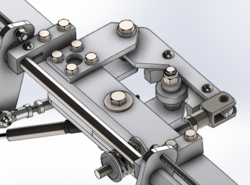
edmuss Posted June 2, 2022 Author Share Posted June 2, 2022 (edited) Best laid plans and all that! Finished the remaining detail drawings at 1am and realised that I had built a massive hard centre detent in, so promptly spent most of the night awak trying to figure out in my head how to best rearrange the cam setup. Redesigned the cam to be a seperate removeable milled block of delrin, being a dimensionally critical component it would be far better to get it profiled on the CNC mill than to try to do it by hand. If I find that I want to adjust the detent then I can get a new block milled. The cam profile is a little more like the MFG crosswinds, it's not quite linear but spring pull from one side to the other is only about 0.3mm different I also developed the mounts for the main spindle, another block of milled delrin with a keyhole slot that will clamp the Ø16mm stainless bar. Got the drawings to the CNC man who will be working on them as and when he can, spent most of this afternoon jigsawing, drilling and filing the arms to shape, some of the larger holes for the ball races I will need to do at work and ream them to size. Edited June 2, 2022 by edmuss 1 Ryzen7 7800X3D / RTX3080ti / 64GB DDR5 4800 / Varjo Aero / Leap Motion / Kinect Headtracking TM 28" Warthog Deltasim Hotas / DIY Pendular Rudders / DIY Cyclic Maglock Trimmer / DIY Abris / TM TX 599 evo wheel / TM T3PA pro / DIY 7+1+Sequential Shifter / DIY Handbrake / Cobra Clubman Seat Shoehorned into a 43" x 43" cupboard. Link to comment Share on other sites More sharing options...
edmuss Posted June 6, 2022 Author Share Posted June 6, 2022 All of the aluminium flats are now cut, drilled, tapped and machined. Bearings are fitted and main pedal frames assembled setting nice and freely on the main spindle. About 75% of the delrin parts are machined now, hopefully the rest will be finished tomorrow. 1 Ryzen7 7800X3D / RTX3080ti / 64GB DDR5 4800 / Varjo Aero / Leap Motion / Kinect Headtracking TM 28" Warthog Deltasim Hotas / DIY Pendular Rudders / DIY Cyclic Maglock Trimmer / DIY Abris / TM TX 599 evo wheel / TM T3PA pro / DIY 7+1+Sequential Shifter / DIY Handbrake / Cobra Clubman Seat Shoehorned into a 43" x 43" cupboard. Link to comment Share on other sites More sharing options...
edmuss Posted June 9, 2022 Author Share Posted June 9, 2022 Finished the main assembly and carried out the initial dry fit. Needed to add slots to the cam plate fixings so I can more easily align the centre detent and also reposition the lower connection points for the damper gas struts as they were limiting the stroke. With the spring tension wound off the dampers hold the pedals where they're left (for helo use), for anything else it's just a case of wind the spring preload collar on about 25mm and they return to centre with a nice slow damped motion Still waiting on the laser cut parts for the toebrakes but they will be useable without for now (got an M16 bolt in there which will act as the brake pedal spindle. All being well I will set up the main cross beam magnet and hall sensor tomorrow and get them bolted to the desk over the weekend. 1 Ryzen7 7800X3D / RTX3080ti / 64GB DDR5 4800 / Varjo Aero / Leap Motion / Kinect Headtracking TM 28" Warthog Deltasim Hotas / DIY Pendular Rudders / DIY Cyclic Maglock Trimmer / DIY Abris / TM TX 599 evo wheel / TM T3PA pro / DIY 7+1+Sequential Shifter / DIY Handbrake / Cobra Clubman Seat Shoehorned into a 43" x 43" cupboard. Link to comment Share on other sites More sharing options...
edmuss Posted June 10, 2022 Author Share Posted June 10, 2022 (edited) Having gotten the mechanical side of the linkages all straightened out and working correctly I set about setting up the magnet and hall sensor for the cross beam. Turns out that the magnets that I was intending to use weren't really strong enough or large enough to not move the sensor too far out of the magnetic field and sent the output heading back towards zero at full pedal deflection. As a backup I had already stripped a far larger, stronger magnet from an old HDD; this generated far better results so I set about figureing out how to best mount it. Made a small aluminium angle bracket that bolts onto the front face of the cross beam, I clamped the prewired sensor to the front of the chassis section with a plate. I cut a slot into the back of the plate to keep the sensor aligned correctly and it snugs up just nicely. Also got a couple of videos to show the operation: - Half spring tension https://photos.app.goo.gl/bXWBLPt8H5n9UBKR6 Full spring tension https://photos.app.goo.gl/Mjg6RuouGbyBTatHA Spring tension released for helos https://photos.app.goo.gl/623PBkMJt7moS9JE8 Edited June 10, 2022 by edmuss 2 Ryzen7 7800X3D / RTX3080ti / 64GB DDR5 4800 / Varjo Aero / Leap Motion / Kinect Headtracking TM 28" Warthog Deltasim Hotas / DIY Pendular Rudders / DIY Cyclic Maglock Trimmer / DIY Abris / TM TX 599 evo wheel / TM T3PA pro / DIY 7+1+Sequential Shifter / DIY Handbrake / Cobra Clubman Seat Shoehorned into a 43" x 43" cupboard. Link to comment Share on other sites More sharing options...
edmuss Posted June 11, 2022 Author Share Posted June 11, 2022 So the pedals are mounted to the desk, a bit of faffing to with the sensor height to get most consistent response from it and a quick test. Set as a pure straight line on the rudder axis of the ka50 it's stupendously sensitive yet incredibly accurate to go with it. Having a full 10 inches of pedal throw means that I can keep zero curve and still have the smallest inputs possible simply by flexing my toes, for gross rudder inputs I just slide my feet and it's completely predictable. I was able to circle strafe a train moving at 90kmh, 10m off the deck, transition into a side slip and then transition into reverse flight before resuming the circle strafe in the opposite direction. Such shenanigans were absolutely impossible with the old rudders The rudders are solid with no flex, even with resting the whole foot on them, no slop in the mechanism and instant response. Total cost to make them was about £60 but I did have the aluminum in stock and the CNC machining cost me the price of 6 bottles of cider. I'm very happy with how they've turned out, if anyone wants to make themselves a set, yell and I'll update the drawings and release them. 1 Ryzen7 7800X3D / RTX3080ti / 64GB DDR5 4800 / Varjo Aero / Leap Motion / Kinect Headtracking TM 28" Warthog Deltasim Hotas / DIY Pendular Rudders / DIY Cyclic Maglock Trimmer / DIY Abris / TM TX 599 evo wheel / TM T3PA pro / DIY 7+1+Sequential Shifter / DIY Handbrake / Cobra Clubman Seat Shoehorned into a 43" x 43" cupboard. Link to comment Share on other sites More sharing options...
Lobinjaevel Posted June 12, 2022 Share Posted June 12, 2022 They turned out great, excellent work! 1 Link to comment Share on other sites More sharing options...
Recommended Posts