

No1sonuk
-
Posts
1595 -
Joined
-
Last visited
Content Type
Profiles
Forums
Events
Posts posted by No1sonuk
-
-
Your code is doing exactly what you told it to because you are using the code lines for the BUTTON position, not the light.
DcsBios::LED pltGroundOverrideBtn(0x86f4,0x4000, 3); gives you the position of the button, so the light will go on and off when the button is pressed and released.
What you need is the ground override INDICATOR:Pilot Ground Override Indicator (green)AH-64D/PLT_GROUND_OVERRIDE_LDcsBios::LED pltGroundOverrideL(AH_64D_PLT_GROUND_OVERRIDE_L_AM, PIN);It's in the "PLT INTERNAL LIGHTS" group.
The Master Arm lights are there too... -
Someone else tried this about 18 months ago.
I don't know why he abandoned it.
I had a WiFi-connected ESP32/TFT running a CWP program, so it's VERY useful if it works well. -
On 6/22/2025 at 3:40 AM, Kenpilot said:
Thanks Bucic!
Unfortunately I'm not really sure how to answer your question or how I can help. Even after building my sim, I still feel like I'm a beginner when it comes to a lot of things associated with Arduinos. I'm not even sure what daisy-chained shift registers are lol Sorry I'm not much help, but there are plenty of others on here that are much more well versed on these things, I'm sure they'll be more than happy to help! Good luck in your build!
Shift registers, in this context, are a means of converting parallel data into serial.
They take the parallel data in and "shift" it out one bit at a time, or take 1 bit in at a time and shift it to parallel. They usually have a way of linking between devices so you can make a chain for more parallel connections than one device can provide.
The PISO variety take Parallel In and give Serial Out. You can use this to expand the number of inputs an Arduino can take OR you can use it to convey a large number of inputs through only a few wires - IIRC, this is how TM grips transfer their 20+ button data to the base using a 6 pin mini DIN connector.-
 1
1
-
-
The DCSBIOSBridge mentioned CAN do the job, but many people experience lag when using it. There's currently no dev for it, so it should really only be used for testing if all else fails.
Rapti's response is the way to go for normal running.
-
 1
1
-
-
4 hours ago, SrSosio said:
If you don't mind the high cost of them, you can try the HCMS-2973, which is the closest thing that I've seen to the real thing. There arent 7 digit boards though, so you'd need to hide one digit on each side, as the real thing seems to have 7+8+7 displays.
You can see the hidden digits at the edges of the slot in that image. They'd use all 8s - custom 7s would cost too much.
-
From the addresses.h file:
#define AH_64D_SEAT_POSITION 0x8750, 0x0100, 8So if you weren't giving it all 3 of those numbers, it won't work.
-
4 hours ago, Vinc_Vega said:
I would try to completely replace the onAcftNameChange function with a reading of your selector switch

Regards, Vinc
Did you know this was a thing?

I'm also going to look into creating a 2-seat version of the switch function.
-
1
-
-
On 6/5/2025 at 7:01 PM, akinilgun said:
Hello, I am trying to make a matrix with dcs bios for f16 icp. However, I could not get it to work. When I upload and run the code below, the icp's number 8 key is constantly pressed. I would be very happy if you could help me with the error. Thank you very much in advance.
Are you using blocking diodes in the matrix?
-
1 hour ago, Nightdare said:
I think it's rather insulting to charge such an amount and then still require your customers to source their own $40 power supply
It's possible that's a legal liability thing.
-
3 hours ago, agrasyuk said:
In the meantime, I'm using DCS UFC (which is now DCS UFX X) software on a tablet. It is usable, although the font started to flicker some versions back.
The old version still works (I use it), but there won't be new modules added. DCS UFC X is a newer pay per module version.
-
On 4/10/2025 at 6:15 PM, Jocman said:
Hi all.
I'm trying to develope a Freejoy controller for my cockpit and built a PCB.
I'm getting some problem, so I'm wondering if I'll post some description and PCB diagrams, is there anyone who could spent some time to help me to fix it (or at least try to)?
Thanks in advance
Start a separate thread in this forum and we'll see what we can do.
-
8 hours ago, Rapti said:
Unfortunately, changing the value did not help.
If anyone has a working sketch, I would be happy, as I unfortunately have no programming skills myself
What's your hardware setup?
-
It could be electrical noise. Try this:
The resistors shown dotted aren't necessary - DCS-BIOS turns on those in the Arduino.
-
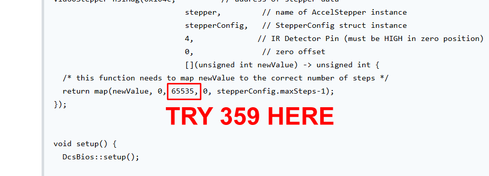
One problem you'll have is that the full rotation of the A-10 HSI is 0-65535, but the common data magnetic is 0-359.
It looks like the code you have is designed to work with 0-65535 input. Try changing the value shown below.
If that fails, try writing a stepper routine that takes a position number, and send it from a normal DCS-BIOS code block.
-
4 hours ago, Aronis said:
This kind of DIY is fun and not physically taxing, until you have to crawl onto the floor to reach behind the PC to plug in something LOL.
Build a stand...

-
As mentioned in Discord, which switches are they?
It sounds like you were drawing too much current and were lucky not to blow the Arduino's regulator or I/O pins.
The "bad burning smell" is the stage just before the smoke escapes!


-
OK. That should compile. What error message is it giving?
However, I'm not sure that code will do what you want.
There's nothing stopping the MASTER_CAUTION_RESET_SW toggling every loop while the button is down. -
How are you trying to do it?
The format is:sendDcsBiosMessage("MESSAGE", argument);
-
DCS-BIOS will natively work only with the ports ON the processor.
If you want to use more through multiplexers and expanders, you have to write all the code to handle that yourself, then use the sendDcsBiosMessage function in DCS-BIOS to send the switch signals to DCS.
You MIGHT be able to do it with a Nano using a matrix, but you're pushing it for that many inputs, AND remember that you CANNOT use pins D0 and D1 AT ALL with an Arduino running DCS-BIOS because they are used for the USB comms.
1 hour ago, CYPHER11 said:i really appreciate any kind of help. Also for future Projects it would also be cool to know if i want to use a Huge amount of LED´s with DCS BIOS, is the Multiplexer / MCP23017 the right choice? Do i need a complete different approach?
MAX7219 LED drivers are a popular choice. 64 LEDs from one device. They can make eight 7-segment (plus decimal point) numerical displays or an 8x8 matrix, and a few can be "daisy-chained" to save IO pins.
There's also the addressable LEDs - commonly called "Neopixels" after Adafruit's implementation of them.
-
1
-
-
It might be the routing of the wires as much as the length if it's noise.
-
1
-
-
Sounds like electrical noise on the wires.
Is the wire run to the Arduino long?
Try twisting all 3 wires together.
Another thing to try is a 100nF (or similar) capacitor between each Arduino input and GND.
-
1
-
-
It's really not that hard. I'll try to find a less patronising guide tomorrow.
-
OK. Get rid of that zip.
Go here : https://github.com/DCS-Skunkworks/dcs-bios/releases
and follow this:-
1
-
-
11 hours ago, Hammer1-1 said:
I got a Tek Creations AH-64D KU pad and Im trying to get the display exported to this device. Ive no idea where to even start; how would I go about doing this job? TIA
Try this:
https://tekcreations.slab.com/public/posts/dcsbios-installation-skunkworks-byjgzhpu


Spitfire Tachometer Gauge
in Home Cockpits
Posted
I initially thought it was like the P-51 ASI that has a non-linear gauge face, but looking at it, and the gauge script, it IS linear:
-- Tachometer
TachometerGauge            = CreateGauge()
TachometerGauge.arg_number = 37
TachometerGauge.input      = {0.0, 5000.0}
TachometerGauge.output     = {0.0, 0.5}
TachometerGauge.controller = controllers.TachometerGauge
This is how the gauge model reacts to the input number. On the Spitfire gauge above, there is only a start and stop, meaning the whole travel is linear.
It SHOULD be 0-65535 is the full travel of the gauge.
One thing I did see, though - Remove this, and all the other serial lines:
Serial.begin(115200); // Starter seriel monitorIt can disrupt the USB communications with DCS.
If you want to output data while running a game for testing, use an I2C-connected character LCD or other display that doesn't use the USB connection.