overpro
-
Posts
158 -
Joined
-
Last visited
-
an Arduino USB HID controller, composite USB controller
overpro replied to overpro's topic in Home Cockpits
Hi Oresther, I don't think the code hardcoded the controller name to "Controller" Please can you let me know where you changed the code and also provide a screen shot indicate the issue you encountered? Thanks -
my friend has the exact same issue, he uses the steam version and checked the local file cache in steam and no error detected, still no luck. Is there any updates on this issue? Thanks
-
Hi MetalGear, Just wondering if you have resolved this issue, I'm asking because my friend encountered the same issue, he uses win7, TM Hotas Warthog, and just upgraded DCSW to 1.5. Regards
-
an Arduino USB HID controller, composite USB controller
overpro replied to overpro's topic in Home Cockpits
Is it DCSW A10C or something else? if the game only recognize the edge triggered signals instead of level triggered signal then the arduino code need some rework. the current arduino code only works as level triggered:flip to On always make the button as On. There are other types such as rising edge triggered: flip from off to on will generate a Button On pulse, falling edge triggered: flip from on to off will generate a Button On pulse, rising/falling edge triggered: flip from off to on or on to off will both generate a pulse. Refer to post #99 to rewrite the button logic if you want to implement edge triggered type. http://forums.eagle.ru/showpost.php?p=2299483&postcount=99 I 'm confused on the last question, I think we are talking about the joystick right now. So what do you mean by “using this toggle switch with Joystick”? -
an Arduino USB HID controller, composite USB controller
overpro replied to overpro's topic in Home Cockpits
can you please post a picture of the wiring design? by using http://fritzing.org/ or whatever tools you prefer -
an Arduino USB HID controller, composite USB controller
overpro replied to overpro's topic in Home Cockpits
This is not weird because my implementation in the arduino code, the column pins ( 38~54) are configured as input with pull up resistor enabled, that's say if it's not connected to anything else the pin is in HIGH state (+5V) by default, So if the switch is in the off position, the column pin 39 is in +5V state, the small light bulb is on. If you flip to On position, the pin 39 is in LOW state, the light goes off. -
an Arduino USB HID controller, composite USB controller
overpro replied to overpro's topic in Home Cockpits
Well, this image give me an impression that you are using the arduino code which implemented 8 OnOffOn toggle switch algorithm, the OnOffOn toggle switch off position is also a "On" in my implementation, so there are 8 button's lit, which is correct. which arduino code are you using? is it the one from my first post or is it the one from post 150? http://forums.eagle.ru/showpost.php?p=2524345&postcount=150 -
an Arduino USB HID controller, composite USB controller
overpro replied to overpro's topic in Home Cockpits
Got it, the windows control panel can only show 32 buttons which are all occupied by rotary encoders on 1st HID controller, so you have to use something else for testing, like this one: http://www.planetpointy.co.uk/?dl_id=5 Regarding change the joystick name, as you have installed a Ubuntu 14.04 VM, please try compile the firmware first, by following this procedures on my first post: --------------------------------- Firmware compilation instruction --------------------------------- If the compilation success, you can change the name by editing Descriptor.c and change ProductString struct's UnicodeString member: const USB_Descriptor_String_t PROGMEM ProductString = { .Header = {.Size = USB_STRING_LEN(14), .Type = DTYPE_String}, .UnicodeString = L"C.V.P Joystick" //change the string at here, // note that the you need to change .Size number accordingly }; -
an Arduino USB HID controller, composite USB controller
overpro replied to overpro's topic in Home Cockpits
which program did you used for testing the button? -
an Arduino USB HID controller, composite USB controller
overpro replied to overpro's topic in Home Cockpits
Yes, it's possible, you might want to check the arduino and the atmega16u2 firmware source code first. -
an Arduino USB HID controller, composite USB controller
overpro replied to overpro's topic in Home Cockpits
Unfortunately, the atmega series doesn't have unique identifier in the chip. I'm thinking to read the SN from EEPROM, so people can use FLIP to change their own SN stored in EEPROM. -
an Arduino USB HID controller, composite USB controller
overpro replied to overpro's topic in Home Cockpits
You are correct, the Serial number should NOT be hardcoded, let me check if Atmega16u2 has some sort of build in serial number in the chip. -
an Arduino USB HID controller, composite USB controller
overpro replied to overpro's topic in Home Cockpits
Please check post #150. I added an attachment there. -
an Arduino USB HID controller, composite USB controller
overpro replied to overpro's topic in Home Cockpits
Actually I have finished this part but I haven't push the arduino/firmware code to github yet, because this change might affect some people's cockpit. It's not using row 4,5 but row 15 instead ( pin 37 ) as the OnOffOn toggle switch, so you can connect 8 toggle switches. Connect the middle pin on the switch to row15 ( pin37 ) and 2 other pins to col0/1 col2/3 ... col14/15. The 8 OnOffOn switch will occupy 24 button bits in the HID report ( 8 switches * 3 bit per switch ). As 16 pins are used and 24bit data generated, it must borrow one byte from the normal buttons, so col 8~ 15 on row 14 will be used for the OnOffOn button. Don't connect any switches to this section. Now the normal button count is 16 * 10 + 8 = 168, which used 168 bits 8 OnOffOn switches used 24 bits, 32 rotary encoders used 64 bits. If you want to have some test I can provide a dedicated arduino/firmware here. http://forums.eagle.ru/attachment.php?attachmentid=125192&stc=1&d=1445303177 This is definitely possible, let me get a uno board first. CVP_JoystickController.ino.zip -
an Arduino USB HID controller, composite USB controller
overpro replied to overpro's topic in Home Cockpits
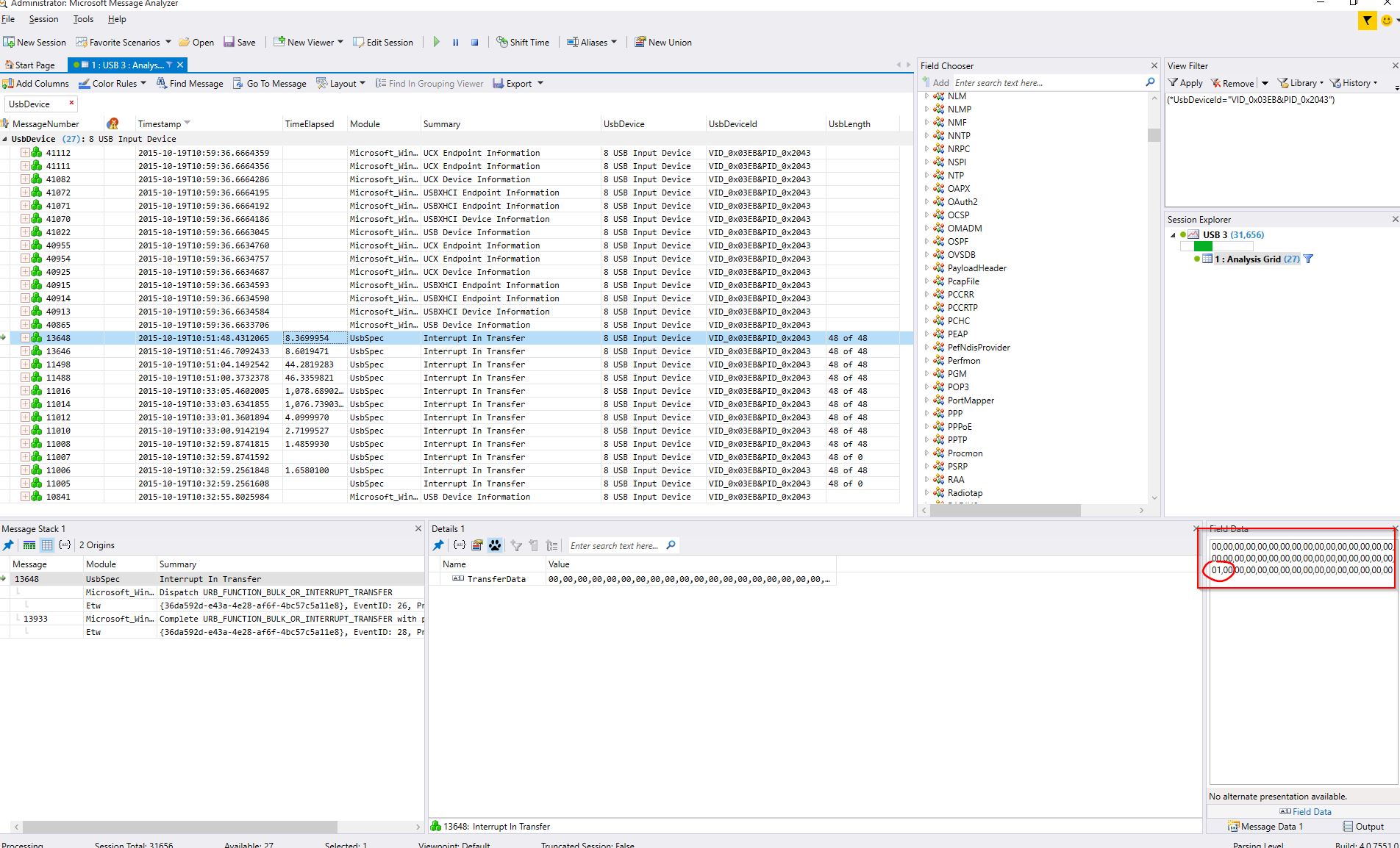
Hi Chakko, I suspect SV Mapper doesn't recognize the button press correctly, I used Microsoft Message Analyzer - MMA to capture the USb device HID packages and I can see the HID report is correct. Attached is the screen capture, the lower right window is the HID Input report, as you can see we have 48 bytes, the first 16 bytes are the 8 axis, the 17~32 bytes are the button value for Pin 22~29, the 33~48 bytes are the button value for Pin 30~37. I shortcut the pin30 and pin38, so byte 33's value is 0x01. And all else are 0 which means no button were pressed. I'm thinking it might be better to test it under FSUIPC directly. Or you can use MMA to test your button directly. Please watch the 2 video tutorial first, the MMA GUI is not that straightforward as I expected. https://msdn.microsoft.com/en-us/library/windows/hardware/dn741264%28v=vs.85%29.aspx