Ulukaii
-
Posts
19 -
Joined
-
Last visited
Content Type
Profiles
Forums
Events
Everything posted by Ulukaii
-
Has anyone tried SFX-100 ?
-
Hi @Feathers For the export of the Winwing screens, simply use the SimAppPro software. Then, if you have addtional screens, you can copy-paste the .lua file that SimAppPro creates and add your own exports to it. No need to run Helios at all. Check out A Hornets Nest on Youtube for a detailed guide
-
i can confirm the issue for backlighting on my MIP
-
Massive stutters, especially in MP close to objects
Ulukaii replied to Ulukaii's topic in Game Performance Bugs
Holy smokes. To my surprise, switching from bin-mt to bin and NOT running as administrator led to 2hrs of smooth gameplay. Will try again later and if stable, mark as resolved. Earth seems to be a globe after all -
Massive stutters, especially in MP close to objects
Ulukaii replied to Ulukaii's topic in Game Performance Bugs
@sleighzy all other sources that I read recommended to run it as admin .... -
Massive stutters, especially in MP close to objects
Ulukaii replied to Ulukaii's topic in Game Performance Bugs
Small stutters in Single Player, massive stutters in multiplayer. I will try the not running as admin and bin-mt change to bin. All others have been extensively tested. -
My DCS installation is suffering from massive stutters coming from CPU and I can't pinpoint the issue ... any recommendations appreciated! Situation PC is an AMD Ryzen 7600 X3D with 96GB RAM and GeForce 5080 PC is literally used only for DCS, ultra-fresh Win11 installation, DCS + plugins, few tools (Notepad++) nothing else My DCS setup is moderately complex with following plugins used: SimAppPro and full Winwing MIP DCS-BIOS for my simpit panels TrackIR In multiplayer, SRS Problem Description Many micro stutters and massive stutters in MP, especially when close to other objects (e.g. cold and dark on a carrier. ) Inbetween the stutters, if i do not limit FPS, theoretical FPS is 200+ . See Logfiles attached and video here: What I tried to solve the problem Tried to solve the problem on multiple levels: BIOS, Windows, DCS. From the video above, it seems to be 'CPU-related so here is what I tried so far: BIOS SMT off or on EXPO settings on, off etc Windows Pagefile Process Lasso Unpark CPUs DCS Followed https://www.youtube.com/watch?v=zKLp8QTwyDA Most graphics settings to low Next steps Pretty much exhausted, next step will be full win reinstallation unless someone can see the problem from the logs or video ... thanks! dcs.log
-
Wanted to post this as a quick tip. Situation: you are in DCS, Winwing MIPs operating normally. Then you Alt-Tab out of the game and Alt-Tab back into the game. Problem: MFD screens are lost. In Windows display settings, the layout is messed up. Solution: Make sure to have the MFD screens connected to adjacent ports on the USB hub. Thanks to @X-31_VECTOR for the hint.
-
Hi @Gremlin77 1) If you want a close to OH-spec fit of your Winwing UFC and MFDs, check out my Winwing Mod here: https://makerworld.com/de/models/650441-v2-openhornet-mod-for-winwing-integration 2) For your surplus PCBs, I think there are some members over at the OH Discord who have been waiting for a group buy for a long time and would be very happy to buy a full set or whatever you have. If you put them into the marketplace-thread over there, they''ll see it: https://discord.com/channels/392833351238811648/1092859380623474809 Happy building! I am building with my son, too:-) Ulu
-
F16 Cockpit lighting sync with game via DCS Bios
Ulukaii replied to mikez69's topic in Home Cockpits
Here is an example code for the READ FROM DCS command, if you want to use DCS BIOS: //Check Arduino board in use #if defined(__AVR_ATmega328P__) || defined(__AVR_ATmega2560__) #define DCSBIOS_IRQ_SERIAL #else #define DCSBIOS_DEFAULT_SERIAL #endif #ifdef __AVR__ #include <avr/power.h> #endif //Include required external libraries #include "DcsBios.h" #include <Adafruit_NeoPixel.h> //Set up the backlight (BL) channels; original OpenHornet code has 10 different channels. const uint8_t UIP_BL_CH1 = 11; //Arduino control Pin const uint8_t UIP_BL_CH1_COUNT = 208; //number of individually adressable LEDs Adafruit_NeoPixel UIP_1 = Adafruit_NeoPixel(UIP_BL_CH1_COUNT, UIP_BL_CH1, NEO_GRB + NEO_KHZ800); //instantiate LED strip object //set up LED colours uint32_t IndYellow = LC_1.Color(255, 255, 0); //Yellow Indicators uint32_t IndRed = LC_1.Color(255, 0, 0); //Red Indicators uint32_t IndGreen = LC_1.Color(0, 255, 0); //Green Indicators uint32_t IndWhite = LC_1.Color(40, 40, 30); //White for Jett Station Select toggle light uint32_t dark = LC_1.Color(0, 0, 0); //No colour //Define a function that takes the INSTR LT value from DCS and sets the hardware LEDs accordingly void onInstrIntLtChange(unsigned int newValueInstrIntLt) { uint8_t brightness = map(newValueInstrIntLt, 0, 65535, 0, 255); //Instrument brightness according to value in DCS uint32_t PanelGreen = LC_1.Color(0, 100 * brightness / 255, 0); //Panel backlight colour //MASTER ARM panel backlight for (int i = 4; i < 25; i++) { UIP_1.setPixelColor(i, PanelGreen); } //HUD panel backlight for (int i = 59; i < 115; i++) { UIP_1.setPixelColor(i, PanelGreen); } //SPIN RECOVERY panel backlight for (int i = 145; i < 174; i++) { //SPIN RECOVERY panel backlight 1/3 UIP_1.setPixelColor(i, PanelGreen); } for (int i = 175; i < 181; i++) { //SPIN RECOVERY panel backlight 2/3 UIP_1.setPixelColor(i, PanelGreen); } for (int i = 182; i < 208; i++) { //SPIN RECOVERY panel backlight 3/3 UIP_1.setPixelColor(i, PanelGreen); } //... add more panels here .... UIP_1.show(); } //Most important line coming up: //This "integer buffer" command actually links the hardware-controlling function defined above to the specific event that the instrument light has changed in the DCS software. DcsBios::IntegerBuffer instrIntLtBuffer(0x7560, 0xffff, 0, onInstrIntLtChange); void setup() { //Run DCS Bios setup function DcsBios::setup(); // INITIALIZE NeoPixel strip object (REQUIRED) UIP_1.begin(); // Show the neopixel UIP_1.show(); } void loop() { //Run DCS Bios loop function DcsBios::loop(); } And the code to set the value in DCS by reading from a a potentiometer (or, in my case, a rotary encoder) could be as simple as DcsBios::RotaryEncoder instPnlDimmer("INST_PNL_DIMMER", "-3200", "+3200", PIN_A, PIN_B); (please refer to DCS BIOS library) -
F16 Cockpit lighting sync with game via DCS Bios
Ulukaii replied to mikez69's topic in Home Cockpits
Take inspiration from OpenHornet. To set the desired light value, the following route is used: Potentiometer --> Arduino --> DCS-Bios --> set INSTR Lt value in DCS. To read the light value from DCS, the following route is used: DCS --> DCS-Bios --> Arduino (a different one that controls the LEDs) --> LEDs. When I now turn the potentiometer, the desired LED brightness value is sent to DCS; and with no noticable delay, it is read from DCS and the real-life LEDs are set accordingly. Works flawlessly. Video attached. IMG_3404.mov -
Sold.
-
Selling a Winwing Orion 2. Location: Germany. Asking 120 or best offer. Only selling because it doesnt fit into my home pit side consome and I had to change it with a Gemini

-
I have Winwing and DCS Bios running in parallel on a regular basis without issues. DCS Bios is supplying 5 COM ports at the moment. Recommendation: make sure that the Winwing line in your export.lua comes after the DCS Bios line, just in case.
-
Received my Moza FFB base a few days ago and I am very unhappy with the product. Before returning, a few questions. 1. Around the center, there is a "no force zone" of a few cm in any direction. Feels super cheap. 2. Pitching up, at around 1/3 of the travel, there is a noticeable hardware detent. Is my stick defective? I tried this in many different profiles (F-18, F-16) and it is always the same, so it feels hardware related. See Video attached! 3. When working "against the force", beyond a certain point, it feels as if the stick is just "giving up" and reducing forces again. Is this normal? 4. Sometimes the stick starts vibrating / moving even though there is no game going on. Is this normal? Looks VERY defective to me. IMG_3664.mov
-
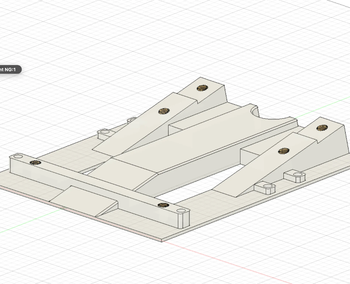
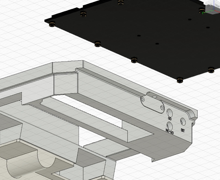
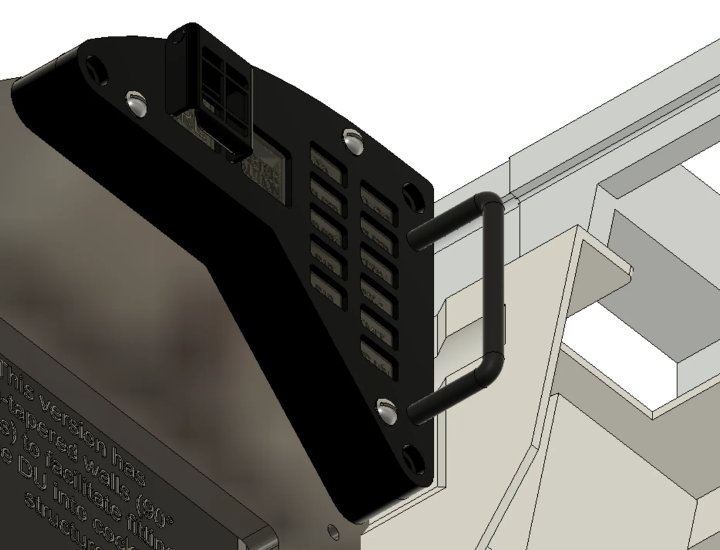
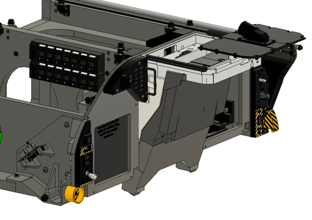
Here is a 3D-printable set of parts that I have designed that allow you to integrate your Winwing MIP into the OpenHornet upper and lower instrument panel (UIP and LIP). I hope they are useful for some of you and also I would appreciate any feedback, as I hope to be able to contribute this to the official OH as a mod soon. Download link: https://makerworld.com/de/models/650441 You can also view further developments on my Github (make sure to use the develop branch) and follow my build log on the OpenHornet Discord server. Also make sure to check out other concepts like the fully 3D-printable panel in this forum or Nick's Winwing OpenHornet integration in this Facebook group, which has a slightly differentv concept. Background / Summary / Status My idea was that I want to have a high-fidelity cockpit as provided by the OpenHornet plans, but want to accelerate my build and make it playable early on with the help of some Winwing components…. while adding more panels step by step later on. I wanted to do a full Winwing MIP integration, including the HUD panel. Status: This is version 2 of my integration. I have already built it IRL and optimized the fittings. I think the quality is already very good and you can directly start printing the parts and it should work. If you encounter any issues, I'd appreciate your feedback. Feature overview The parts in my design are constructed with 3D printability in mind. Only the face plate is recommended to be cut from an acrylic sheet, due to its size. The integration positions the Winwing UFC and HUD panels as closely as possible to the real Hornet. However, to integrate the Winwing MIP into OpenHornet, several design choices have to be taken. This is due to the fact that the Winwing MFD bezels are larger and that the Winwing HUD panel comes with the HDG and CRS knobs directly attached to it. The existing solutions by the community follow different design choices. See a comparison at the bottom of this post to help you choose between the concepts. Construction features include: The main holding bracket is firmly secured using M5 screws and six heat inserts: The BIT box is open on the lower side to allow for (some) access to the buttons on the upper side of the Winwing UFC: The back cover of the UFC panel is tapered, allowing space for the eyebrow panels: Comparison of different integrations:
-
Reporting back on how things developed. Winwing asked me to open the screen case, destroy the screen and send photos so they can send a replacement device. Upon screen / case disassembly, I discovered that an internal cable connecting the PCB to the screen was not properly locked into the connector. I carefully inserted it into the connector and locked it. And the screen then worked again. I asked Winwing if my warranty would still be preserved and they confirmed this. So all OK in the end of the day.
-
Dear @WINWING team: thanks for your reply. While I am looking forward to have my individual case resolved, I am still a bit concerned that things only moved after I made this public via this forum. Nevertheless, I'll report here how it went. Kind regards Ulu
-
One of my three Winwing MFD screens is defective. It is only 5 months old so it is fully in warranty. The symptom is a "whiteout" effect. I sent a video to Winwing customer support showing the defect. From the video it immediately becomes quite clear that the defect is in the screen itself, not the driver, not the USB cable, even not the internal USB workings (as the LED on the backside confirms positive USB 4 connection). Long story short: The Winwing customer support kept stalling me and stalling me over the course of multiple days. E.g., they kept asking to do another video and then another ... and then saying "I need to talk to the tech team" or "I need to talk to the manager" My expectation would have been that they send out a new screen after having me confirm maybe once that cables etc. are all good. It is really a sad story because I generally like Winwings products and what they are providing to the flight sim community. But it seems to me they are not interested in providing after-sales support of their customers. Until today, they did not confirm to me that they are going to send out a new screen. I have recorded the customer service conversation and can provide proof to anyone interested.