slimheli
-
Posts
22 -
Joined
-
Last visited
Content Type
Profiles
Forums
Events
Everything posted by slimheli
-
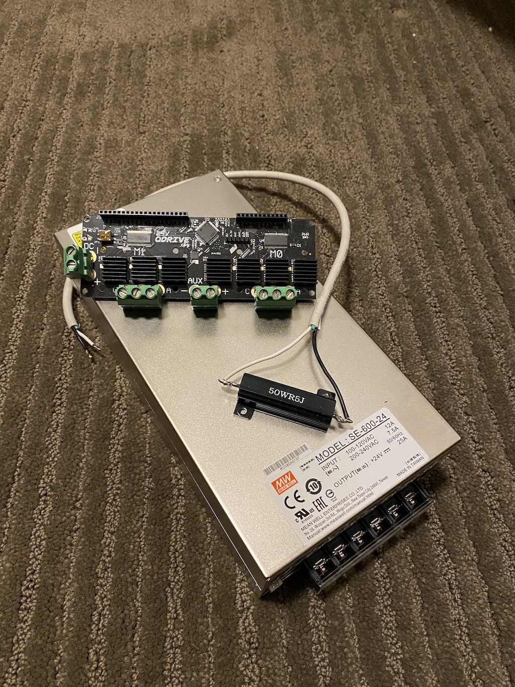
I printed and assembled 90% of this open source project but have just run out of time in life and I feel immense guilt whenever I see this sitting in the corner. Therefore I've decided to sell it to someone who can take it across the finish line. Included is the following: A 3D printed enclosure complete with bearings, pulleys, etc. I had ordered the wrong belts so those need to be purchased. 24V ODrive 3.6 board with brake resistor 2x D5065 270kv motors (already mounted into the enclosure) Mean Well 24V/25A power supply Located in Canada. There is probably $600 USDnull worth of parts here. I'll let it all go for $400 USD (you pay shipping).

-
Honey, I developed FFB joystick (DIY)
slimheli replied to propeler's topic in PC Hardware and Related Software
Hopefully this isn't a thread hijack but I feel like this is a very niche subject and would probably be buried in the "For Sale" section of the forums. So I'll roll the dice and give this a shot. If this is bad form, please let me know and I'll humbly remove my post. I printed and assembled 90% of the open source project but have just run out of time in life and I feel immense guilt whenever I see this sitting in the corner. Therefore I've decided to sell it to someone who can take it across the finish line. Included is the following: A 3D printed enclosure complete with bearings, pulleys, etc. I had ordered the wrong belts so those need to be purchased. 24V ODrive 3.6 board with brake resistor 2x D5065 270kv motors (already mounted into the enclosure) Mean Well 24V/25A power supply Located in Canada. There is probably $600 USD worth of parts here. I'll let it all go for $400 USD (you pay shipping). Huge shoutout to everyone here who has worked on this project. It's be a game changer.
-
Honey, I developed FFB joystick (DIY)
slimheli replied to propeler's topic in PC Hardware and Related Software
I've been busy! Need to order some pulleys and belts. Looking forward to actually firing this thing up.
-
Honey, I developed FFB joystick (DIY)
slimheli replied to propeler's topic in PC Hardware and Related Software
I just ordered the bolts that @TomVR suggested. I haven't started any final assembly, so I'll post how it goes. I printed almost everything in PETG witih 100% infill. So I think it'll be pretty strong. My intention is to take this beyond just FFB. I'd like to be able to program a helicopter autopilot that can be fed with DCS, X-Plane, or maybe even MSFS. -
Honey, I developed FFB joystick (DIY)
slimheli replied to propeler's topic in PC Hardware and Related Software
Wow. This looks amazing! What material and thickness did you specify for the metal bits? -
Honey, I developed FFB joystick (DIY)
slimheli replied to propeler's topic in PC Hardware and Related Software
Hey @TomVR, did you see my question regarding the f3d file you posted? It doesn't seem to want to open in Fusion. Any idea what was causing that? I'd like to try printing your case, and maybe adapt it for the ODrive motors I have. -
Honey, I developed FFB joystick (DIY)
slimheli replied to propeler's topic in PC Hardware and Related Software
Hey @TomVR, I'm not able to open the files in your github in Fusion. Just says it's not a valid zip file. Any ideas for me? -
Honey, I developed FFB joystick (DIY)
slimheli replied to propeler's topic in PC Hardware and Related Software
I purchased the 8192 cpr encoder that the ODrive shop recommended. https://odriverobotics.com/shop/cui-amt-102 -
Honey, I developed FFB joystick (DIY)
slimheli replied to propeler's topic in PC Hardware and Related Software
Okay. So I just want to summarize where things are at here. @walmis is working on building a kit that is basically a full re-design of @propeler's original design. I've been working on my own FFB design using ODrive and the MS FFB gimbal as inspiration for way too long and the designs I'm seeing here blow mine out of the water. So if I wanted to try building this, which repository would hold the best CAD's for me? Walmis' repository just has a STEP file for the box. Propeler's repository has the first version of his design, but it looks like he moved way past that with the latest iteration. Anyone have some input as to where to begin? I already have an ODrive and two of the D5065 motors with a good power supply. And I've got a 3D printer. Thanks for all the effort you guys have put into this! -
Open Source Joystick FFB / DIY FFB Joystick
slimheli replied to Berniyh's topic in PC Hardware and Related Software
Hey all, Wow, I just finally read through this entire thread. Pretty excited to see that others have been wrestling with the same challenges I've had for the past year or so. I'm currently part of a maker-space that includes some pretty phenomenal equipment, which includes some commercial grade 3D printers that can print in all kinds of material at insane resolutions. It's not cheap to print parts in these things, but I am certainly willing to get something printed to help you guys out. For myself, I'm building a helicopter sim and am interested in using FFB to simulate Force Trim Release. Let me know if I can help you guys out. Slim -
Sorry to flood this thread. I just thought I'd add one quick thing regarding the centering and the MicroHeli cyclic. You can adjust the spring force on the MicroHeli cyclic. The centering force is there, but it's extremely gentle. For my purposes (until that FTR module comes out), I'll gladly put up with it. My pit is torn apart right now, but I'll post what his controls look like in my set up when I get a chance.
-
Hey Trip, Thanks for the kind words. Sorry to hear your career change fell through. It's an insanely difficult industry to get into. I count myself extremely blessed. Anyhow, on to your questions: When the Force Trim Button is held the cyclic has no resistance at all other than the hydraulic resistance which is very light. However, most helicopters with a FTR system also have Cyclic Friction knobs that can be used to adjust residual friction to the pilot's preference. Some guys like it uber light, some guys (usually the heavy handed ones) like a bit more force. I'm of the opinion that it should be light because it forces you to relax and not over control (but that's just me). But in terms of measuring force, let's just say that the weight of the cyclic itself could cause full deflection if you weren't having to hold that button in. Guys who like to turn FTR off are usually doing flying with a lot of events (take offs and landings). Guys who are in the IFR realm typically leave Force Trim on as it allows them to multi-task a bit more with the hands (flipping approach charts, etc.). Not all helicopters have the option for Force Trim. The system adds weight, and weight is the biggest enemy of any helicopter. They cost huge $$$ to run, and customers frequently want to load the bird up with everything possible to make things as cost effective as possible. Often light/intermediate single engine utility helicopters do not have any trim system at all. So the pilot has to keep his hands on the controls, or awkwardly pinch the cyclic between his legs (not recommended). As far as resetting to center, I'd say the feature isn't necessary. If you want realism, then setting the cyclic to approximate center yourself should be required. The only time I've seen this feature is on $30 million Level D simulators. But that's an entirely different universe that has always blown my mind.
-
Hi there guys, I feel inclined to weigh in here a bit. I'm a commercial helicopter pilot, have flown everything from Hughes 300, 206, S-76, AW-139, BK-117, etc. No helicopter out there has a self-centering cyclic. The loads are too dynamic. However, different types of helicopters have different setups within the cyclic that may return the stick to a center that you as the pilot set. The most simple would be the 206. There are no springs whatsoever. If you as pilots let go of the cyclic, it will flop to one side and cause a lot of damage, particularly at low rotor rpm. As someone said before, when the machine is off, it's hydrostatic lock that keeps the cyclic where you left it. You can push against it and manually move it when the machine is off, but it's quite stiff. Next in complexity would be the Hughes 300, 500, BK117, MD902, etc. all use a similar setup. The cyclic is connected to linkage that includes a centering spring that is connected to a linear actuator. Using the trim hat will cause the linear actuator to physically move the centering spring itself. So it's effectively moving your center around. If you push against the cyclic, it will push against the centering spring. Releasing the cyclic will cause it to return to the center you set with the trim motors. The center changes from forward flight to hovering, and with every little power change you make due to all the wonderful aerodynamic forces in play with helicopters. For example, as you approach from forward flight to hover the right side of a BK will start to drop, so you're trimming left. As you come through translational lift the center moves back so you are trimming back. If you are hovering in to wind with the cyclic centered and pedal 90 degrees to the right, you'll have to trim left to keep centered. In the bigger machines with actual Force Trim Release, the cyclic is connected to magnetic brakes and linear actuators. The magnetic brakes all you to push against them which feels like a spring. But when you push the FTR, the mag brake releases which allows you to move the cyclic around with absolutely no centering force whatsoever. Releasing the FTR button re-engages the mag brake. Using the trim hat activates linear actuators which will move the entire assembly around (some exceptions apply in various models of the S-76). Yogi, I'm one of your customers. I've finally gotten around to hooking my controls up. I haven't flown them yet. But so far I'm really impressed with the quality of them. Feel free to throw any questions my way. I have a ton of training manuals and documentation if people are interested.
-
Does the cyclic stick stay in position when you leave it? Or do the springs cause it to return to center?
-
Question about building a collective
slimheli replied to slimheli's topic in PC Hardware and Related Software
Thanks for the quick response Hannibal. I've seen your stuff before. It looks great. Where did you get that clamp on the end of the collective lever? -
Hey all, For those of you who have built your own collective, what method are you using to pivot the collective lever itself? Obviously the axle that the lever pivots on needs to fixed so that it rotates when the collective lever is raised or lowered. Sorry if the question isn't clear. I'm not great a mechanic speak. Cheers!
-
Hey all, I have a terrible feeling that my Joystick just kicked the bucket. I've done every troubleshooting step multiple times listed on the Thrustmaster website, and on other websites. The joystick basically won't wake up from it's boot state. I checked and rechecked the connections and I'm nervous that at one point I might have mounted the joystick upside down (yes, I feel extremely stupid to even type that but I figure honesty is the best policy). All the pins are fine though, I know enough to never force anything. But in the off-chance that I've fried the board in there, does anyone have any clue what I'm going to have to go through to get this working again? Thanks for the input. slimheli
-
I am also interested in gauges. Please keep me posted when it's time to order!
-
Thanks Deadman! Yeah, I know you've offered before. I've been so dang busy for the past six months with getting married and all. Things are starting to settle down now so I have some decent time to put towards it. Thanks for the links on those instruments! I'll do some more research.
-
Well now I'm just giddy with delight! I shall wait eagerly kind sir.
-
Hey All, Thanks for the advice. I've been spending a ton of time trying to figure out what is going to be best for the MIP (mostly the Artificial Horizon, HSI, Altimeter, VSI, and ASI). The fact that these are military spec sure don't make it easy. Part of me figures I could use SimKits instruments for the VSI and Altimeter and ASI. Any thoughts on that? Other than that, if anyone has these instruments actually working, I am sure I could pay some cash to have them replicate their instruments. Possible? Yes, I'm well aware that I am in far over my head as far as fabrication goes. I learned my lesson real early when I was trying to see how the Warthog Throttles fit into the side console. The result was me cutting it. Even though it does fit, I realized that the end result wasn't pretty and could have been done waaaaay better. Anyhow, that sort of stopped me in my tracks as far as the power tools go. :S However, I do happen to have some very handy friends who have access with CNC's and plasma cutters. I figure that I'll let those who know what they are doing do things best. I've been playing in Sketch Up a lot to try and learn some drafting. It's a ton of fun! As far as the A model MIP, are the dimensions actually the same as the C model? I've heard that it's a touch wider to accommodate the MFDs. Thanks for the input guys! Oh, btw, I'm located in Calgary, AB.
-
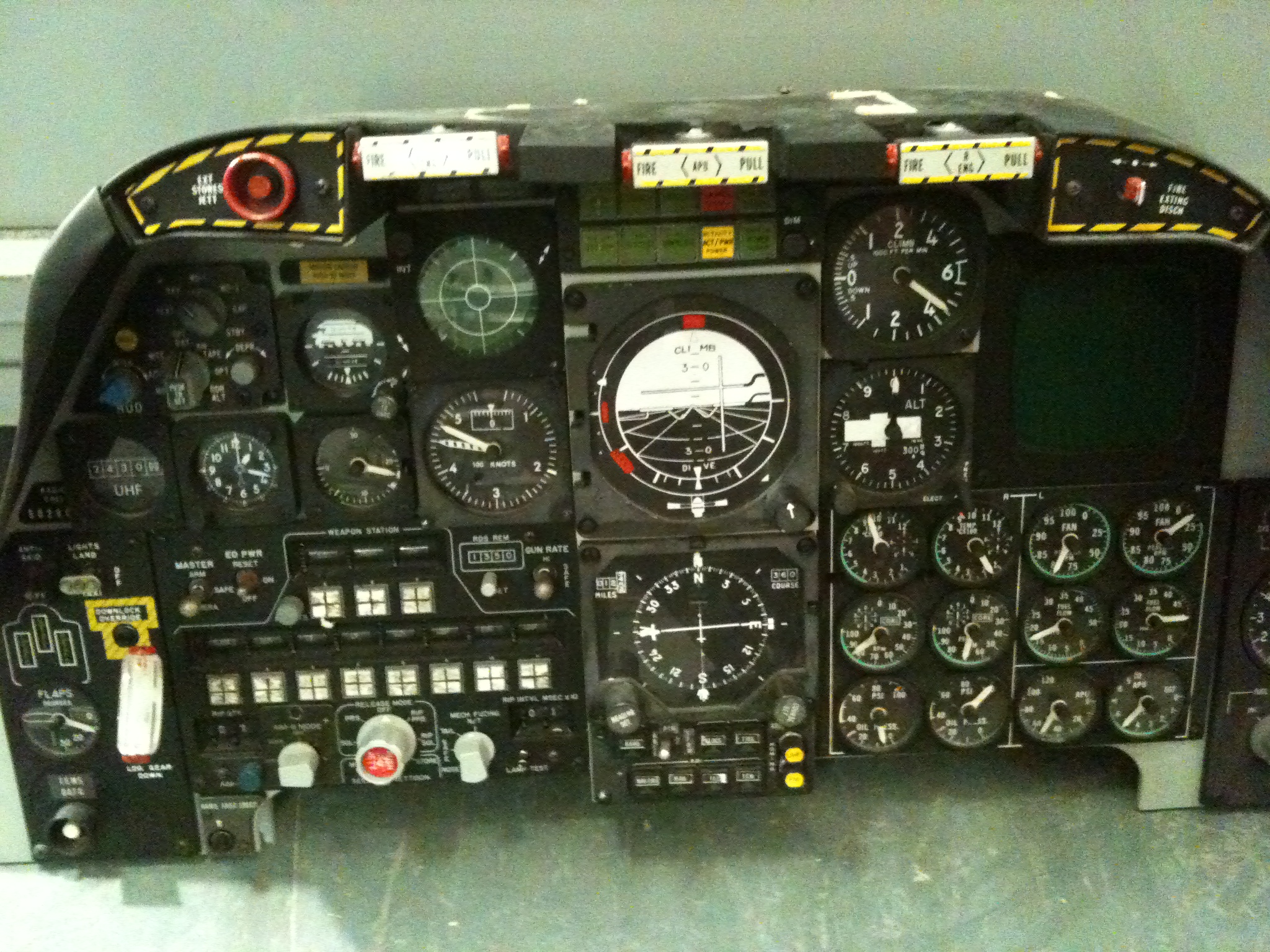
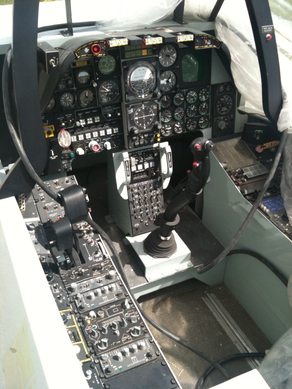
I happened upon a Situational Awareness Trainer for an A-10A. The owner said I could turn it into a sim and he would pay for all the supplies. Attached is a pic of the center panel. I have a hunch that I'm better off putting in the work to make this an A-10C as the old-style weapons systems will require an incredible amount of sorting around. Budget is not an issue with this project. Limited time and experience will using my hands is more the issue. I have a good handle on programming and technology, but I'm all thumbs when it comes to modifying and so forth. I'm trying to sort out how best to simulate the instruments, I'm pretty sure it's going to be best to use an LCD screen for the engine instruments, but the NAV instruments...?? not so sure. Thoughts?