LOGICNC.COM
-
Posts
54 -
Joined
-
Last visited
Content Type
Profiles
Forums
Events
Everything posted by LOGICNC.COM
-
I'm kinda stuck between a rock and a hard place right now. I really need a more capable machine to produce more than a couple units. I have purchased a larger milling machine, and am also working on a CNC plasma cutter to handle the steel parts... which right now take hours on the small mill I currently have. The problem I have right now is mostly financial...I currently don't have the funds to finish the CNC conversion of the larger mill and I also can't get the CNC plasma 100% functional yet. I made the mistake of going too cheap on the plasma cutter (direct from China Cut50D for about $300) and it puts out plenty of EMF interference which causes lots of issues with the computer/stepper motors on the CNC table. A brand name unit which would eliminate these issues is approaching $2k...something I just can't afford right now. By the way, the Cut50D actually works quite well for hand cutting...unfortunately it doesn't play well with CNC equipment. I am working through some shielding/grounding issues which I hope may still allow the use of this plasma unit for CNC.
-
Some of the Chinese machines aren't bad....they aren't great, but not bad. I started with a converted 47158 micro mill (Sieg X1) from harbor freight. With about $500 of electronics and a bit of work I had a fairly capable mill, which would even do steel (barely)...great for aluminum and acrylic though. This one is similar: http://littlemachineshop.com/products/product_view.php?ProductID=4660&category=1387807683 Add stepper motors, driver board, power supply and some hardware and you've got a fairly capable hobby machine.
-
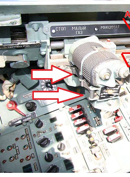
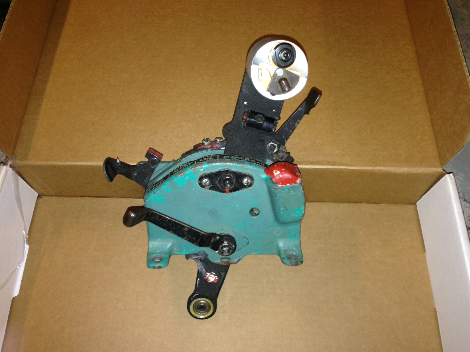
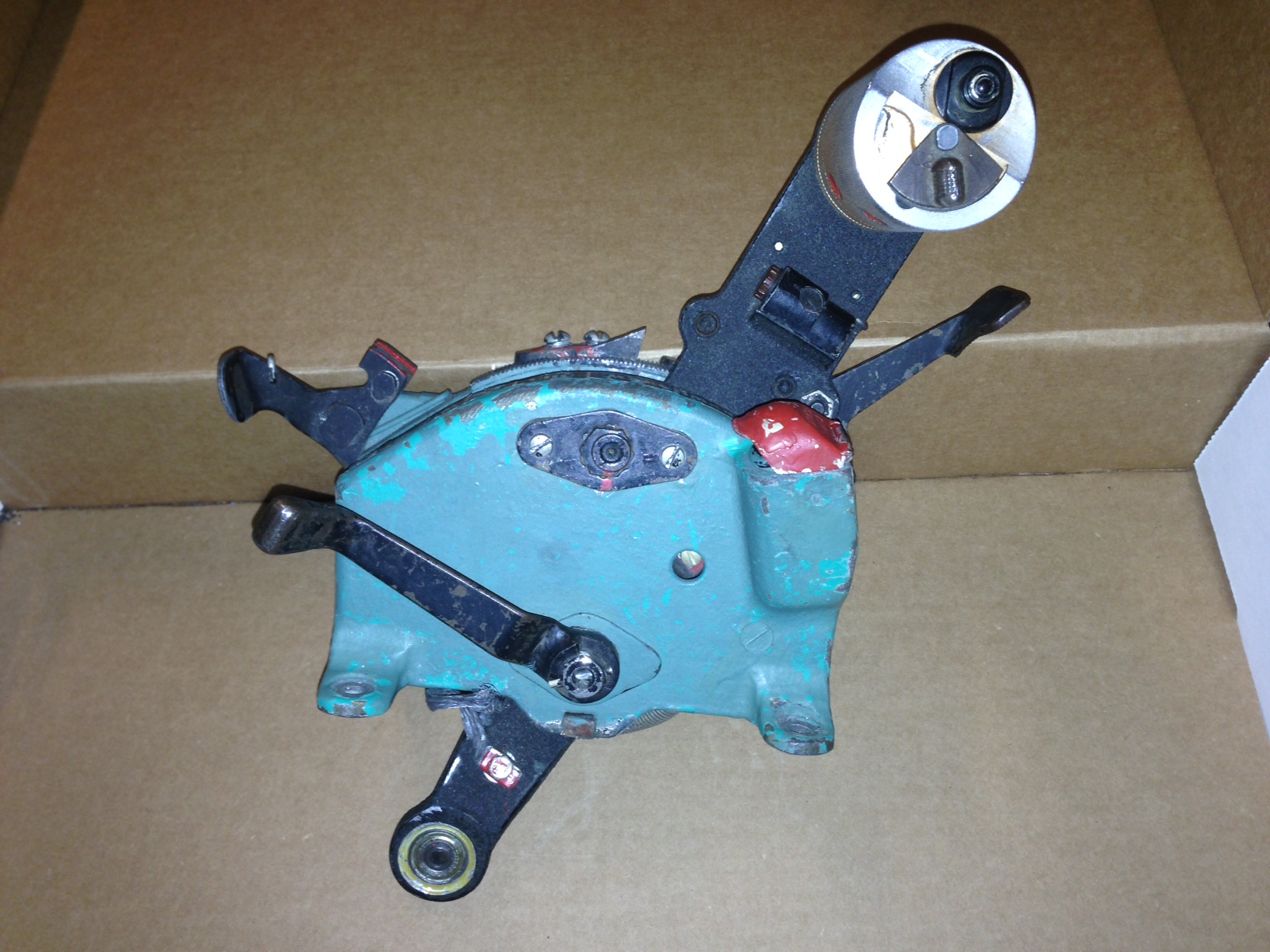
Anybody know what the lever on the back of each throttle half is for in real life? The levers on the front side are for the gate stops, but I haven't seen anything which explains the function of the rear ones?

-
Not a Bis throttle, but basically the same except for the handgrip... Shut off Idle Full MIL 1st stage AB 2nd stage AB
-
Yeah, sorry I haven't really provided any updates in a while. Due to some unforeseen changes in my professional life, I have suddenly taken on a new role with much added responsibilites. Due to the time commitments required, I have pushed back kickstarter release until at least the new year. The project is not dead, it is however delayed... I will still be working in the background to try and finish the units that have been spoken for since the beginning of this project, however I can't give a firm timeline on completion date. Also, with the help of VH-Rock and Pman taking the prototype to Duxford, some knowledgeable individuals were able to take a look at it and recommend a few changes. I will be taking the time to research and hopefully implement these changes.
-
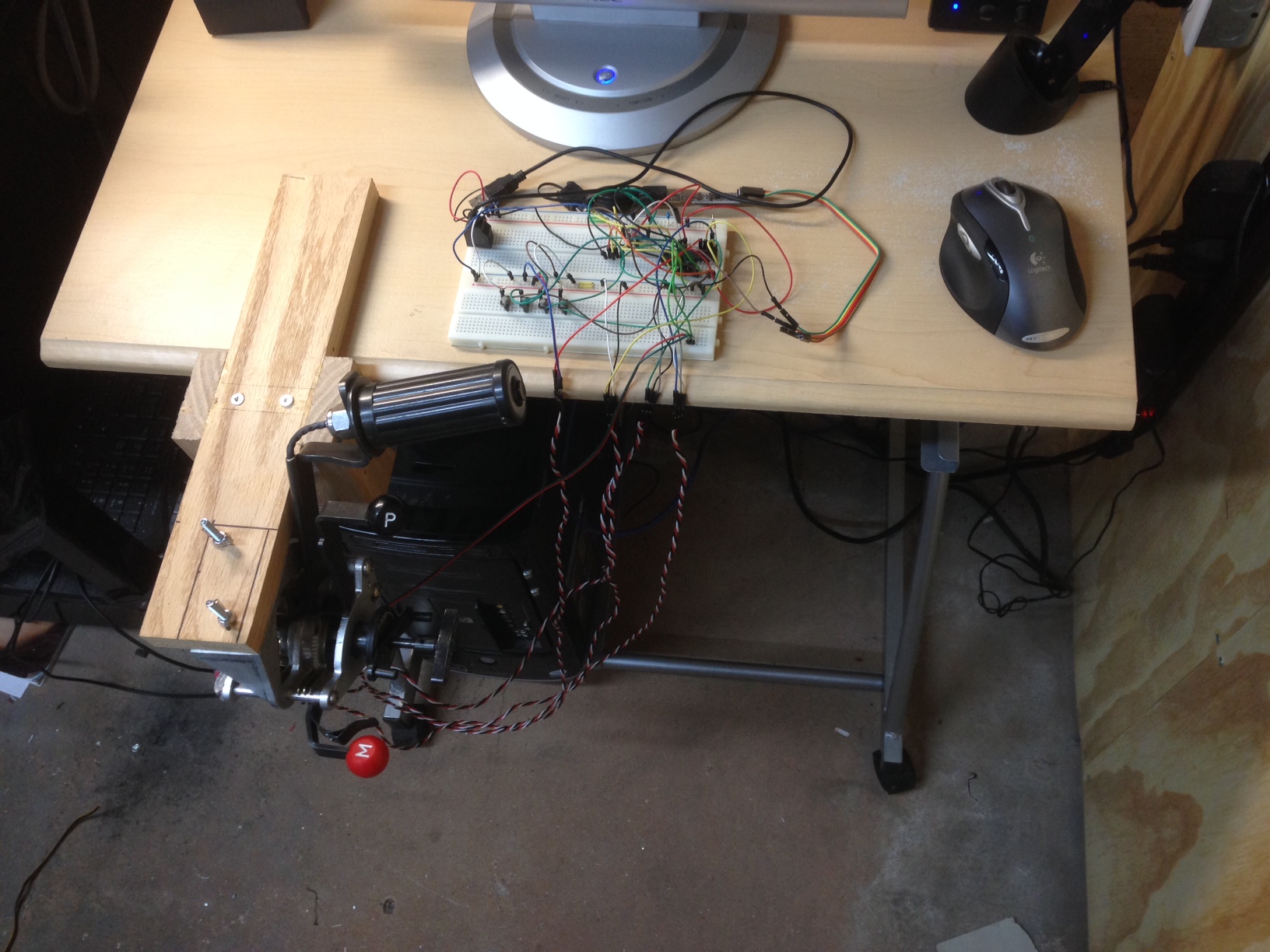
Not quite available yet...however I am pleased to announce that the Kickstarter campaign will begin on October 1st. I'm still working on some of the details and final pricing. If you look at the previous page, you can see a very simple hardwood mount designed to mount the quadrant to a desk. I am still looking into a more polished version of a mount, but I suspect that most people will end up building a simple mount of their own from the dimensions that I will supply for mounting. The mount you see in the previous page was put together for about $10...
-
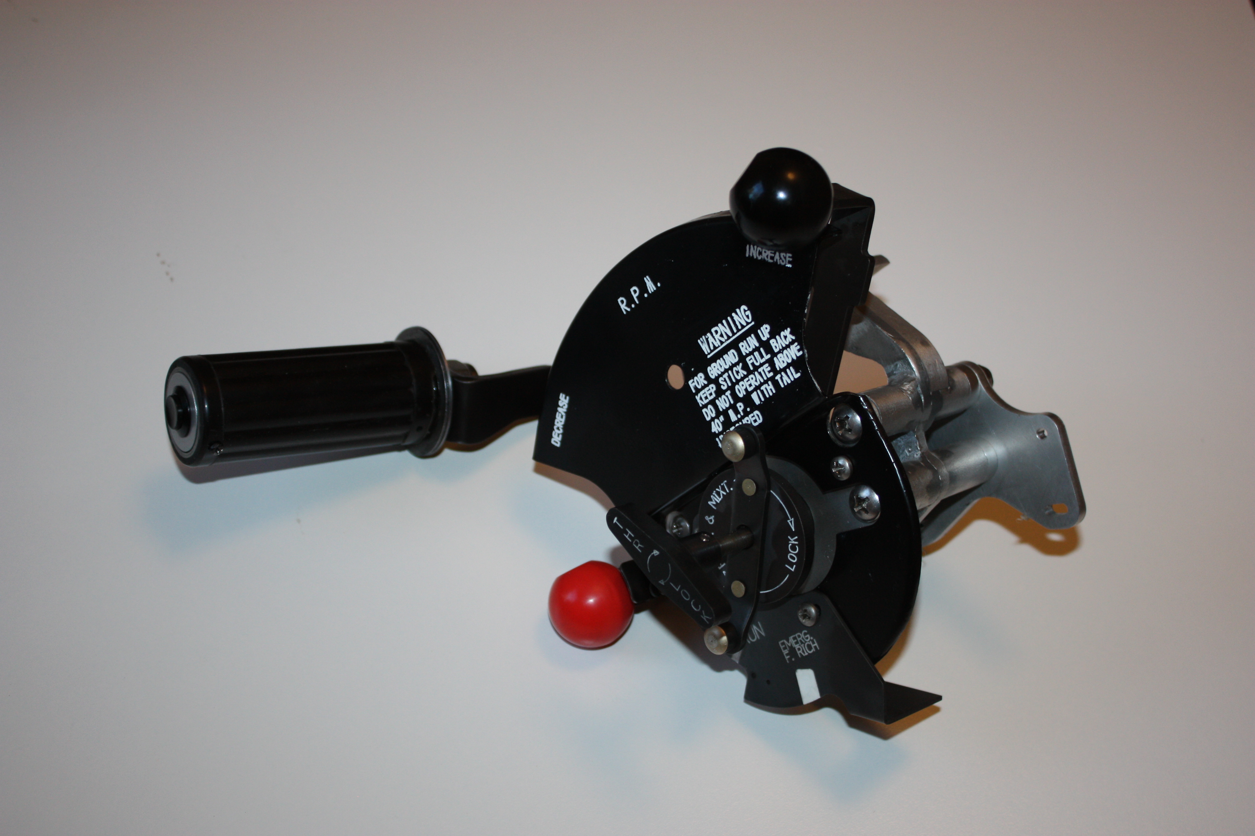
Happy to hear that it will be configured for Flightgear...that's great news! Honestly I'm not that familiar with that sim, how is the mixture lever simulated in it? In DCS, I couldn't find any way to assign an axis to it, so the way the mixture lever is currently programmed is to act as button presses depending on the range it is in. Seems to work pretty good, but I may also need to setup an actual axis configuration if that is how FG and other sims simulate it. There are still some loose ends to tidy up, but I'm getting to the point where the Kickstarter project is almost ready to launch. I'm planning on keeping the initial production batch separate of the Kickstarter project... which will be to build the units for those who have already spoken for them on this forum. Those units will be produced no matter what the result of the Kickstarter campaign is and at a significantly lower price than what they will be offered for afterwards. This is to keep in line with my original thinking of just charging enough to make a few units which will pay for some of the development. Believe it or not the development of this unit is in the thousands of dollars even without assigning any value to the labor I put into it. I'm putting together final pricing now...I'll be back soon with actual numbers and expected delivery info. In other news, a slightly improved prototype (let's call it prototype version 1.1) is on its way to the Duxford Air Show as a first glimpse of the (semi-) finished hardware. Unfortunately due to an issue of overtravel with the gearing for the sensors, (and also from running out of time) this unit is just the hardware (no sensors/USB). The gearing issue is minor (just needs a pinon with a slightly higher tooth count) but I just couldn't get it implemented in time for the show as the sensors had only been temporarily attached for proving out the location/actuation. VH-Rock and Pman of the Virtual Horsemen have graciously offered to bring it to Dux and let a few people get their hands on it. I know I'll get some feedback that will improve the final product. A big thank you to these guys for bringing it to the show! In the pic you can see the unit that is on its way. Slight improvements to the friction knobs (including real solid rivets this time) and face plate. I'm not 100% happy with the engraving on these, but a spring loaded engraving tool will solve those problems shortly. Currently I have to dial these parts up to within .001" flatness on the mill before engraving....and even that doesn't guarantee a perfect end result. The mixture and pitch knobs have been increased in diameter so that they almost match the size of that specified on the drawings. They are within 5% of the stated size, so that's close enough for me (original is 1.125" diameter....these are 30mm).
-
I wish I could. Going with FFB, I'm guessing it will be close to this time next year before I have a decent stick to accompany it. Unless the throttle is a total flop...then I'll have lots of time to focus on the stick! To be totally honest, I only have a couple hours (maybe) on DCS P-51. As soon as I started playing with my bargain basement joystick, I wondered if the tech drawings were available for the P-51 somewhere....and here we are. Don't worry, I need to stay on track so I can get better than a 10 year old computer to play it on (which is what I'm left with right now)! I'm hoping not, but I really haven't sat down and figured out the pricing yet. I know of another company making uncertified replica quadrants which sell for $1875 US....and that is without adding sensors/USB to it. I would actually consider that a fair price after seeing how much work is involved...if I had to pay someone's wages or machine time to make the parts I'd probably be close to that price as well. I'm hoping I come in with a number that is about 1/5 of that...I'll have a better idea shortly. I thought about that...and may offer that as one of the lower model kickstarter rewards when it is launch time. It is somewhat tricky to assemble though...and I would like to know that it is 100% working when it leaves. It has hall effect sensors for all axes and also for the mixture lever (even though mixture lever is simulated as 3 buttons). It is jumping around quite a bit in the video, but don't worry it's not cheap pots causing it. It's a combination of noise on the breadboard, not enough caps to smooth things out and some of my debugging code causing jitter. This will be sorted out...I have confirmed it isn't from the sensors themselves and it didn't exist before I started doing some math on the A to D conversion. I know a few people were wondering what a desk mount would look like. The very simple hardwood mount in the pic works quite well, though it isn't very pretty. A cleaned up version similar to this is what I'm leaning towards. Instructions on how to make your own are an option too...this is a single piece of 1/2"T x 2" wide hardwood and a few bits of standard hardware. If those interested in a throttle had the tools and the willingness to make their own mount it would probably save a bundle on shipping...did I mention that shipping from Canada to anywhere is ridiculously expensive?!
-
It's Alive So....it's been a long time since the last update. First test run in DCS P-51! I apologize for the terrible video...I just wanted to quickly show it's working as intended. It was taken on my old shop computer since I unfortunately had to sell my new sim computer to partially fund this prototype! It just goes to show that DCS P-51 will run on a lowly Intel Q6600 with 4GB ram. I have to say ED did a great job on the modeling of the quadrant...the range of movement in the sim matches the real hardware almost perfectly.
-
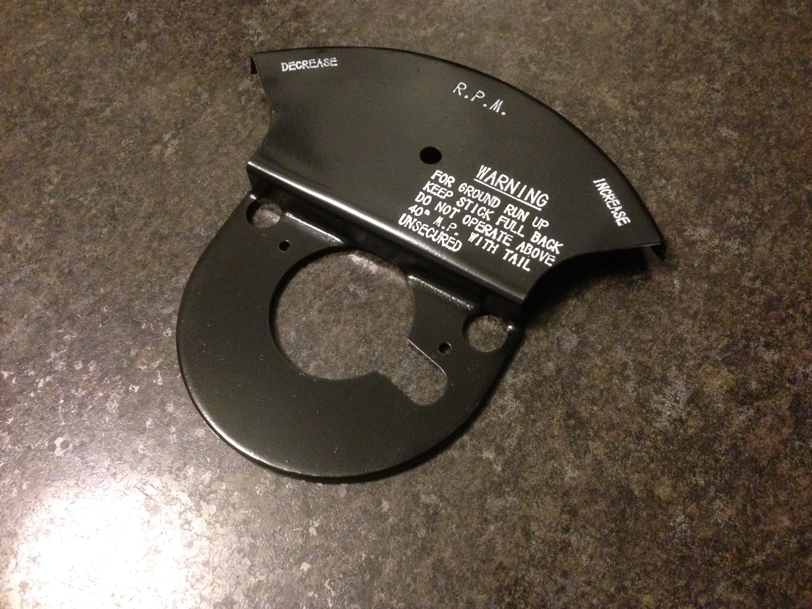
I don't mind if you point out the nits...it only makes for a better end result for everyone (myself included). I would like to know about anything that I didn't get right that I haven't noticed yet. Here are the ones I know about: 1. Pitch lever is not bent correctly. It is currently bent at a 90 deg angle, but should be bent in a radius and angled down toward the front of the faceplate. 2. THR LOCK knob should be a larger diameter (I messed up on the outside diameter when turning this part on the lathe and didn't find out until I had it on the mill). Also, technically this part used to be cast and would have had raised, instead of engraved lettering. 3. The markers on the mixture plate should be rectangular - since I'm machining and then filling with ink, they need to be radiused 4. The handle on the prop and mixt plate is attached with screws instead of rivets and the posts are put together with pop rivets instead of solid rivets. 5. Mixture lever pointer was put together with pop rivets instead of solid 6. Main body is a reasonable facsimile of the original since it isn't currently a casting - wall thickness is lighter in some spots and some webbing between the posts is missing. 7. For some reason the warning message on the faceplate doesn't look like it's quite in the right position...the text size and vertical spacing is good, but something seems off. The bend just below the warning is too deep, so that may be why it doesn't quite look right.
-
Assembly complete! Had (and still have) a couple minor issues, but overall I'm pretty pleased with how it went together. I realized I mixed up the lengths of the bosses on the main bracket, so I was grinding one side and adding spacers to the other. Also the die on my metal bender wouldn't allow me to get quite the right arm lengths on the levers so there is a bit of interference near the end of stroke...but that should be a quick fix. I'm happy to say the lever movement to emerg full rich works great...let's just say you'll never accidentally move it there! It takes a fair amount of force to break the wire. Time to add some sensors...
-
The hall sensors I spec'd are expensive for sure, however they do offer a few advantages over a diy solution. I will be working on a custom solution to reduce cost in parallel, but I suspect I will run into some issues with shielding which will add to the cost and complexity. In other news, the face plate is finished! This one is powder coated and turned out quite nicely. This one is a little worse for wear as I figured out the proper way to form it. I may do a separate black anodized plate, just to see which one I like better, though the powder coating method is pretty slick. I'm open to ideas on how people would like to see this get mounted to a desk...just keep in mind KISS! Mine will be hard mounted to the wall with an L-bracket...but I'm not so sure everyone else wants to do that! Final assembly begins this weekend (minus electronics)!
-
I have a pretty good idea of how it's going to work...hopefully the idea will be somewhat easily accomplished! The plan is to use hall effect sensors, though I don't know if everyone will agree that the extra cost is worth it. The sensors I have spec'd out are about $25 a pop so that's $100 just in sensors to add to the bill. There is the cheaper alternative of building my own sensors using just a hall effect IC and magnet, but then that adds significantly to the work required to build a unit. Like hvengel mentioned, the quadrant is really designed to be mounted by the top flange of the main bracket. I have a couple ideas floating around, but honestly I'm not 100% sure on the mounting yet...I'd like to try a couple different options and see which feels best. I also need to keep the mounting as simple (low cost) as possible, so I can actually keep these units at a price point where people are still able to afford them.
-
Face plate machining completed...ready for forming.
-
I have to say thank you to everyone who is interested in this project for being so patient. It is definitely taking much longer than I anticipated, but I am hoping the result is worth it! Yes, it was definitely a challenging piece...there were many "colorful" words used during the assembly of this piece! I have to say that there will not be many manufactured using this method...for any kind of volume I will need to look at casting, or simplifying the design for machining.
-
Main bracket assy is complete. One more part and then it's assembly and electronics time!
-
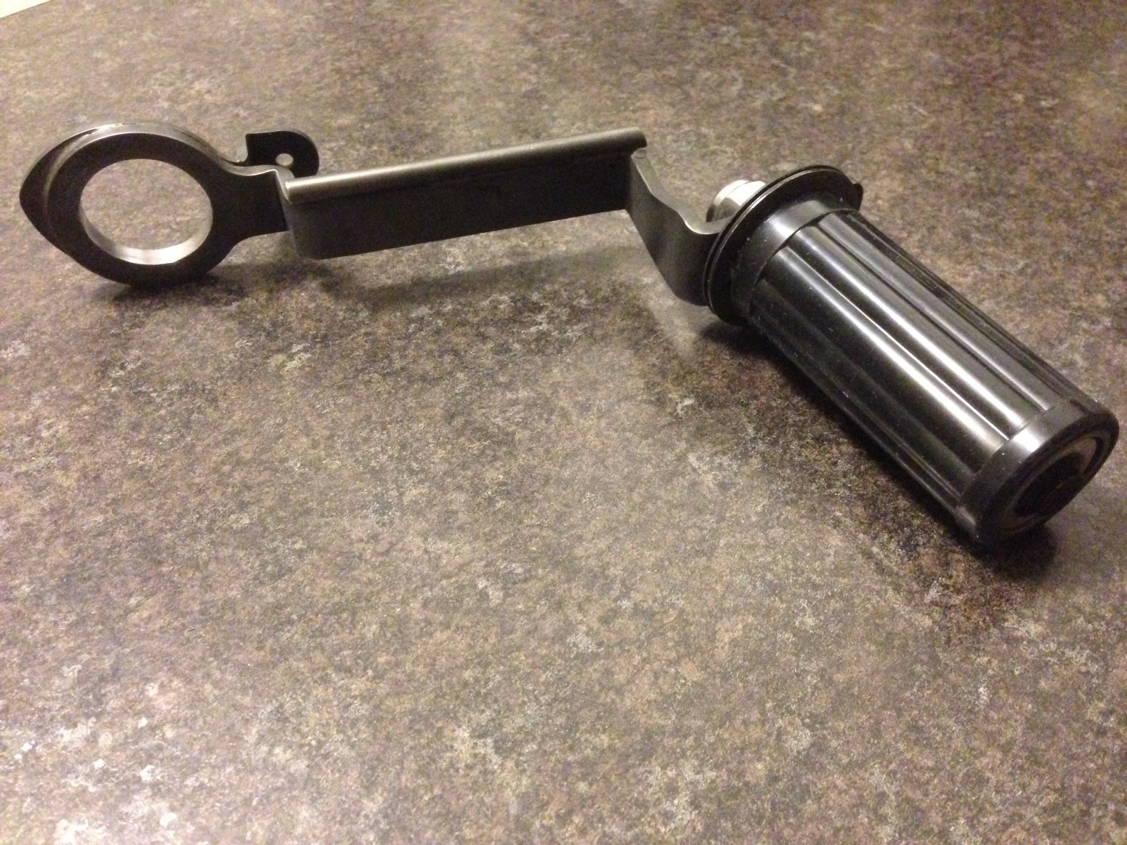
Throttle Lever Complete The throttle lever is complete! - minus electronics. I have to say VH-Rock, you were right... now that it is fully assembled it actually feels pretty good as far as the handle size is concerned.
-
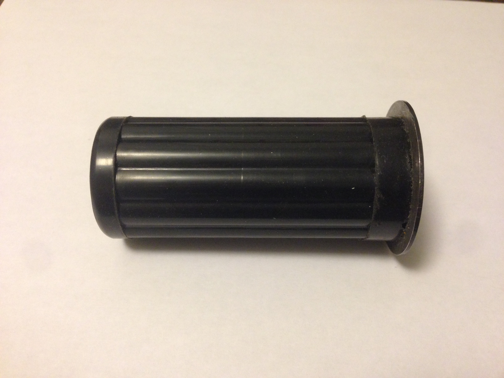
Thanks for the offer...I'll let you know if I run into trouble. Perhaps you could be the first one to port the controller from Pic to AVR! After a long layoff due to shop flooding - drying out - flooding - drying out - repeat... I am finally back at it again. After two failed attempts at building a mold for the rubber grip, the third was pretty successfull. There is one void in it near the flange on the opposite side, but it looks pretty good for a first attempt. The mold was a sacrificial one...I had to destroy it to demold the finished part. The rubber looks and feels just like I had hoped, so it looks like a replica grip will happen on the production units. I'll just have to create a production mold for doing it.
-
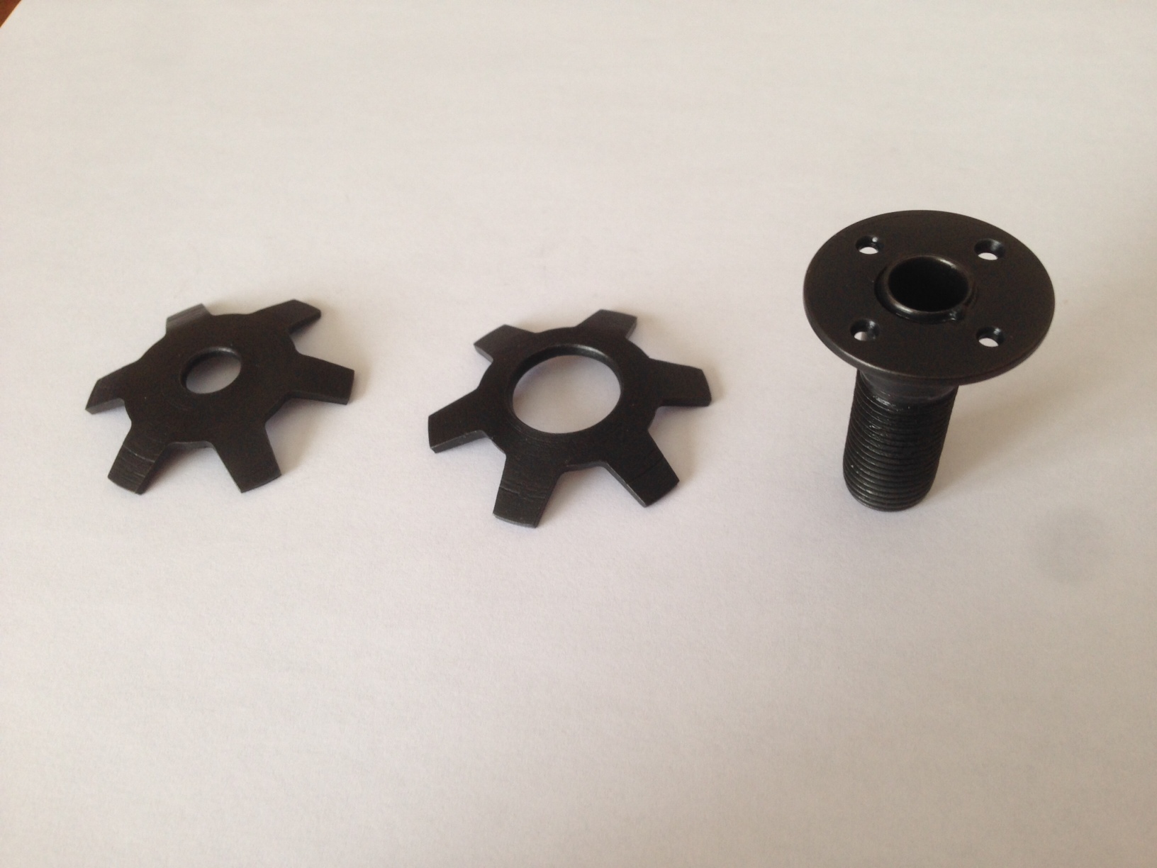
Well, the minor spring flooding turned more serious...the puddles turned into several inches of water in the shop so I am only getting back to work now. Started working on a rough mold for the rubber handle, so hopefully in the next couple days I'll have an actual grip...fingers crossed! The ready made units like Leo Bodnar's would be a significant additional cost, which I am hesitant to go with since I'm a little worried about what the final cost of the quadrant will be after I now realize how much time and material it takes to make one :huh:. I don't want to ignite the PIC vs. AVR war on this thread, but I have done some limited joystick development with PIC, so a custom PIC controller will probably be the route I take...at least initially. I started programming with basic many many years ago...so now I feel most comfortable with PicBasic. In any case, the controller will be open source hardware/firmware so whoever wants to modify/port it will be free to do so. Whichever PIC I choose in the end for the board will have all pins broken out so anything which is unused will be available. I actually have a teensy 2.0 (and one of the other teensies) but haven't really had time to play around with it much. Like I discussed above, the controller will most likely be a PIC since I have some experience with it (haven't got around to learning C on the AVR yet), but it probably wouldn't be hard to port it over to a teensy since the joystick descriptor is really the main part of the firmware. The lever friction is set by the two knobs on the front of the quadrant by squeezing each lever between a set of brass "friction plates". Turning the knobs causes a threaded cylinder to apply more or less spring pressure to the plate/lever stacks to increase or decrease the friction. The springs are similar to a disc washer or belleville....you can see them in a previous post (they look like 6 legged spiders). I believe they should allow the levers to go from almost no resistance to full lock.
-
I may be wrong, but I'm not aware of any rubber which is 3d printable since most rubbers are usually 2 part thermoset resins. There may be a softer plastic which would work sufficiently as a grip though... that may be an option for a limited run. There is always the option of the diamond knurled steel "service order" grip, but I'd prefer the rubber for long flights for sure. UPDATE: actually a quick google search would have shown me that there are "rubber like" 3d printable materials readily available, so ignore my comments above! There is some pretty good progress being made, however there still are a few challenges in the way. I'm trying my best to have a working prototype by the end of the month which I can begin testing. That may be a stretch since sometimes real life can get in the way. I have 3 major components to finish and then to start fitting things together and working on the electronics. I'm currently on hold right now as all of the snow which is now currently melting is causing some issues...minor flooding in the workshop. Not full on flooding just minor "puddles" which should subside over the next few days I hope, then I can get back to work!
-
I think they were even smaller in the early 1900's. One of the houses I lived in was built in the early 1900's. The door frames were only 6 feet high...I'm surprised I don't have a permanent dent in my forehead from living there! Hopefully as you said it will feel more comfortable once it is finished and in the right position. I guess you're probably not supposed to have a death grip on it anyway! For the rubber grip, I am going to try my hand at rubber casting. I have sourced some castable rubber which is the same durometer as that used on the original, but is a different material. It will be made from urethane, so it may not work out so well for someone who is sensitive to that material - apparently some are sensitive to urethane as others are to latex. If the molding fails, I will be trying to source a stock grip which is as similar to the original as possible. How does the P-51 cockpit compare in size to one half of a Cessna 150? It was a tight squeeze for me in a 150...I could barely keep my feet off the rudder pedals and my thighs low enough to clear the yoke so that the pilot could fly. I basically had to sit frozen in one position so I didn't inadvertently start messing with the controls.
-
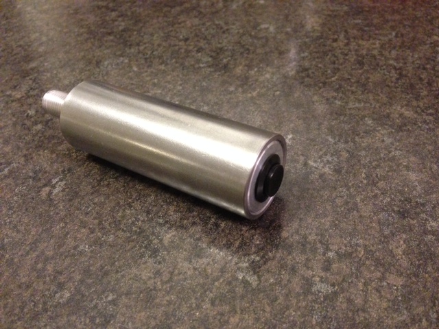
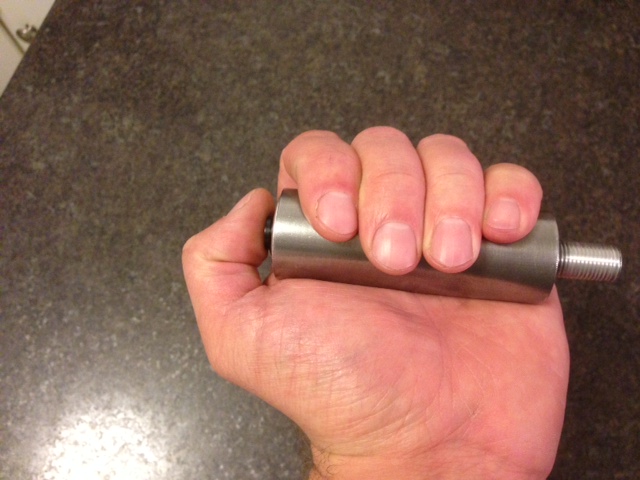
The handle assembly is almost finished...just needs a rubber grip! As you can see by the picture of me holding it, pilots back in the 40's must have had small hands! It's just barely 4 fingers wide...so my hand will be coming off the end once it is attached to the lever. I may have to customize mine for a more comfortable ride! Maybe that is why they told me I couldn't be a fighter pilot all those years ago....since 6'5" is apparently too tall for an F-18 cockpit :( Also finished the arm for the throttle lever.
-
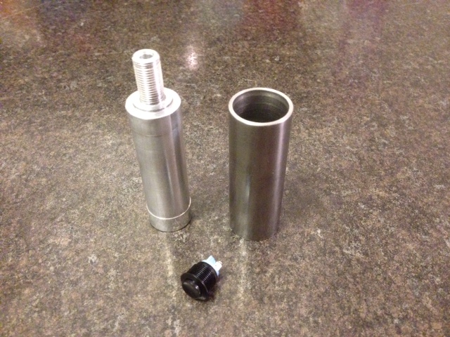
Spring forming complete and brazing complete on the friction knob sleeve...
-
That depends on what you consider reasonable. ;) There will be a very small batch which will definitely be produced...all of which I believe are currently spoken for. I haven't accepted deposits on these units yet, so it's possible some of those may become available. Large® scale production will only be possible through a crowdfunding campaign (kickstarter) which I hope to initiate closer to the summer after finishing the prototype. I hope to use funds raised from a kickstarter campain to expand the machinery range I posess to make larger scale production possible.
-
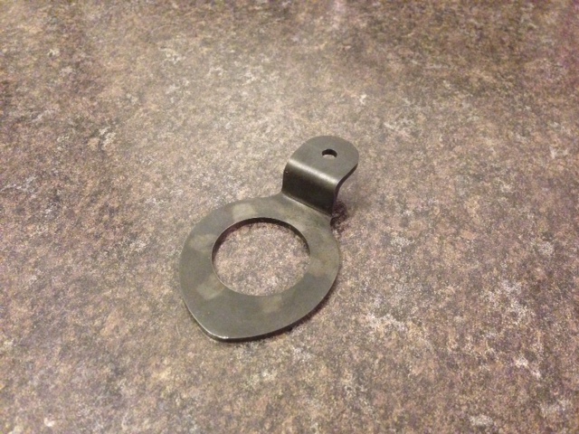
A couple more parts for the bin...