

Kaiser78
-
Posts
32 -
Joined
-
Last visited
Content Type
Profiles
Forums
Events
Posts posted by Kaiser78
-
-
If ED provides that capability then we can certainly update the campaign to take advantage of it.
Maybe you are not aware but we included practice missions with in-air starts close to the engagement area so it's a quick respawn if you die.
We included them so you can practice your tactics, techniques and procedures before committing to the campaign missions.
Without them then we agree it would be alot of flying to get trained up.
You can defeat the AI even on excellent settings once you learn good BFM techniques. It takes time and practice. Check out Sydy's videos for some excellent examples.
Flying against the AI with lower settings didn't present much of a challenge in our opinion so we decided to go against the best the game engine could provide.
Where are the practice missions located? I just purchased the campaign, and I cannot find them in the campaign section. They do not come up in the training section, nor do they come in the My missions folder.
-
I own the hawk and this looks similar. The hawk can cover more ground and get there quicker. Plus the albatross is out and they look to fill the same roll. Love the M2k though. Keep up the good work.
-
No luck.
I tried 250000 and also 125000. Both my export.lua and the one provided. I am going to try using an Uno without it being soldered and see what happens. Maybe there is something with the pro mini that is an issue. I also shared a common ground with all the switches. Just going to hook up one switch and ground and see what happens.
DCS BIOS 0.3.0
UPDATE:
Hooked up one switch on an Uno and it worked flawlessly. It also went from Com 7 to Com 4. Tried another mini pro no luck. When loading the software on the mini pro's compared to the Uno it was a lot longer. Also with the Uno the TX/RX lights were blinking all the time while the MiniPro. Starting to wonder if its the USB adapter that was stopping the correct communication. Either way, thanks IAN. Looks like I'm off to buy some Uno's.

-
Help
To anyone who can help.
Following the hard work put in by others I am converting my pit from strictly Helios to DCS Bios because I am able to make arduino boards at work for projects. I had a pro mini laying around and decided to give this a try. Following the instructions at appears that the switches work when looking at the scrolling cmd file but I get no feedback from DCS.
I have modified the cmd file for the com port my arduino is on (com 7) and I placed the DCS BIOS folder into my DCS Scripts folder as seen in the 2nd picture. I have my own Export.lua file and I have tried using just the original one supplied to me by IAN. Neither seem to work.
Picture 3 is of my device manager showing there are no issues with COM 7. I also just loaded the blinking light example on the arduino IDE just to make sure everything was OK. Which it was. Then loaded my electrical panel sketch based on the instructions given on the web page.
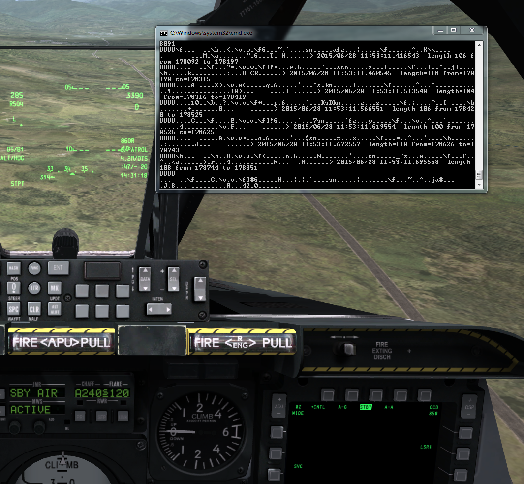
The last image is what I get when I don't have DCS running but go through the 6 switches from the electrical panel. Everytime I toggle a switch I get a result back but nothing that tells me if it is on or off. But it appears that there is a response when I flip the toggle.
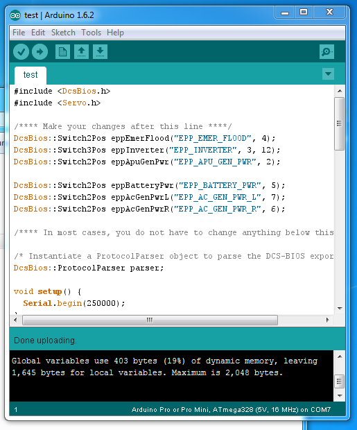
Here is the sketch:
#include <DcsBios.h>#include <Servo.h>/**** Make your changes after this line ****/DcsBios::Switch2Pos eppEmerFlood("EPP_EMER_FLOOD", 4);DcsBios::Switch3Pos eppInverter("EPP_INVERTER", 3, 12);DcsBios::Switch2Pos eppApuGenPwr("EPP_APU_GEN_PWR", 2);DcsBios::Switch2Pos eppBatteryPwr("EPP_BATTERY_PWR", 5);DcsBios::Switch2Pos eppAcGenPwrL("EPP_AC_GEN_PWR_L", 7);DcsBios::Switch2Pos eppAcGenPwrR("EPP_AC_GEN_PWR_R", 6);/**** In most cases, you do not have to change anything below this line ****//* Instantiate a ProtocolParser object to parse the DCS-BIOS export stream */DcsBios::ProtocolParser parser;void setup() {Serial.begin(500000);}/*Your main loop needs to pass data from the DCS-BIOS exportstream to the parser object you instantiated above.It also needs to call DcsBios::PollingInput::pollInputs()to detect changes in the state of connected controls andpass them on to DCS.*/void loop() {// feed incoming data to the parserwhile (Serial.available()) {parser.processChar(Serial.read());}// poll inputsDcsBios::PollingInput::pollInputs();}/*You need to definevoid sendDcsBiosMessage(const char* msg, const char* arg)so that the string msg, followed by a space, the string argand a newline gets sent to the DCS-BIOS import stream.In this example we send it to the serial port, so you need torun socat to read the data from the serial port and send itover UDP to DCS-BIOS.If you are using an Ethernet Shield, you would probably wantto send a UDP packet from this subroutine.*/void sendDcsBiosMessage(const char* msg, const char* arg) {Serial.write(msg);Serial.write(' ');Serial.write(arg);Serial.write('\n');}/*This subroutine gets called every time a message is receivedfrom the export stream (you need to define it even if itdoes nothing).Use this to handle outputs which are not covered by theDcsBios Arduino library (e.g. displays).*/void onDcsBiosWrite(unsigned int address, unsigned int value) {}}PS ignore the smiley faces. That resulted from the : P in the code when I copied it.
-
Looks good. I can't wait for my house to be finished so I can finally make the side panels. As for the arduino, I spend most my time reading and learning here.
-
Those of you looking to use arduino a in your pits, http://www.sparkfun.com is having a sale this weekend.
-
Yeah we do all of those things. Maybe it's my wingman goofing up somewhere. It wouldn't be the first time. It was working for the longest time. Maybe he did something different.
-
No I am not lasing. I find the target in my tgp and tms up short to lock. Then tms up long to make it my spi. Hook my wingman in my tad and send. If I need to lase when would that need to be done? Before I tms up short to lock?
-
Looks like my dream will be short lived. They said that at 6 foot 3 I was too tall when I talked with them today.
-
Yeah it's always off. Doesn't matter if he sends me or I send him.
-
When sending my buddy my spi over the net he accepts the tasking and it's never correct when he looks in his mfcd. I know this was a problem long ago but is anybody still having issues with this?
-
Thanks Thick8.
-
Excellent job!
-
Yes! Thank you, thank you, thank you.
-
Does anybody know if this is for real or not?
http://www.youtube.com/watch?v=sET5uQ4PfQI
If it is, I am seriously considering making a trip to Russia to take part in this. Not to forget your women are beautiful.
-
Progress update 3/12/14
I was able to get the laser working properly and I was able to print off a new AHCP. I did it with two different thicknesses of plastic. The first was .220 and that ended up being way too thick. Then I went to .60 and found that it was stronger than I thought. I plan on putting leds on the baseplate. Since it is all in clear acrylic I have already printed out at a local print shop the lettering on translucent foil and will just stick it to the top layer of the acrylic.
Here is the panel procedure I am going to use.....http://www.hanskrohn.com/BuildingTips/Backlit_Panels/Backlit.htm
-
I just had the same thing. It was blinking blue. Since it was so new amazon replaced it for free.
-
Web server swapped and will hopfully stay alive for more then some hours.
Started on the CMSC. Missing lightpanel (or rather the printout) still. Display in place but not yet interfaced
http://www.strandedduckling.com/CMSC_temp.jpg
Cheers
Gus
Yes! I've sent so many people there only to have it down.
-
Having just started myself I didn't even know of this site. I first found viperpits to see what people were doing. From there my buddy started talking about dcs a10 and I decided to make an a10 pit. Google found me stranded ducklings web page. Then I found out what was possible with my own skills compared to his. Figuring out what I couldn't do was easier than what I could. Enter gadrock Helios. That is my interface software. Then since I traveled for work I started looking at all kinds of planes at the Pima air museum in Tucson. Took lots of pictures of various cockpits and then started sizing up the pit with my size at 6 foot 3. I will see if I can upload some of the pictures that may help you. Be sure to check out lindens pis and deadman. Those are really impressive.
-
After the last update I had all kinds of problems in Helios and dcs with button mapping. I removed the module in dcs world and then reinstalled it. Make sure to copy your key just in case. Then I went into Helios and reloaded my profile and no issues.
-
I thought I would post up probably the most important things. AKA the failures I had.
1. The height of the center console.
Being so tall I made my pit very short. IE my knees would cover the engine cluster and sitting for 3 hours on a mission would kill my back by the time I was done. I ended up having to add 6" of height to allow for the comfort level. Looking at pictures I was able to determine that the knees should be even with the lower line of the engine cluster. So I had to modify my pit to be the same.
2. Chair
Based on my small room (until the house is built) I could only build a center console and choosing a chair is paramount. Most people here are using an aces 2 seats and that may be in the future for me but now I have to use a desk chair. Incline for comfort is very important and sitting upright at a desk does not allow for a comfortable flight. I had to drill holes and put a bolt through the bottom to make the proper angle for flying.
3. Xkeys
This was probably the biggest waste of my time. I spent hours soldering breakout boards for all the inputs only to have an update go through with DCS and have to rekey all of those inputs. (Seems every update I have to rebind all my HOTAS keys anyway). All that time and breakout boards were a total waste of money. It was much cheaper and easier to buy Leo Bodnar BBI interface cards.
4. TFT monitors
I bought two small TFT monitors with a VGA/DVI for the MFCD's and although they worked all the circuit boards made the back of my pit very messy. It also limited the location of my PC unless I bought longer cables. With my video card I only had two outputs so either I would have to buy another video card or I would have to go with the lilliput monitors via USB.
5. USB Hubs
Make sure they are powered USB hubs! With the lilliput monitors on their own HUB and everything else on another hub. On my motherboard I kept getting a B2 error and all kinds of windows restart problems. Mind you I only have DCS on the machine. (Its not even used to connect to the internet except through DCS.) I also found it better to have 3.0 USB ports instead of 2.0.
6. Track IR
If you can find a track IR 3 and buy the vector addition is works just as well as the Track IR 5 in my opinion.
7. Remote switching
Wireless remote....http://www.amazon.com/gp/product/B000G80V28/ref=oh_details_o01_s00_i00?ie=UTF8&psc=1
My layout is like this...
Computer > Wireless remote 1 > USB HUB 1 > Lilliput monitor 1 and 2
Computer > Wireless remote 2 > USB HUB 2 > Rudder, throttle, fighterstick,
Computer > Wireless remote 3 > USB HUB 3 > Thrustmaster MFCD X2, Leo Bodnar boards X3
This allows me to only turn on what I need and gives me additional control over the individual components to help for troubleshooting issues. I just hide the remote. No burn out on my lilliput monitors also.
Hope this help eliminate some of the mistakes. I am sure there are more and I will list them as I can.
-
Save up for the lillyput monitors. They are excellent. Be sure to check ebay and amazon quite often. Sometimes you can pick them up for $100 new.
-
I would like to introduce myself seeing how nobody probably knows me here. I have only asked a few questions concerning scripting for mission editing but about 6 months ago my buddy asked me to pick up A10. Up until now I had been playing Janes ATF and USNF regularly. I did the MFSX thing for a while.
Because of my background I am always building things...much to the wifes dismay. I used to build custom airsoft replicas, Home automation devices and now a pit. Finally, a PIT! I wish I would have found this section sooner. It would have made my life easier but sometimes doing it the hard way is the way to go. There are lots of people with good information on here and I will be modifying my pit to some of your simpler ways. Some of which I already have. All my stuff is custom made to my own dimensions as far as I know and by attending numerous air museums throughout the States.
My height on the pit from the ground is much higher due to the fact that I am pretty tall. I added supports making it look like the layout from Dimebug.
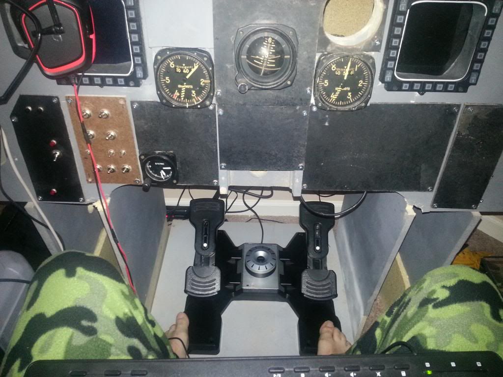
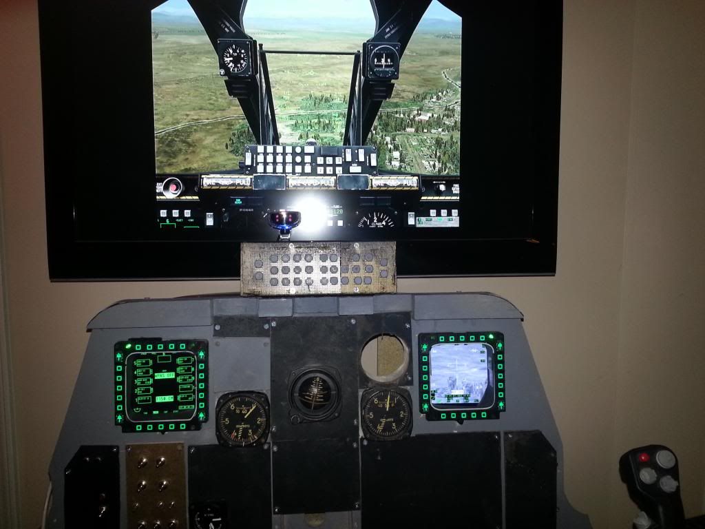
Im just outside Chicago in NW Indiana so during the winter months (when hunting season is over) we have a lot of time and crappy weather. Following are some pictures of my progress. I hope you guys like it.
The last thing I did was order a laser printer and started to test it out. I should be getting some good panels soon.
I am using a program called Helios by a guy named Gadrock with Leo Bodnar boards for my interfacing. If he is on here, great work man. I appreciate the hard work. There was another guy on StrandedDuckling from Sweden I think that had some good info. Needless to say I have some reading to do and since I am moving to a new engineering department and I get to use the industrial 3d printer we just bought I am sure I am going to be testing that thing out with my own designs.
Long and the short, thank you all for the help your about to receive and if there is anything I can help with in the community please let me know. Also if anyone is in the midwest and wants to meet up at the midwest gaming classic in Milwaukee let me know. I'll be sure to stop by and say hello. Clearly I have a long way to go as some of these other pits are just awesome.
-
Duckling is your site down?


How good is this campaign considering the UFO AI FM/DM?
in F-5E Aggressors BFM Campaign
Posted
Great. That worked. Thank you.