
quick
-
Posts
28 -
Joined
-
Last visited
Content Type
Profiles
Forums
Events
Posts posted by quick
-
-
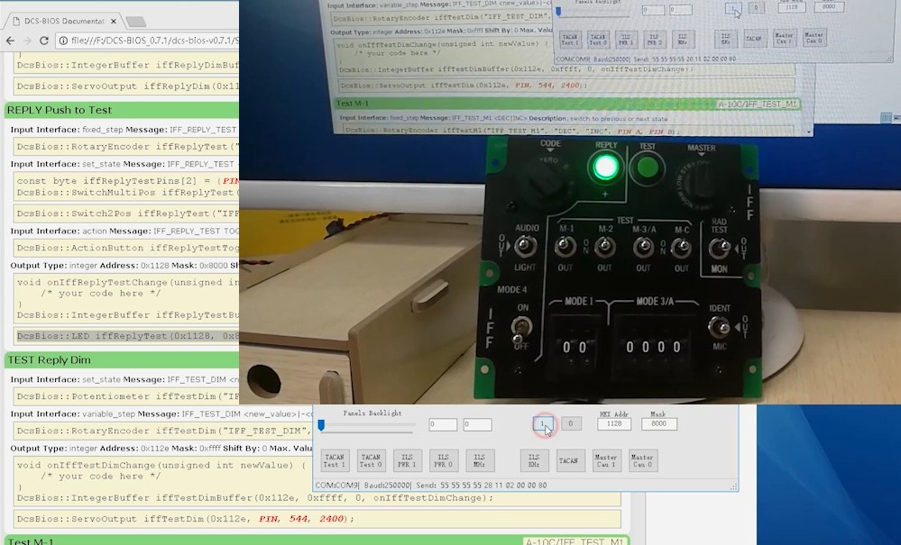
IFF panel Indicator Light
By the way , the IFF panel REPLY Indicator Light and TEST Indicator Light :
1) Edit the file DCS-BIOS\lib\A10C.lua
2) add two lines
definePushButton("IFF_TEST_TEST", 43, 3018, 796, "IFF", "TEST Push to Test")
definePotentiometer("IFF_TEST_DIM", 43, 3021, 901, {0.0, 1.0}, "IFF", "TEST Reply Dim")
--******************************quick edit*********************************
defineIndicatorLight("IFF_REPLY_LED", 798, "IFF", "REPLY LED")
defineIndicatorLight("IFF_TEST_LED", 799, "IFF", "TEST LED")
--**********************************************************************************
defineTumb("OXY_EMERGENCY", 40, 3003, 601, 1, {-1, 1}, nil, false, "Oxygen Regulator Panel", "Oxygen Flow: Emergency / Normal / Test")
defineToggleSwitch("OXY_DILUTER", 40, 3002, 602, "Oxygen Regulator Panel", "Oxygen Normal/100%"
3) Arduino code:
DcsBios::LED iffReplyLed(0x112a, 0x0080, PIN);
DcsBios::LED iffTestLed(0x112a, 0x0100, PIN);
4) Enjoy;
Test video: https://www.bilibili.com/video/av29097580
The issue same as this thread
-
The video has been uploaded.
-
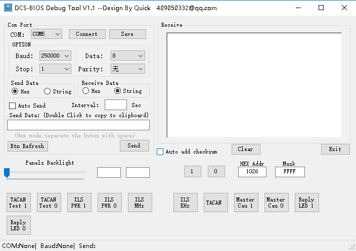
This is a small tool I wrote, in order to debug DCS-BIOS panels for my pit. Now share it with everyone, hope every fan has his own pit.
DCS-BIOS Debug Tool, debug DCS-BIOS panels without start game.
It is based on serial communication, can send the brightness of the panel backlight, integer address bits (such as indicators), you can customize the command button.
System: Windows 7/8/10 , need .NET Framework 3.5
The video will upload later. Sorry for my poor English, can only make English subtitles.
Enjoy!
video:
https://www.bilibili.com/video/av28620446

-
IFF Panel
1) I try to edit the file DCS-BIOS\lib\A10C.lua
find:
define3PosTumb("IFF_OUT_AUDIO_LIGHT", 43, 3009, 301, "IFF", "IFF Out: LIGHT - OFF - AUDIO")

replace:
defineTumb("IFF_OUT_AUDIO_LIGHT", 43, 3009, 301, 1,{-1, 1}, nil, true,"IFF", "IFF Out: LIGHT - OFF - AUDIO")
Enter the game test, it looks normal.
I have not tested other, you can try to modify it.
-
CDU continue
It's almost done.
The next step will be programming.
The phone is not a good camera.
-
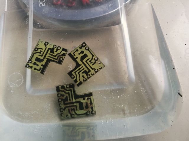
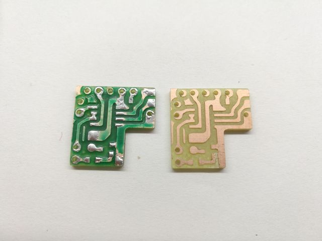
CDU PCB production
The last method of making a PCB failed, so I used the original method, but with a few more steps.
1. CNC drill and cut
2. print film paper
3 with 365nm UV light irradiation
4. Development
5. Etched
For the first time using this method of making PCB, pay a lot of tuition, wasting a lot of material, or not perfect, and then slowly strengthen.
figure 1: ready to irradiation
figure 2: PCB OK
figure 3: Cut the acrylic panels, and test the buttons setup position
-
can you give a link for this display ?
The purchase link is in Chinese language. I can send you a message.
Not wishing to be a smart arse because simms mean so much to each builder.But with the A-10C replicating the CDU screen on the MFD and the pinky/modifiers able to replicate every key press from your keypad, why the buzz to n#make a CDU?
Im not beind a smart arse, obviously every panel can be cheated, but why would the A10C put the CDI screen upfront if it didnt anticipate it to replace the CDU...
Just a genuine thought.
I'm sorry, Google Translate can not accurately translate the meaning you want to say, I did not understand.
I have a CDU on my road map and I see it just as a technical challenge. And nothing can beat flipping real switches and clicking real buttons. :)Though yes, pinkie and keyboard is the easy way for this, but some like it hard. ;)
Great:thumbup: "nothing can beat flipping real switches and clicking real buttons."
-
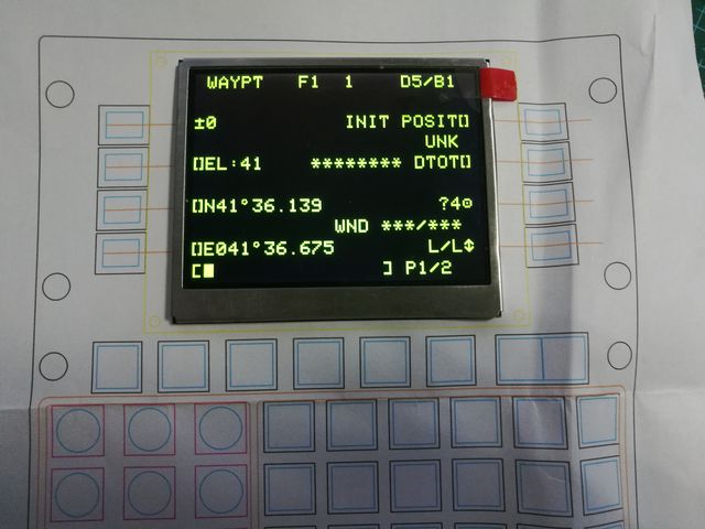
CDU design
I chose a 3.5 inch TFT screen. It is very cheap, about 12 $.
Serial port screen, comes with driver chip, faster refresh rate, more simple development.
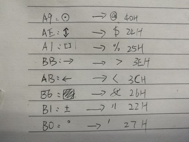
There are some special characters in DCS-BIOS conversion, I try to convert to basic ASCII characters.
First of all these characters used (A10C is a picture format) extracted, made font, save to the screen flash ,and then output characters through the DCS-BIOS and displayed on the screen.
Some trouble is that this will need two serial ports, no choice, only mega2560.it's a bit big.
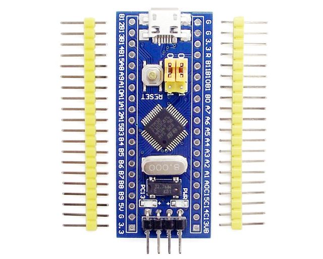
I found Arduino to support STM32 MCU, but compile error in DCS-BIOS.
This MCU is very powerful, high-speed, multi-serial, and cheaper.
https://github.com/rogerclarkmelbourne/Arduino_STM32
Now many devices are made of modules, easy to develop, but need more serial, SPI, I2C and other communication resources.
-
Hm... If you print the knobs, why not make a negative shape for the arrow and fill it with ink?
I guess it'll be easier filling than painting with a toothpick or a small brush.
Anyway: Keep up with your work! I like following the progress.
It's have a negative shape for the arrow.because I did not care enough when filling the paint.
-
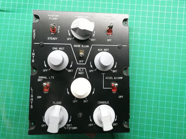
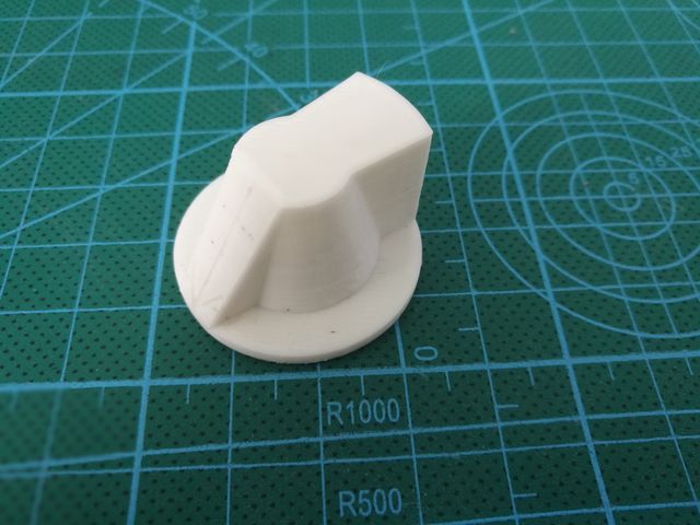
Lights Panel
I tried a lot of ways to make knobs and spray paint.
3D printer production knobs, and some direct spray paint, and some with sandpaper and then spray paint,some soaked with smooth liquid.
There is the pattern of the arrow above, I use a toothpick difficult to draw a good, should buy a strokes pen to try.
Feeling paint is not easy.
-
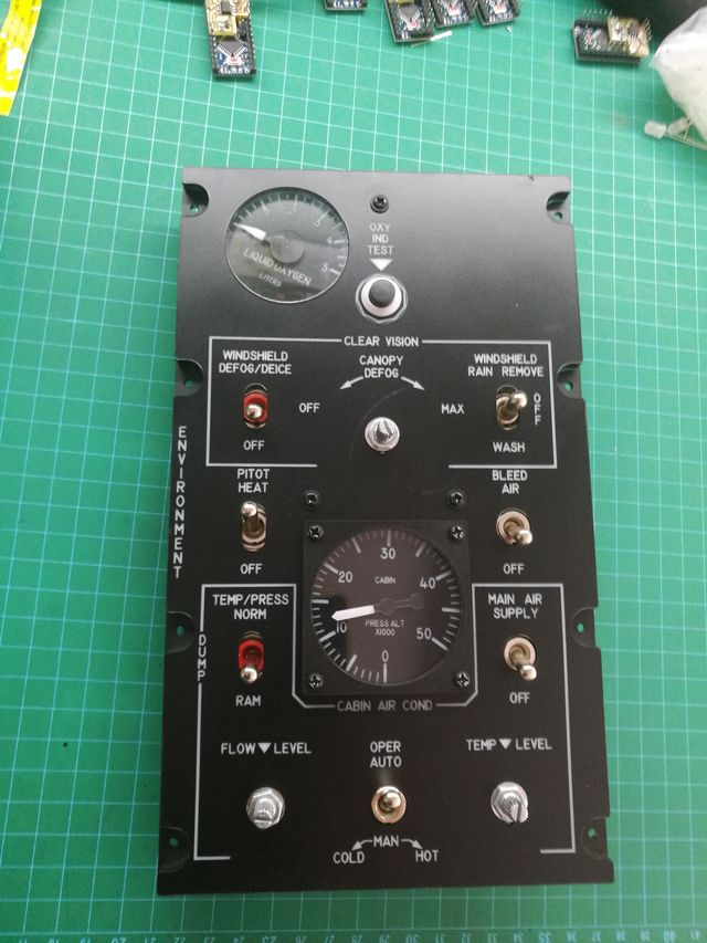
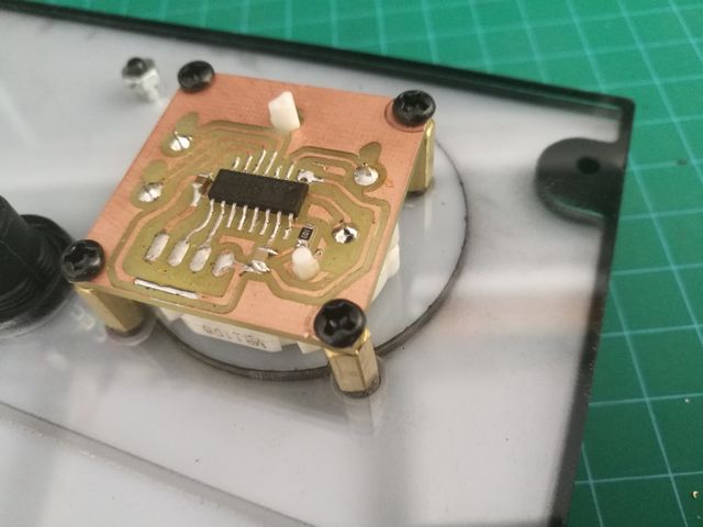
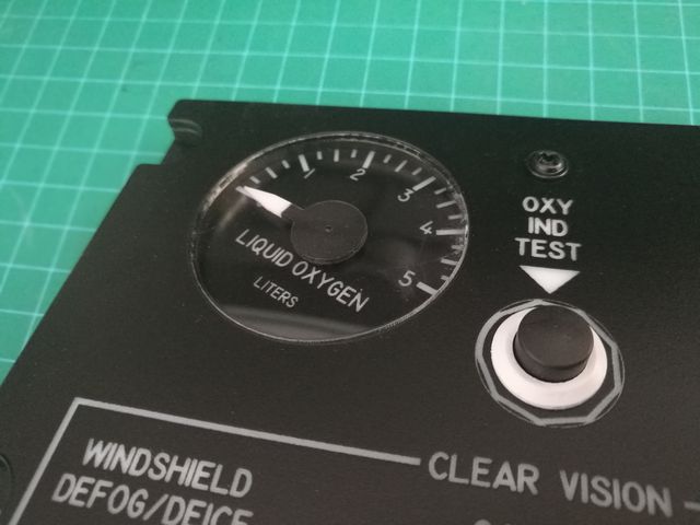
ENV Panel
I used a auto meter stepping motor like the Switec X27 and VID29.
Driver chip using VID6608, dual-channel instrumentation stepping motor chip.
-
Be careful with ferric solutions, one of them is a serious water pollutant which I'd bad for Eco systems. Not sure which one but please dispose of properly!
Waste liquid containing copper ions, is not conducive to environmental protection.
Individual production is relatively small, you can collect the waste, Precipitation crystallization.
In my hometown, many chemicals such as ferric chloride(FeO3) have been banned from being sold to individuals.
There is an environmentally friendly etchant on the market for sale and can also be used,I don't know its chemical composition.
-
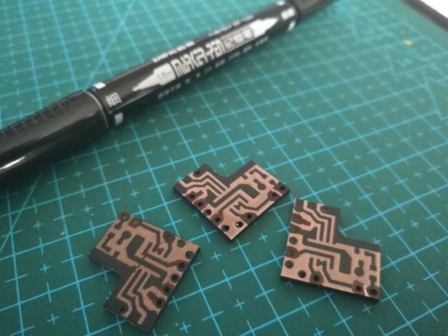
New way to make PCB
After the experiment this is not a good idea.
Laser engraving will form a layer of oily film, with its protection, it is difficult to etch.
I try a new way to make a PCB.
1.Use CNC to drll holes and cut.( if not have,you can drill holes after the 5 step)
2.Use Spray Paint to paint PCB.
3.Use a laser engraving machine to remove unwanted protection.
4.Use oil Marker-pen to correct the graphics.(Not necessary)
5.Use an etchant to make a PCB.
On the etching solution, it can be hydrochloric acid (HCL)+ hydrogen peroxide(H2O2), anhydrous ferric chloride(FeCl3), and others.
The HCL+H2O2 mode have a fast speed,but in some places it is difficult to buy.
Compared with CNC manufacturing PCB, it has high speed.
-
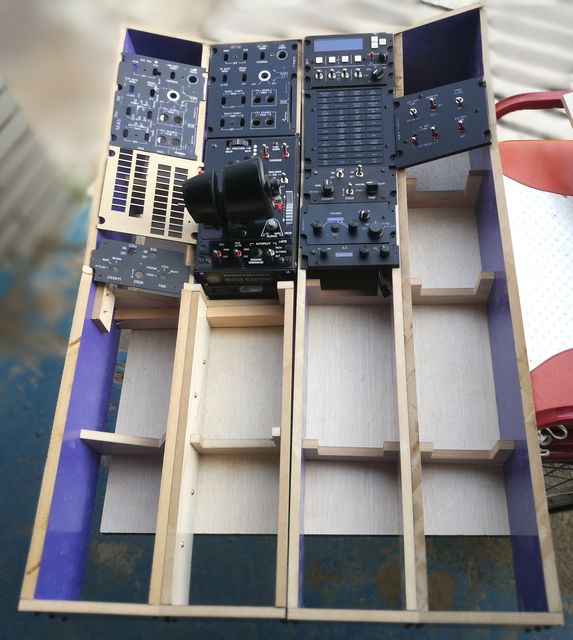
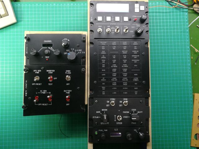
The frame of the console
It's time to find a home for these panels.
The material is useless floor, 12mm thick.
The CNC maximum range is 300x400, only some small parts of the processing, the other with a curve saw to complete.
-
Are you using the CNC to engrave the PCB?
I really should try and sort mine out, I just have zero enthusiasm for anything lately.
Yes, I used the CNC engraving machine to do the PCB, but I found it very slow.
I am looking for a new method, doing the test, and later I will show it in my thread.
-
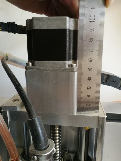
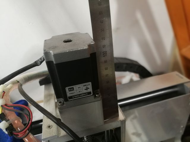
The CNC problem
A cheap 3-axis engraving machine, I found a problem, CNC engraving depth often changes. I found the reason that the Z-axis stepper motor was too small to hold the 1.5KW spindle motor. As the driver chip supports the maximum 3A current, so the replacement of a stepper motor, and now use up much better.
-
It's OK
In my Thread https://forums.eagle.ru/showthread.php?t=194670
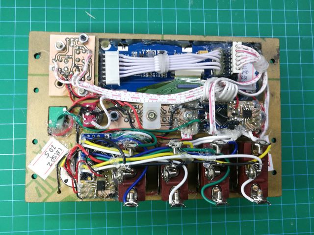
I use arduino pro mini ,every board use a max487 .
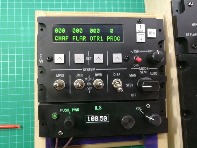
The ILS panel use I2C OLED screen. It's OK.
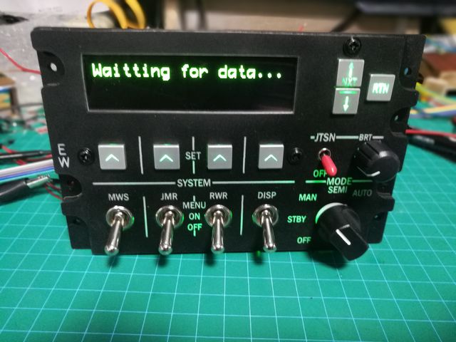
The CMSP panel use SPI interface OLED Screen, It's OK. but,the Pro mini not have enough pins to control so many buttons ,so I use two boards.
-
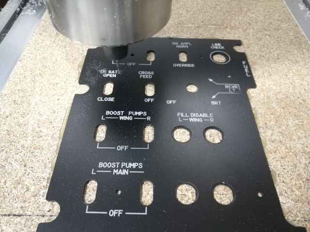
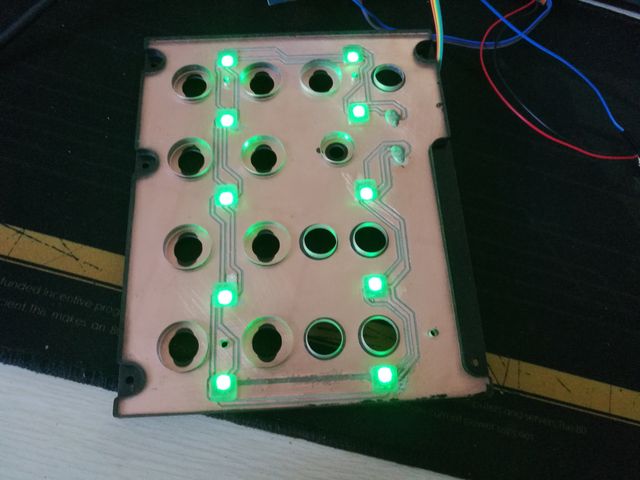
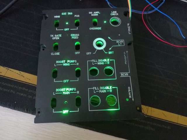
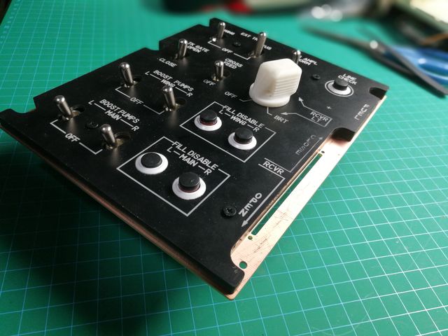
FUEL Panel
It is a new attempt, but the result is not good.
I tried to put the LED on the PCB, but the light was not uniform.
And the CNC machine have some problems.
Mission Failed!
Continue the next attempt.
-
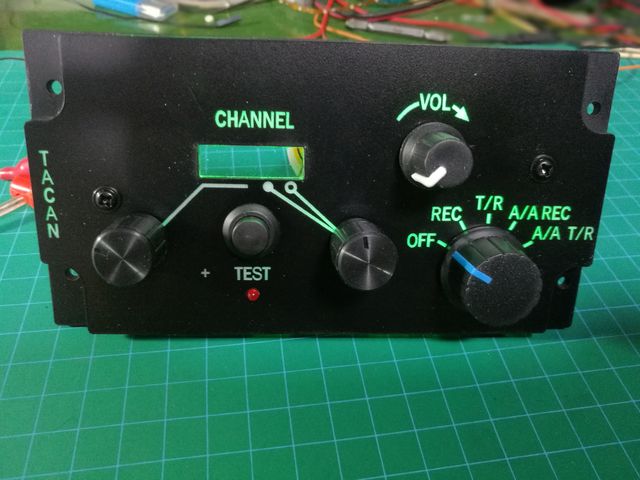
POWER & TACAN Panel
The switch and knobs have changed , easy to buy in market.
Screen use 0.91 inch OLED, same of the ILS panel.
-
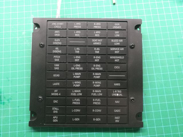
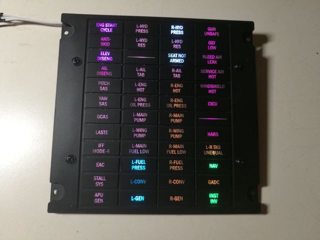
Warning panel
It's use the RGB LED with WS2812 chip, only need 4 wires every lamp, 5V, IN, OUT, GND. You can change color and bright through MCU.
What color do you like,you can change it.
There are some bugs on the panel,it does not matter.
-
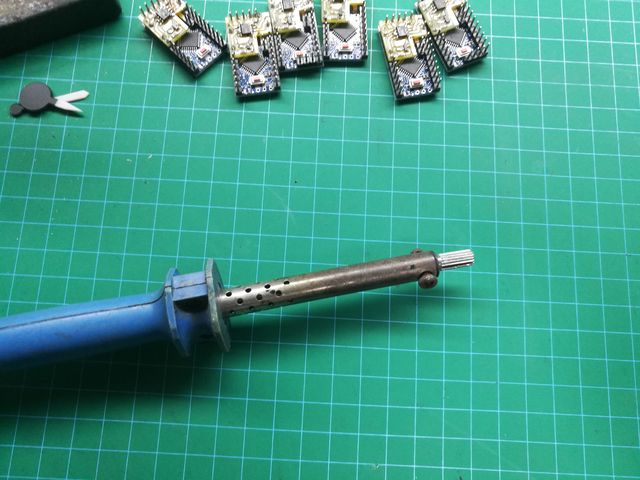
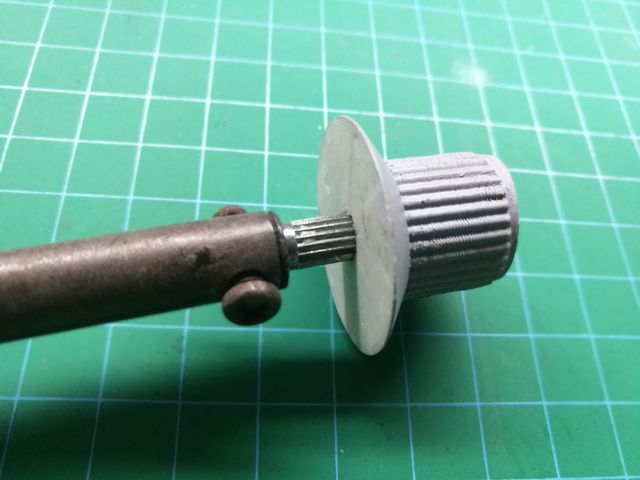
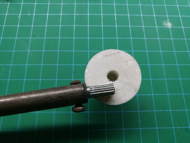
Tools
A simple tool to make hole in a knob.
The PLA material is very brittle, drilling will lead to cracking. So use a soldering iron.
You can use the axis of the potentiometer
-
 1
1
-
-
Warhog ! The perfect cockpit you do is an example of my learning.
-
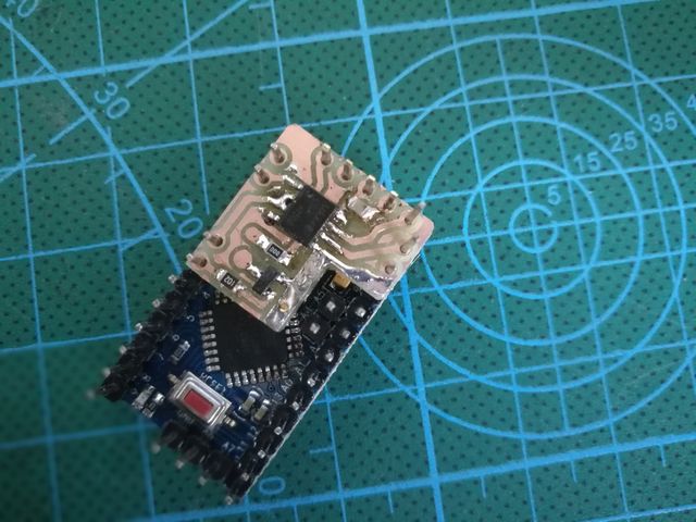
MCU and Knob
MCU is pro mini , DIY the PCB and put the MAX487 chip to link the net,and another pin use PWM control the backlight.
Try to use the 3D print ,the PLA material.
-
CMSP
Use a 3.12 inch green OLED screen .
-
1
-


My A-10C preparation
in Home Cockpits
Posted
FILL DISABLE button looks good.
If you use black screws, it will look better.
Continue your great work.