
Dadzilla74
-
Posts
52 -
Joined
-
Last visited
Content Type
Profiles
Forums
Events
Everything posted by Dadzilla74
-
https://www.youtube.com/watch?v=FYr4yIk01-o This uses 2 Arduino mega boards and multiple displays. If you would like any information let me know.
-
Hi Guys, FYI. I have done some tests with LOTATC and the IFF modes 1&3 work. Mode 1 allows a two digit code for the aircraft type and the Mode 3 allows a 4 digit squawk code. These can be sent to LOTATC using the I/P button on the UFC or the Indent button on the SRS radio toggle. This will allow atc to find you quickly and know the airframe you are (if your server has assigned mode 1 codes for the different airframes) If in a group flight ATC will assign numeric squawk codes for each flight to show up as a group. Mode 2 is another 4 Digit code that can be inputted yet still working out the why, how and when to use mode 2.
-
Guys, I would just like to say thankyou for the discussion and its great to see the passion we have to make the F-18 as realistic as possible. Lets hope ED notices this and tries to spend some time on the IFF systems and explanations.
-
Its a pity that this is not explained very well in any of the DCS documents or manuals. Wags did not know much about this either. Thanks for all your help.
-
Looking for F-16, F-18, F-15 and F-14 Pilots Hello all! We are a virtual coalition group under the name DCS ANZUS a group based on the Australia, New Zealand and United states defence treaty. ANZUS is currently recruiting for F-14, F 18, F-15, F-16 pilots AND ATC Controllers, whether you are new or experienced! Our goal is to operate as close as possible to the Royal Australian Air Force and United States Navy. We operate in AEST and EST time zones and welcome all members of all countries. What can you expect out of us? We run a 24/7 Dedicated Server that is configured with SRS, ATC and ATIS for realism. Personalized training times and topics to suit you. We run joint operations with each other to build experience We have planned our squadrons mission and are devoted to making this the best experience for not only ourselves, but for others as well. WE DO offer training and help setting up systems such as SRS. A basic check ride will be needed before acceptance into a squadron. This would normally take a beginner 30 Days. Essentially, if you can fly and know the systems, you're in! We are very welcoming people. We strive for a stress-free environment. And care about thoughts and ideas of others. Helicopter Squadrons for both Australian and United States members are coming soon We run Missions and Squadron training and are looking at running campaigns in the future. Most group activities occur at 1300 AEDT Sunday’s / 2100 EST Saturday. We have a dedicated scripted server and have Skins for each squadron and look forward to seeing you guys join. If you have any other questions, join our discord and reach out to Dadzilla or Porcupine. See you soon. http:// https://discord.gg/fzxTdH2
-
Thanks Mate, I will test that out. At least I now know how to set the Squark code into Mode 3 if ever requested.
-
Thank everyone for the responses. "XP is Transponder - the modes your IFF will squawk to others. You can set codes for modes 1,2,3( and 3A), and either A or B mode 4." In missions/multiplayer servers, do we ever need to set our own Squark codes for modes in the above comment?
-
Hi Guys, I only just noticed that if you turn the IFF on it is set to XP mode, and if you hit Iff again it changes to AI mode. Does anyone know the difference in modes?
-
Hi, Just thinking it would be good if we could go and change settings/Environment of a live server. If there a two f-18 flying around I could go in, place a truck not far from them and task them with destroying the truck or have a two ship pop up surprise attack set upon them etc
-

INS improvements in the 19 Aug 2020 Open Beta
Dadzilla74 replied to Santi871's topic in DCS: F/A-18C
Hi Guys, With the different options now available, it would be good to know the proper procedures that F-18 pilots follow to align in Normal R/L Startup VS Scramble Startup -
Hi Guys, Just wondering if in the F-18 the TDC will be scripted to select the settings on the pages such as the SA page. I know it can be used to select the distance view in the Attackradar page but nothing else. If this is all it does in real life then thats ok. Would be good to select those settings without taking hands off.
-
What to change Dcs Bios script for slave board
Dadzilla74 replied to Dadzilla74's topic in Home Cockpits
Hi Ian, Sorry as I have deleted the Slave and master script and will use two Arduino via USB Hub. To try and make things clear, I had the master set up using the RS 485 Chip and the Slave set up using another RS 485 Chip in which they communiacted to each other. The display I am using will run all the UFC Menu items and selector icons such as ; void onUfcOptionDisplay1Change(char*newValue) { u8g2.setCursor(0,0); u8g2.setFont(u8g2_font_crox3cb_tr); u8g2.setDrawColor(0); u8g2.drawBox(5, 0, 61, 15); u8g2.setDrawColor(1); u8g2.drawStr(5, 15, newValue); } DcsBios::StringBuffer<4> ufcOptionDisplay1Buffer(0x542a, onUfcOptionDisplay1Change); void onUfcOptionCueing1Change(char* newValue) { u8g2.setCursor(0,0); u8g2.setFont(u8g2_font_samim_16_t_all); u8g2.setDrawColor(0); u8g2.drawBox(0, 0, 4, 15); u8g2.setDrawColor(1); u8g2.drawStr(0, 13, newValue); } DcsBios::StringBuffer<1> ufcOptionCueing1Buffer(0x5420, onUfcOptionCueing1Change); /////////////////////////////////////////////////////////////////////////////////////// void onUfcOptionDisplay2Change(char* newValue) { u8g2.setCursor(0,0); u8g2.setFont(u8g2_font_crox3cb_tr); u8g2.setDrawColor(0); u8g2.drawBox(5, 16, 61, 35); u8g2.setDrawColor(1); u8g2.drawStr(5, 40, newValue); } DcsBios::StringBuffer<4> ufcOptionDisplay2Buffer(0x542e, onUfcOptionDisplay2Change); void onUfcOptionCueing2Change(char* newValue) { u8g2.setCursor(0,0); u8g2.setFont(u8g2_font_samim_16_t_all); u8g2.setDrawColor(0); u8g2.drawBox(0, 16, 4, 34); u8g2.setDrawColor(1); u8g2.drawStr(0, 38, newValue); } DcsBios::StringBuffer<1> ufcOptionCueing2Buffer(0x5422, onUfcOptionCueing2Change); ///////////////////////////////////////////////////////////////////////////////////////////////// void onUfcOptionDisplay3Change(char* newValue) { u8g2.setCursor(0,0); u8g2.setFont(u8g2_font_crox3cb_tr); u8g2.setDrawColor(0); u8g2.drawBox(5, 41, 61, 35); u8g2.setDrawColor(1); u8g2.drawStr(5, 65, newValue); } DcsBios::StringBuffer<4> ufcOptionDisplay3Buffer(0x5432, onUfcOptionDisplay3Change); void onUfcOptionCueing3Change(char* newValue) { u8g2.setCursor(0,0); u8g2.setFont(u8g2_font_samim_16_t_all); u8g2.setDrawColor(0); u8g2.drawBox(0, 41, 4, 34); u8g2.setDrawColor(1); u8g2.drawStr(0, 63, newValue); } DcsBios::StringBuffer<1> ufcOptionCueing3Buffer(0x5424, onUfcOptionCueing3Change); //////////////////////////////////////////////////////////////////////////////////////////////////////// void onUfcOptionDisplay4Change(char* newValue) { u8g2.setCursor(0,0); u8g2.setFont(u8g2_font_crox3cb_tr); u8g2.setDrawColor(0); u8g2.drawBox(5, 66, 61, 35); u8g2.setDrawColor(1); u8g2.drawStr(5, 90, newValue); } DcsBios::StringBuffer<4> ufcOptionDisplay4Buffer(0x5436, onUfcOptionDisplay4Change); void onUfcOptionCueing4Change(char* newValue) { u8g2.setCursor(0,0); u8g2.setFont(u8g2_font_samim_16_t_all); u8g2.setDrawColor(0); u8g2.drawBox(0, 66, 4, 34); u8g2.setDrawColor(1); u8g2.drawStr(0, 88, newValue); } DcsBios::StringBuffer<1> ufcOptionCueing4Buffer(0x5426, onUfcOptionCueing4Change); ///////////////////////////////////////////////////////////////////////////////////////////////////// void onUfcOptionDisplay5Change(char* newValue) { u8g2.setCursor(0,0); u8g2.setFont(u8g2_font_crox3cb_tr); u8g2.setDrawColor(0); u8g2.drawBox(5, 91, 61, 35); u8g2.setDrawColor(1); u8g2.drawStr(5, 115, newValue); } DcsBios::StringBuffer<4> ufcOptionDisplay5Buffer(0x543a, onUfcOptionDisplay5Change); void onUfcOptionCueing5Change(char* newValue) { u8g2.setCursor(0,0); u8g2.setFont(u8g2_font_samim_16_t_all); u8g2.setDrawColor(0); u8g2.drawBox(0, 91, 4, 34); u8g2.setDrawColor(1); u8g2.drawStr(0, 113, newValue); } DcsBios::StringBuffer<1> ufcOptionCueing5Buffer(0x5428, onUfcOptionCueing5Change); Although this worked, the display would constantly confuse the display by dropping context out and not replacing correctly as every change need these line to run to update the display. Due to the RS chip only sending one line then fixing that line then sending another line then fixing that line, it appeared the display was confused and seemed to be in a state of catch up. The loop is; onUfcOptionDisplay1Change; onUfcOptionCueing1Change; onUfcOptionDisplay2Change; onUfcOptionCueing2Change; onUfcOptionDisplay3Change; onUfcOptionDisplay3Change; onUfcOptionDisplay4Change; onUfcOptionCueing4Change; onUfcOptionDisplay5Change; onUfcOptionCueing5Change;// write something to the internal memory u8g2.sendBuffer(); // transfer internal memory to the display I hope that helps a little. -
What to change Dcs Bios script for slave board
Dadzilla74 replied to Dadzilla74's topic in Home Cockpits
Further Information, I connected my display for the UFC menu on the slave board. As the RS-485 can only send one code at a time, the UFC Menu board needs to send 2 per line. In my case I have one display for all 5 lines which mean any change will send up to 10 codes. As it does this the codes get confused and I think out of sync as the display losses parts of the menus for a moment before correcting. This makes the display look confusing. For this reason I will be connecting the two boards to a usb Hub within the project box then have the hub connect into the computer. If anyone knows a faster way to connect two Arduino boards please let me know. -
What to change Dcs Bios script for slave board
Dadzilla74 replied to Dadzilla74's topic in Home Cockpits
Hi Guys, Final chapter on this thread. Firstly a very big Thankyou to Hansolo for all his time and help. I greatly appreciate that. I now have the slave up and running using the RS-485 Chips as Han suggested. The only change I had to make was; Solder following wires on Slave chip; Pin 2&3 (RE+DE) on IC socket - BLUE - Pin 2 on Nano Pin 1 (RO) on IC Socket - GREEN - Pin RX0 on Nano **Pin 4 (DI) on IC socket - YELLOW - Pin TX0 on Nano** Changed fro TX1 to TX0 Pin 5 (GND) on IC socket - GREY - GND on Nano Pin 8 (Vcc) on IC socket - PINK - 5V on Nano Also, I was able to connect the slave up to the master 5V and GRD to get power to the board instead of using the USB power. I was a little disappointing when I found out that I could not use the master for direct inputs for DCS BIOS which means that I would need two slaves and a master (which would only be connected to the RS-485, waste of space if you ask me). For this reason I think I will just go and connected the two boards through Multi coms port connection unless I can use a Micro or some other smaller board as the master. This project wont have much space for 3 large boards. Thanks Again Hans -
What to change Dcs Bios script for slave board
Dadzilla74 replied to Dadzilla74's topic in Home Cockpits
Ok Guys, Using 2x Arduino Mega boards. I have connected master SCL with Slave SDA and Master SDA with Slave SCL. There is a Potentiometer at Slave-A7 for the console Dimmer and I am trying to communicate through the master to dcsbios. Master Script /Master_test #include <Wire.h> /* Tell DCS-BIOS to use a serial connection and use interrupt-driven communication. The main program will be interrupted to prioritize processing incoming data. This should work on any Arduino that has an ATMega328 controller (Uno, Pro Mini, many others). */ #define DCSBIOS_IRQ_SERIAL #include "DcsBios.h" /* paste code snippets from the reference documentation here */ void setup() { Wire.begin(); // join i2c bus (address optional for master) DcsBios::setup(); } void loop() { DcsBios::loop(); } And the Slave Script; /Slave_Test #include <Wire.h> /* Tell DCS-BIOS to use a serial connection and use interrupt-driven communication. The main program will be interrupted to prioritize processing incoming data. This should work on any Arduino that has an ATMega328 controller (Uno, Pro Mini, many others). */ #define DCSBIOS_IRQ_SERIAL #include "DcsBios.h" DcsBios::Potentiometer consolesDimmer("CONSOLES_DIMMER", A7); /* paste code snippets from the reference documentation here */ void setup() { Wire.begin(1); DcsBios::setup(); } void loop() { DcsBios::loop(); } Could someone help me with the missing pieces? If not, I will look into getting a couple of RS485 chips. -
What to change Dcs Bios script for slave board
Dadzilla74 replied to Dadzilla74's topic in Home Cockpits
Hi Hans, I am now working on this. Using 2 mega Boards only (no RS-485 Chip), do you have a wire guide to connect each? I have currently connected pins SDA Master with SCL Slave, and SCL Master with SDA Slave. Is this correct? -
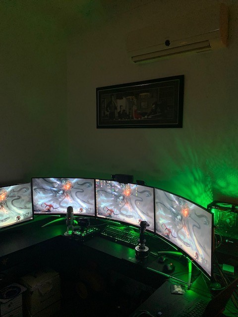
Hi all, I was just wondering if it is possible to have the F-18 HMD come up on the centre of my three monitors and not just the centre monitor. If anyone has done this please give me some instructions to change the UAE file in C++. Regards Mark
-
Hi all, I have the Scratchpad display working ok using a 16x2 display using i2c. https://www.jaycar.com.au/dot-matrix-white-on-blue-lcd-16x2-character/p/QP5521 There are some minor issues that someone might know how to fix. 1/ I have had to move the scratchpadstring2displaychange to 2,0 as it was deleting the string1display if a number was placed into 1,0 such as com select does. This mean that the ON looks like 'O N' and not 'ON'. Also the numbers now look like "10_". 2/ The TCN numer 1 that appears on the right of the scratchpad gets displayed at 12,0 and not 16,0 as the 1 in ILS does. 3? The D/L number 127 appears in 10,0;11,0;12,0 and not 14,0;15,0;16,0. Any workaround suggestion would be greatly appreciated. #define DCSBIOS_DEFAULT_SERIAL #include "DcsBios.h" #include <LiquidCrystal_I2C.h> const int en = 2, rw = 1, rs = 0, d4 = 4, d5 = 5, d6 = 6, d7 = 7, bl = 3; const int i2c_addr = 0x27; LiquidCrystal_I2C lcd(i2c_addr, en, rw, rs, d4, d5, d6, d7, bl, POSITIVE); void onUfcScratchpadString1DisplayChange(char* newValue) { // Print on first row String sNewValue(newValue); sNewValue.replace('~','2'); sNewValue.replace('`','1'); lcd.setCursor(0,0); lcd.print(sNewValue); } DcsBios::StringBuffer<2> ufcScratchpadString1DisplayBuffer(0x5446, onUfcScratchpadString1DisplayChange); void onUfcScratchpadString2DisplayChange(char* newValue) { lcd.setCursor(2,0); lcd.print(newValue); } DcsBios::StringBuffer<2> ufcScratchpadString2DisplayBuffer(0x5448, onUfcScratchpadString2DisplayChange); void onUfcScratchpadNumberDisplayChange(char* newValue) { lcd.setCursor(9,0); lcd.print(newValue); } DcsBios::StringBuffer<8> ufcScratchpadNumberDisplayBuffer(0x543e, onUfcScratchpadNumberDisplayChange); void setup() { lcd.begin(16, 2); lcd.clear(); DcsBios::setup(); } void loop() { DcsBios::loop(); }
-
Help with the U8g2 Library and 128x64 display
Dadzilla74 replied to Dadzilla74's topic in Home Cockpits
Hi all. Challenge completed and all is working fine now. Regards -
Hi All, I worked it out myself. The cueing is for the ":" symbol before the display. I am now working at getting both to display at the same time in a new help thread. Regards Mark
-
Hi Guys, Anyone up for a challenge? I have set up a Duinotech 164x64 Display (https://www.jaycar.com.au/arduino-compatible-128x64-dot-matrix-lcd-display-module/p/XC4617 using the u8g2 library to display a menu from another program (DCSBIOS Library). The issue is that sometime the menu (void onUfcOptionDisplay1Change) item will be selected and a ":" (void onUfcOptionCueing1Change) will be placed before the menu item. For example; abcdefg (not selected) : abcdefg (selected). Each of the voids run fine without the other but placing them together (as per below) I get the rest of the screen blanking out when there is a selection. I understand that this is from the ClearBuffer and nextPage commands. Yet, I hope someone can think of a workaround to keep the menu item on the screen while the selector changes. #define DCSBIOS_IRQ_SERIAL #include "DcsBios.h" #include "U8glib.h" #include <Arduino.h> #include <U8g2lib.h> #ifdef U8X8_HAVE_HW_SPI #include <SPI.h> #endif #ifdef U8X8_HAVE_HW_I2C #include <Wire.h> #endif U8G2_ST7920_128X64_F_SW_SPI u8g2(U8G2_R3, /* clock=*/ 18, /* data=*/ 16, /* CS=*/ 17, /* reset=*/ 13); // Feather HUZZAH ESP8266, E=clock=14, RW=data=13, RS=CS void onUfcOptionCueing1Change(char* newValue) { u8g2.setCursor(0,0); u8g2.setFont(u8g2_font_samim_16_t_all);//u8g2.setFont(u8g_font_5x7); u8g2.clearBuffer(); u8g2.drawStr(15, 25, newValue); } DcsBios::StringBuffer<1> ufcOptionCueing1Buffer(0x5420, onUfcOptionCueing1Change); void onUfcOptionDisplay1Change(char*newValue) { u8g2.setCursor(0,0); u8g2.setFont(u8g2_font_crox3cb_tr);//u8g2.setFont(u8g_font_5x7); u8g2.clearBuffer(); u8g2.drawStr(5, 15, newValue); } DcsBios::StringBuffer<4> ufcOptionDisplay1Buffer(0x542a, onUfcOptionDisplay1Change); void setup() { u8g2.begin(); u8g2.clear(); DcsBios::setup(); } void loop() { onUfcOptionCueing1Change; onUfcOptionDisplay1Change; u8g2.nextPage(); // transfer internal memory to the display DcsBios::loop(); Thanks in advance for any help/comments.
-
Hi Guys, Thanks, I worked it all out myself and is working great now. Regards
-
Could someone please let me know the difference between the F-18C UFCOptionCueing and the UFCOptionDisplay scripts. It is just that there are 5 of each and I am not sure if they are linked or are for completely different displays.
-
more information Hi All, I hope someone can help me out with the loop script as I cannot get the display to show the newValue; I am creating a switch box for my flight sim with several displays. The hardware that I am using is the Arduino Mega and a Duinotech 128x64LCD Dot Matrix which uses the St7920 chip. I also use the U8GLIB library to get the screen working, and then place this Library into the DCS File with the DCSBIOS Library. Currently the pin set up is; GND =GRD VCC = 5V VO = NOT CONNECTED RS = 17 R/W= 16 E = 18 DB0 = 8 DB1 = 9 DB2 = 10 DB3 = 11 DB4 = 4 DB5 = 5 DB6 = 6 DB7 = 7 PSB = GRD NC = NOT CONNECTED RST = NOT CONNECTED VOUT = NOT CONNECTED BLA = 5V BLK = GRD The script I used to test the screen and works fine is; Please remove comment from the constructor of the >>> connected graphics display (see below). Universal 8bit Graphics Library, https://github.com/olikraus/u8glib/ Copyright (c) 2012, olikraus@gmail.com All rights reserved. Redistribution and use in source and binary forms, with or without modification, are permitted provided that the following conditions are met: * Redistributions of source code must retain the above copyright notice, this list of conditions and the following disclaimer. * Redistributions in binary form must reproduce the above copyright notice, this list of conditions and the following disclaimer in the documentation and/or other materials provided with the distribution. THIS SOFTWARE IS PROVIDED BY THE COPYRIGHT HOLDERS AND CONTRIBUTORS "AS IS" AND ANY EXPRESS OR IMPLIED WARRANTIES, INCLUDING, BUT NOT LIMITED TO, THE IMPLIED WARRANTIES OF MERCHANTABILITY AND FITNESS FOR A PARTICULAR PURPOSE ARE DISCLAIMED. IN NO EVENT SHALL THE COPYRIGHT HOLDER OR CONTRIBUTORS BE LIABLE FOR ANY DIRECT, INDIRECT, INCIDENTAL, SPECIAL, EXEMPLARY, OR CONSEQUENTIAL DAMAGES (INCLUDING, BUT NOT LIMITED TO, PROCUREMENT OF SUBSTITUTE GOODS OR SERVICES; LOSS OF USE, DATA, OR PROFITS; OR BUSINESS INTERRUPTION) HOWEVER CAUSED AND ON ANY THEORY OF LIABILITY, WHETHER IN CONTRACT, STRICT LIABILITY, OR TORT (INCLUDING NEGLIGENCE OR OTHERWISE) ARISING IN ANY WAY OUT OF THE USE OF THIS SOFTWARE, EVEN IF ADVISED OF THE POSSIBILITY OF SUCH DAMAGE. */ #include "U8glib.h" U8GLIB_ST7920_128X64_1X u8g(18, 16, 17); // SPI Com: SCK = en = 18, MOSI = rw = 16, CS = di = 17 // setup u8g object, please remove comment from one of the following constructor calls // IMPORTANT NOTE: The following list is incomplete. The complete list of supported // devices with all constructor calls is here: https://github.com/olikraus/u8glib/wiki/device //U8GLIB_ST7920_128X64_1X u8g(8, 9, 10, 11, 4, 5, 6, 7, 18, 17, 16); // 8Bit Com: D0..D7: 8,9,10,11,4,5,6,7 en=18, di=17,rw=16 //U8GLIB_ST7920_128X64_4X u8g(8, 9, 10, 11, 4, 5, 6, 7, 18, 17, 16); // 8Bit Com: D0..D7: 8,9,10,11,4,5,6,7 en=18, di=17,rw=16 //U8GLIB_ST7920_128X64_1X u8g(18, 16, 17); // SPI Com: SCK = en = 18, MOSI = rw = 16, CS = di = 17 //U8GLIB_ST7920_128X64_4X u8g(18, 16, 17); // SPI Com: SCK = en = 18, MOSI = rw = 16, CS = di = 17 //U8GLIB_ST7920_192X32_1X u8g(8, 9, 10, 11, 4, 5, 6, 7, 18, 17, 16); // 8Bit Com: D0..D7: 8,9,10,11,4,5,6,7 en=18, di=17,rw=16 //U8GLIB_ST7920_192X32_4X u8g(8, 9, 10, 11, 4, 5, 6, 7, 18, 17, 16); // 8Bit Com: D0..D7: 8,9,10,11,4,5,6,7 en=18, di=17,rw=16 //U8GLIB_ST7920_192X32_1X u8g(18, 16, 17); // SPI Com: SCK = en = 18, MOSI = rw = 16, CS = di = 17 //U8GLIB_ST7920_192X32_4X u8g(18, 16, 17); // SPI Com: SCK = en = 18, MOSI = rw = 16, CS = di = 17 //U8GLIB_ST7920_192X32_1X u8g(13, 11, 10); // SPI Com: SCK = en = 13, MOSI = rw = 11, CS = di = 10 //U8GLIB_ST7920_192X32_4X u8g(10); // SPI Com: SCK = en = 13, MOSI = rw = 11, CS = di = 10, HW SPI //U8GLIB_ST7920_202X32_1X u8g(8, 9, 10, 11, 4, 5, 6, 7, 18, 17, 16); // 8Bit Com: D0..D7: 8,9,10,11,4,5,6,7 en=18, di=17,rw=16 //U8GLIB_ST7920_202X32_4X u8g(8, 9, 10, 11, 4, 5, 6, 7, 18, 17, 16); // 8Bit Com: D0..D7: 8,9,10,11,4,5,6,7 en=18, di=17,rw=16 //U8GLIB_ST7920_202X32_1X u8g(18, 16, 17); // SPI Com: SCK = en = 18, MOSI = rw = 16, CS = di = 17 //U8GLIB_ST7920_202X32_4X u8g(18, 16, 17); // SPI Com: SCK = en = 18, MOSI = rw = 16, CS = di = 17 void draw(void) { // graphic commands to redraw the complete screen should be placed here u8g.setFont(u8g_font_5x7); //u8g.setFont(u8g_font_5x7); u8g.drawStr( 0, 22, "TEST"); u8g.drawStr( 0, 42, "NOW WORKING"); } void setup(void) { // flip screen, if required // u8g.setRot(); u8g.setRot270() // set SPI backup if required //u8g.setHardwareBackup(u8g_backup_avr_spi); // assign default color value ;if ( u8g.getMode() == U8G_MODE_R3G3B2 ) { u8g.setColorIndex(255); // white } else if ( u8g.getMode() == U8G_MODE_GRAY2BIT ) { u8g.setColorIndex(3); // max intensity } else if ( u8g.getMode() == U8G_MODE_BW ) { u8g.setColorIndex(1); // pixel on } else if ( u8g.getMode() == U8G_MODE_HICOLOR ) { u8g.setHiColorByRGB(255,255,255); } pinMode(8, OUTPUT); } void loop(void) { // picture loop u8g.firstPage(); do { draw(); } while( u8g.nextPage() ); // rebuild the picture after some delay //delay(50); } I have then taken the information from the above code and placed it in my DCS Bios script like; Tell DCS-BIOS to use a serial connection and use interrupt-driven communication. The main program will be interrupted to prioritize processing incoming data. This should work on any Arduino that has an ATMega328 controller (Uno, Pro Mini, many others). */ #define DCSBIOS_IRQ_SERIAL #include "DcsBios.h" #include "U8glib.h" U8GLIB_ST7920_128X64_1X u8g(18, 16, 17); // SPI Com: SCK = en = 18, MOSI = rw = 16, CS = di = 17 /* paste code snippets from the reference documentation here */ void onUfcOptionDisplay1Change(char* newValue) { u8g.setFont(u8g_font_5x7); //u8g.setFont(u8g_font_5x7); u8g.drawStr( 0, 22, "newValue from DCS"); } DcsBios::StringBuffer<4> ufcOptionDisplay1Buffer(0x542a, onUfcOptionDisplay1Change); void setup() { // u8g.setRot(); u8g.setRot270(); // set SPI backup if required //u8g.setHardwareBackup(u8g_backup_avr_spi); // assign default color value ;if ( u8g.getMode() == U8G_MODE_R3G3B2 ) { u8g.setColorIndex(255); // white } else if ( u8g.getMode() == U8G_MODE_GRAY2BIT ) { u8g.setColorIndex(3); // max intensity } else if ( u8g.getMode() == U8G_MODE_BW ) { u8g.setColorIndex(1); // pixel on } else if ( u8g.getMode() == U8G_MODE_HICOLOR ) { u8g.setHiColorByRGB(255,255,255); } pinMode(8, OUTPUT); DcsBios::setup(); } void loop (void){ // picture loop u8g.firstPage(); do { draw(); } while( u8g.nextPage() ); // rebuild the picture after some delay //delay(50); DcsBios:: loop(); } Unfortunately There is an issue with the 'draw' line under 'do'. I have tried to modify to the script but cannot seem to get anything working. I have also tried taking the loop out of the first script yet the screen goes blank. Hopefully someone might be able to help with the loop section to get the script working and displaying the 'newValue'.
-
Hi Mag, Thanks for your advice. The script uploads fine now yet it still shows nothing about the UfcOption Display newValue. I think I need a command that loops the 'Void onUfcOptionDisplayChange' Regards Mark