
Dadzilla74
-
Posts
52 -
Joined
-
Last visited
Content Type
Profiles
Forums
Events
Everything posted by Dadzilla74
-
Hi Mag, Thanks I will try that before trying adafruit later today when I am back home. Regards Mark
-
Hi Guys, Does anyone know if the display which uses the St7920 can be used with Adafruit? If so I will try to use adafruit rather than U8Glib.
-
Hi Hans, When uploading the above script I get; expected constructor,destructor, or type conversion before ';' token on DcsBios::loop(); Is there a work around for this error?
-
Also Hans, I tried to take the loop instruction out of the first script and left it; void loop(void) { } after downloading this, i received no text on the screen either.
-
Thanks Magnatilla, Yes the first script works fine, yet the second one does not. I am now trying out the script Hans just posted which has no errors but also no text on the screen.
-
Thanks Hans, That script has no erros which is good yet the screen does not show the newValue.
-
hi all, on my display board, this works good; #include "U8glib.h" U8GLIB_ST7920_128X64_1X u8g(18, 16, 17); // SPI Com: SCK = en = 18, MOSI = rw = 16, CS = di = 17 void draw(void) { // graphic commands to redraw the complete screen should be placed here u8g.setFont(u8g_font_5x7); //u8g.setFont(u8g_font_5x7); u8g.drawStr( 0, 22, "TEST"); u8g.drawStr( 0, 42, "NOw WORKING"); } void setup(void) { // flip screen, if required // u8g.setRot(); u8g.setRot270() // set SPI backup if required //u8g.setHardwareBackup(u8g_backup_avr_spi); // assign default color value ;if ( u8g.getMode() == U8G_MODE_R3G3B2 ) { u8g.setColorIndex(255); // white } else if ( u8g.getMode() == U8G_MODE_GRAY2BIT ) { u8g.setColorIndex(3); // max intensity } else if ( u8g.getMode() == U8G_MODE_BW ) { u8g.setColorIndex(1); // pixel on } else if ( u8g.getMode() == U8G_MODE_HICOLOR ) { u8g.setHiColorByRGB(255,255,255); } pinMode(8, OUTPUT); } void loop(void) { // picture loop u8g.firstPage(); do { draw(); } while( u8g.nextPage() ); // rebuild the picture after some delay //delay(50); } Moving most of this into dcs bios UFC Display looks like this; /* Tell DCS-BIOS to use a serial connection and use interrupt-driven communication. The main program will be interrupted to prioritize processing incoming data. This should work on any Arduino that has an ATMega328 controller (Uno, Pro Mini, many others). */ #define DCSBIOS_IRQ_SERIAL #include "DcsBios.h" #include "U8glib.h" U8GLIB_ST7920_128X64_1X u8g(18, 16, 17); // SPI Com: SCK = en = 18, MOSI = rw = 16, CS = di = 17 /* paste code snippets from the reference documentation here */ void onUfcOptionDisplay1Change(char* newValue) { u8g.setFont(u8g_font_5x7); //u8g.setFont(u8g_font_5x7); u8g.drawStr( 0, 22, "TEST"); } DcsBios::StringBuffer<4> ufcOptionDisplay1Buffer(0x542a, onUfcOptionDisplay1Change); void setup() { // u8g.setRot(); u8g.setRot270(); // set SPI backup if required //u8g.setHardwareBackup(u8g_backup_avr_spi); // assign default color value ;if ( u8g.getMode() == U8G_MODE_R3G3B2 ) { u8g.setColorIndex(255); // white } else if ( u8g.getMode() == U8G_MODE_GRAY2BIT ) { u8g.setColorIndex(3); // max intensity } else if ( u8g.getMode() == U8G_MODE_BW ) { u8g.setColorIndex(1); // pixel on } else if ( u8g.getMode() == U8G_MODE_HICOLOR ) { u8g.setHiColorByRGB(255,255,255); } pinMode(8, OUTPUT); DcsBios::setup(); } void loop(void) { // picture loop u8g.firstPage(); do { draw(); } while( u8g.nextPage() ); // rebuild the picture after some delay //delay(50); } DcsBios::loop(); } However there is an error; 'draw' was not declared in this scope. Does anyone know how to fix this issue?
-
Ok, So I have managed to get the text rotated by 90 degrees and can position 5 lines down the screen. I just need to understand what the UFC Cueing is (as I am not sure what this is for and if this is needed for the UFC option display) and a script to tell DCS bios where to place the display for the UFC Option display. If anyone could help it would be greatly appreciated.
-
Hi All, Has anyone set up a 128x64 LCD dot matrix before for DCS BIOS? I have purchased a; https://www.jaycar.com.au/arduino-compatible-128x64-dot-matrix-lcd-display-module/p/XC4617 with a ST7920 chip set. I would like to use this for the 5 x UFC option displays in the f-18C by rotating 90 degrees and spacing out 5 lines. The Arduino board I am using is a Mega Board. There is very little information and the Arduino examples do not seem to suit my purpose. If anyone has some experience with this, it would be greatly appreciated if you could help.
-

What to change Dcs Bios script for slave board
Dadzilla74 replied to Dadzilla74's topic in Home Cockpits
Thanks Hans, This looks like a great starting point and has given me some confidence that I should be able to get this working. It will be a couple of weeks before I continue to work on this and I will let you know how I get on. -
What to change Dcs Bios script for slave board
Dadzilla74 replied to Dadzilla74's topic in Home Cockpits
Hi Hans, I did see one of your threads where you have 3 Arduino Micro's set up to your Arduino Mega. I would just like to know the difference in script. For example if you are setting up the Altitude Switch to pins 8 and 9, the script would look like; DcsBios::Switch2Pos hudAltSw("HUD_ALT_SW", PIN); What would the script look like if it was on the same pins but on the Micro 1 board and then again on the Micro 2 board? -
What to change Dcs Bios script for slave board
Dadzilla74 replied to Dadzilla74's topic in Home Cockpits
Thanks Hans and Smill, I will look into these both. I do agree Hans with the two USB ports being used but thought there might be an easier style to piggy back them onto on another and most cockpit makeouts would need load of USB ports to hook it all up. -
Hi All, Just thinking of adding a slave Arduino Mega to my Existing Mega. Could someone please let me know how to change the DCS-Bios script to account for this? For example, if I would like to setup the Brightness Control Knob onto pin A3 Slave I could not use; DcsBios::Potentiometer ampcdBrtCtl("AMPCD_BRT_CTL", A3); as this would be the master board. I need to know how I change the script. Thanks
-
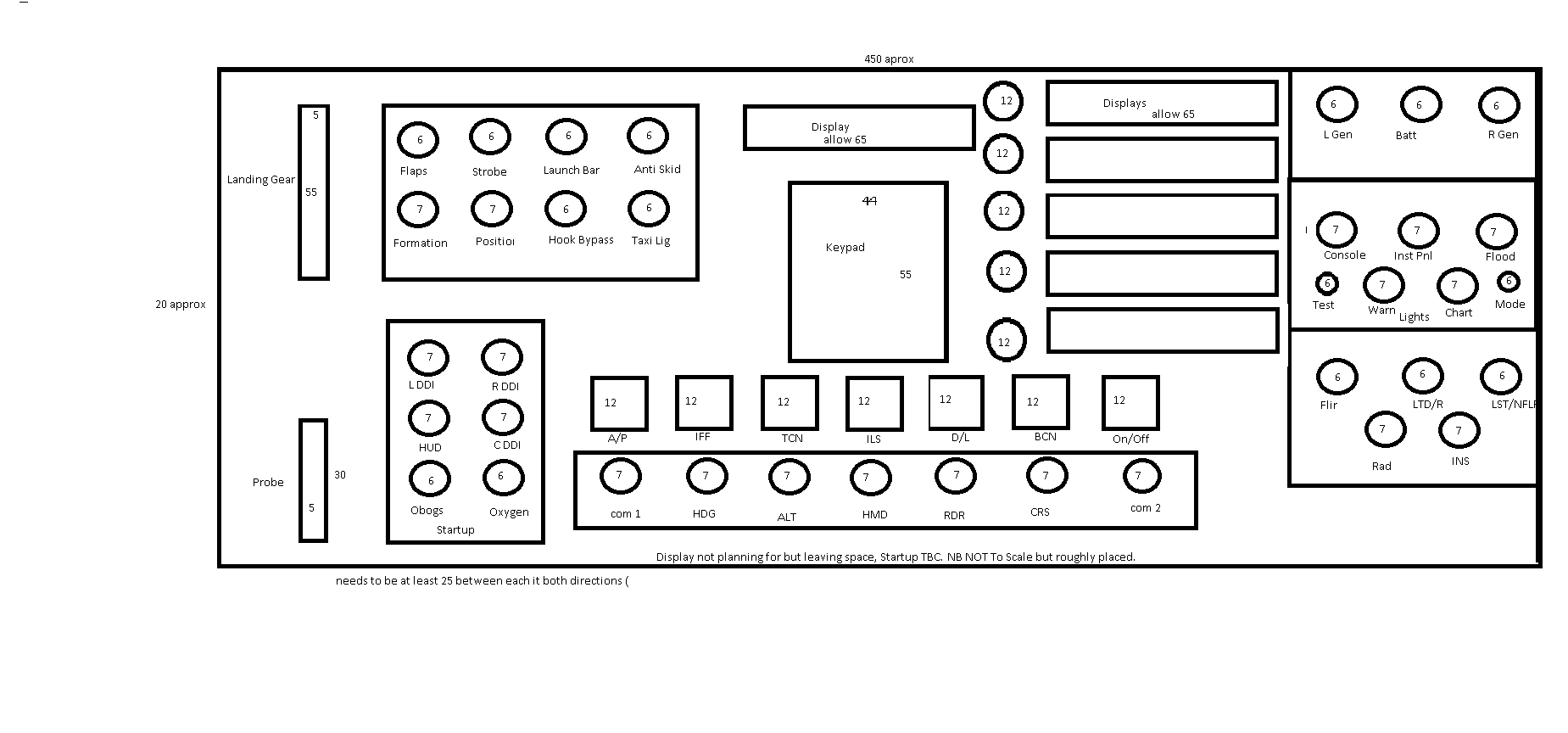
Hi all, Just wanted to see what option people think I should use as an LCD display for the 5 vertical panels in the DCS F-18C. Just want to know if a large one behind could be used or if I would need 5 separate ones.

-
Arduino Mega not communicating with DCS Bios
Dadzilla74 replied to Dadzilla74's topic in Home Cockpits
Thanks again Hans, You have done it again and all works fine. Thanks so much. For others, my script is here; /* Tell DCS-BIOS to use a serial connection and use interrupt-driven communication. The main program will be interrupted to prioritize processing incoming data. This should work on any Arduino that has an ATMega328 controller (Uno, Pro Mini, many others). */ #define DCSBIOS_IRQ_SERIAL #define TXENABLE_PIN 2 #include <Keypad.h> #include "DcsBios.h" /* paste code snippets from the reference documentation here */ DcsBios::Switch2Pos fcsResetBtn("FCS_RESET_BTN", A1); DcsBios::Switch2Pos lGenSw("L_GEN_SW", 24); DcsBios::Switch3Pos batterySw("BATTERY_SW",26, 28); DcsBios::RotaryEncoder radaltHeight("RADALT_HEIGHT", "-3200", "+3200", A1, A3); const byte ROWS = 4; //four rows const byte COLS = 3; //three columns char keys[ROWS][COLS] = { {'1','2','3'}, {'4','5','6'}, {'7','8','9'}, {'*','0','#'}, }; byte rowPins[ROWS] = {3, 8, 7, 5}; //connect to the row pinouts of the keypad byte colPins[COLS] = {4, 2, 6}; //connect to the column pinouts of the keypad Keypad keypad = Keypad( makeKeymap(keys), rowPins, colPins, ROWS, COLS ); void setup() { DcsBios::setup(); keypad.addEventListener(keypadEvent); // Add an event listener. keypad.setHoldTime(100); // Default is 1000mS keypad.setDebounceTime(50); // Default is 50mS } void loop() { DcsBios::loop(); char key = keypad.getKey(); } void keypadEvent(KeypadEvent KEY){ switch (keypad.getState()) { // gives PRESSED, HOLD or RELEASED case PRESSED: switch(KEY) { // UFC case '1': sendDcsBiosMessage("UFC_1", "1"); break; case '2': sendDcsBiosMessage("UFC_2", "1"); break; case '3': sendDcsBiosMessage("UFC_3", "1"); break; case '4': sendDcsBiosMessage("UFC_4", "1"); break; case '5': sendDcsBiosMessage("UFC_5", "1"); break; case '6': sendDcsBiosMessage("UFC_6", "1"); break; case '7': sendDcsBiosMessage("UFC_7", "1"); break; case '8': sendDcsBiosMessage("UFC_8", "1"); break; case '9': sendDcsBiosMessage("UFC_9", "1"); break; case '0': sendDcsBiosMessage("UFC_0", "1"); break; case '*': sendDcsBiosMessage("UFC_CLR", "1"); break; case '#': sendDcsBiosMessage("UFC_ENT", "1"); break; }} switch (keypad.getState()){ // gives PRESSED, HOLD or RELEASED case RELEASED: // LMFD switch(KEY) { // Released OSBs or Neutral Rockers signal is sent case '1': sendDcsBiosMessage("UFC_1", "0"); break; case '2': sendDcsBiosMessage("UFC_2", "0"); break; case '3': sendDcsBiosMessage("UFC_3", "0"); break; case '4': sendDcsBiosMessage("UFC_4", "0"); break; case '5': sendDcsBiosMessage("UFC_5", "0"); break; case '6': sendDcsBiosMessage("UFC_6", "0"); break; case '7': sendDcsBiosMessage("UFC_7", "0"); break; case '8': sendDcsBiosMessage("UFC_8", "0"); break; case '9': sendDcsBiosMessage("UFC_9", "0"); break; case '0': sendDcsBiosMessage("UFC_0", "0"); break; case '*': sendDcsBiosMessage("UFC_CLR", "0"); break; case '#': sendDcsBiosMessage("UFC_ENT", "0"); break; }} } -
Arduino Mega not communicating with DCS Bios
Dadzilla74 replied to Dadzilla74's topic in Home Cockpits
Thanks Hans, Do I place the script for this matrix within; /* Tell DCS-BIOS to use a serial connection and use interrupt-driven communication. The main program will be interrupted to prioritize processing incoming data. This should work on any Arduino that has an ATMega328 controller (Uno, Pro Mini, many others). */ #define DCSBIOS_IRQ_SERIAL #include "DcsBios.h" /* paste code snippets from the reference documentation here */ DcsBios::Switch2Pos fcsResetBtn("FCS_RESET_BTN", A1); DcsBios::Switch2Pos lGenSw("L_GEN_SW", 24); DcsBios::Switch3Pos batterySw("BATTERY_SW",26, 28); DcsBios::RotaryEncoder radaltHeight("RADALT_HEIGHT", "-3200", "+3200", A1, A3); void setup() { DcsBios::setup(); } void loop() { DcsBios::loop(); } Or can I enter the script below my current script? -
Arduino Mega not communicating with DCS Bios
Dadzilla74 replied to Dadzilla74's topic in Home Cockpits
Hi Guys, Next issue. Keypad Script. The current DCS-Bios Script is; DcsBios::Switch2Pos ampcdPb01("AMPCD_PB_01", Pin); Given that I am using a 3x4 matrix key pad, is there a script that can be used in place of this? I have looked at some of the other threads and watched the clip on how the matrix works and can understand that. The keypad I an using is; https://www.jaycar.com.au/12-key-numeric-keypad/p/SP0770 and have the pinout in ports 2-8 in the Arduino mega boards. Any help will be great appreciated. Regards Mark -
Arduino Mega not communicating with DCS Bios
Dadzilla74 replied to Dadzilla74's topic in Home Cockpits
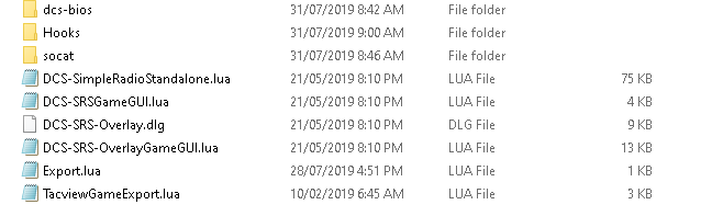
Ok Guys, I would just like to say thanks to Hans, Presta, Muts and smill for your comments and help. This issue has now been worked out as I looked in the DCS logs and found an issue where some of the dcs bios such as the Lib, doc, Bios.lau and Biosconfig files for the f-18 were located. In short they were located in the dcs/scripts/dcs-bios/scripts/dcs-bios After looking at the log I noticed that dcs was looking in; user/savedgames/dcs/script I them moved all the files from dcs/scripts/dcs-bios/scripts/dcs-bios and placed them in user/savedgames/dcs/script The waterflow is now flowing and my button works in the F-18 cockpit. Again a great big thank you to all that helped. -
Arduino Mega not communicating with DCS Bios
Dadzilla74 replied to Dadzilla74's topic in Home Cockpits
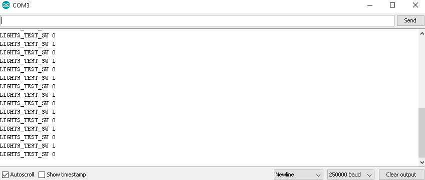
Hi Hans (and Presta) Little closer now as the error has gone yet the waterfall does not flow and just get a cursor after the countdown. Text does appear when I press the button; And the button does not work in the cockpit.
-
Arduino Mega not communicating with DCS Bios
Dadzilla74 replied to Dadzilla74's topic in Home Cockpits
Hi Hans, sure; local dcsSr=require('lfs');dofile(dcsSr.writedir()..[[scripts\DCS-SimpleRadioStandalone.lua]]) local Tacviewlfs=require('lfs');dofile(Tacviewlfs.writedir()..'Scripts/TacviewGameExport.lua') dofile(lfs.writedir()..[[scripts\DCS-BIOS\BIOS.lua]]) -
Arduino Mega not communicating with DCS Bios
Dadzilla74 replied to Dadzilla74's topic in Home Cockpits
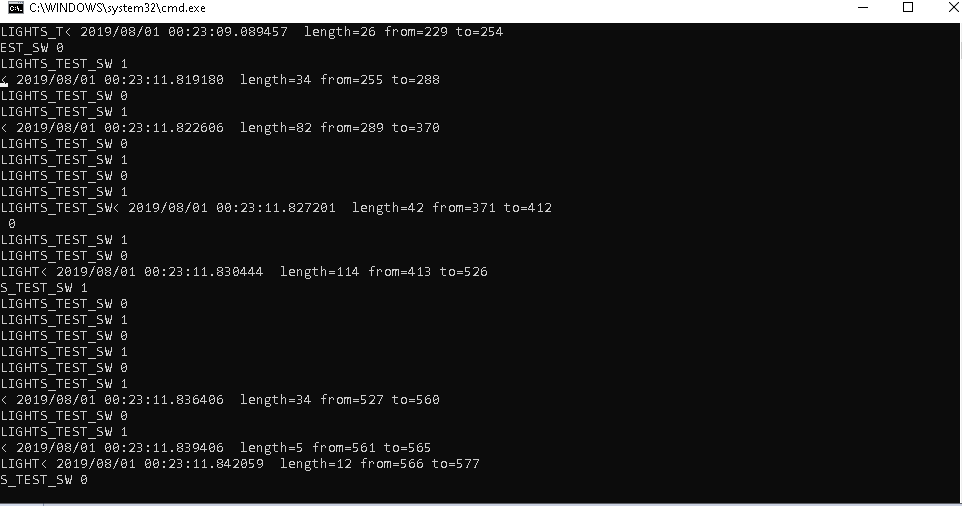
Hi Muts, Thanks. Yes DCS is running and unpaused. I get the following from the monitor;
-
Arduino Mega not communicating with DCS Bios
Dadzilla74 replied to Dadzilla74's topic in Home Cockpits
Hi Hans, Thanks, I am using the F-18. Script file looks like I dont get the waterfall which is what I am trying to do. I get the error message I am using the Mega Board and not the uno, yet I can get the led program to work (using the led on the board) the issue is that the connect-serial-port program will not work.
-
Arduino Mega not communicating with DCS Bios
Dadzilla74 replied to Dadzilla74's topic in Home Cockpits
Hi Smill, As I stated in the first message, this ones works fine; /* Blink Turns an LED on for one second, then off for one second, repeatedly. Most Arduinos have an on-board LED you can control. On the UNO, MEGA and ZERO it is attached to digital pin 13, on MKR1000 on pin 6. LED_BUILTIN is set to the correct LED pin independent of which board is used. If you want to know what pin the on-board LED is connected to on your Arduino model, check the Technical Specs of your board at: https://www.arduino.cc/en/Main/Products modified 8 May 2014 by Scott Fitzgerald modified 2 Sep 2016 by Arturo Guadalupi modified 8 Sep 2016 by Colby Newman This example code is in the public domain. http://www.arduino.cc/en/Tutorial/Blink */ // the setup function runs once when you press reset or power the board void setup() { // initialize digital pin LED_BUILTIN as an output. pinMode(LED_BUILTIN, OUTPUT); } // the loop function runs over and over again forever void loop() { digitalWrite(LED_BUILTIN, HIGH); // turn the LED on (HIGH is the voltage level) delay(1000); // wait for a second digitalWrite(LED_BUILTIN, LOW); // turn the LED off by making the voltage LOW delay(1000); // wait for a second } Which means that I can communicate to the board. The issue is that the board will not communicate to the computer. -
Arduino Mega not communicating with DCS Bios
Dadzilla74 replied to Dadzilla74's topic in Home Cockpits
Thanks Hans, /* Tell DCS-BIOS to use a serial connection and use interrupt-driven communication. The main program will be interrupted to prioritize processing incoming data. This should work on any Arduino that has an ATMega328 controller (Uno, Pro Mini, many others). */ #define DCSBIOS_IRQ_SERIAL #include "DcsBios.h" /* paste code snippets from the reference documentation here */ DcsBios::Switch2Pos lightsTestSw("LIGHTS_TEST_SW", 22); void setup() { DcsBios::setup(); } void loop() { DcsBios::loop(); } Just using this as a start. -
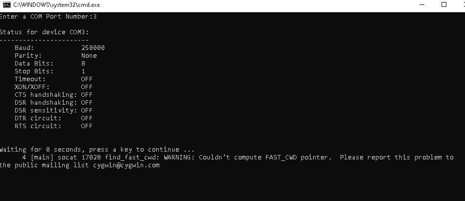
Hi All, I have just started a project to build a switch box for DCS. After purchasing the Arduino Mega, I am able to upload a script using port 3 such as the "Blink" script and works fine. I have also connected a button that can be held to on then released to off and uploaded a script to use that button to turn on and off the light on the Mega board (same as used in the "Blink script". This shows that I can communicate with the Mega. After Downloading the DSC Bios software. I get the following warning when I try to connect the mega to DCS BIOS using connect-serial-port.cdm; WARNING: Couldn't compute FAST_CWD pointer. Please report this problem to the public mailing list cygwin@cygwin.com This warning starts with; 5 [main] socat 13340 find_fast_cwd: Yet the value in this line change. Dcs-beta is running at the time I try to connect(not on pause) and the mega is plugged in. I have trying changing ports, changing baud rates and even taken out the tcp line in the BIOCong.lau (as I found some of these fixes online) to no avail. I am running windows 10 v 1903 and have looked everywhere online and on youtube for the fix to again, no avail. Unfortunately, This sort of thing is not my area of expertise but trying very hard to learn quickly. Any detailed help would be greatly appreciated.