rosariovw
-
Posts
7 -
Joined
-
Last visited
-
I got almost all my panels done, but due to the problems with my rs485, i going to stop and start selling my parts. ATM i got it all working with standard USB connections, but now i'm at 40USB cables.
-
Sorry, doesn't help, still i have no data flow from the slave
-
Here are my scripts: Master; /* Tell DCS-BIOS this is a RS-485 Master. You will need to flash this to a Mega 2560. */ #define DCSBIOS_RS485_MASTER /* Define where the TX_ENABLE signals are connected. You can connect up to three half-duplex RS-485 transceivers. Arduino Pin RS-485 Transceiver Pin TXn ------------------- DI (driver input) RXn ------------------- RO (Receiver Output) UARTn_TXENABLE_PIN ---- /RE, DE (active low receiver enable, driver enable) If you have less than three transceivers connected, comment out the corresponding #define UARTn_TEXENABLE_PIN lines for receivers that are not present. */ #define UART1_TXENABLE_PIN 2 #include "DcsBios.h" void setup() { DcsBios::setup(); } void loop() { DcsBios::loop(); } Slave; /* The following #define tells DCS-BIOS that this is a RS-485 slave device. It also sets the address of this slave device. The slave address should be between 1 and 126 and must be unique among all devices on the same bus. */ #define DCSBIOS_RS485_SLAVE 1 /* The Arduino pin that is connected to the /RE and DE pins on the RS-485 transceiver. */ #define TXENABLE_PIN 2 #include "DcsBios.h" /* paste code snippets from the reference documentation here */ DcsBios::Switch2Pos pltHudDeclutter("PLT_HUD_DECLUTTER", 4); DcsBios::LED pltWarnLadder(0x12dc, 0x8000, 13); void setup() { DcsBios::setup(); } void loop() { DcsBios::loop(); }
-
Hey guys, i have trouble with my RS485 connection. I'm trying to get it sorted out for 2 weeks now. To start, if i connect a mega and a Uno the Rx light flashes on both boards. When i put an LED in the A and B i got flashing. So there is some data flowing. I made a sketch with the ladder light at pin 13 (for the F-14) and even that one doesn't light on the UNO. Second part is a switch, and even if i press it, there is no response on DCS. Any tips, cause i'm at the verge of going to straight USB connections via USB Hub. This is the first problem i have the second is, i don't get my 3pos switches working
-
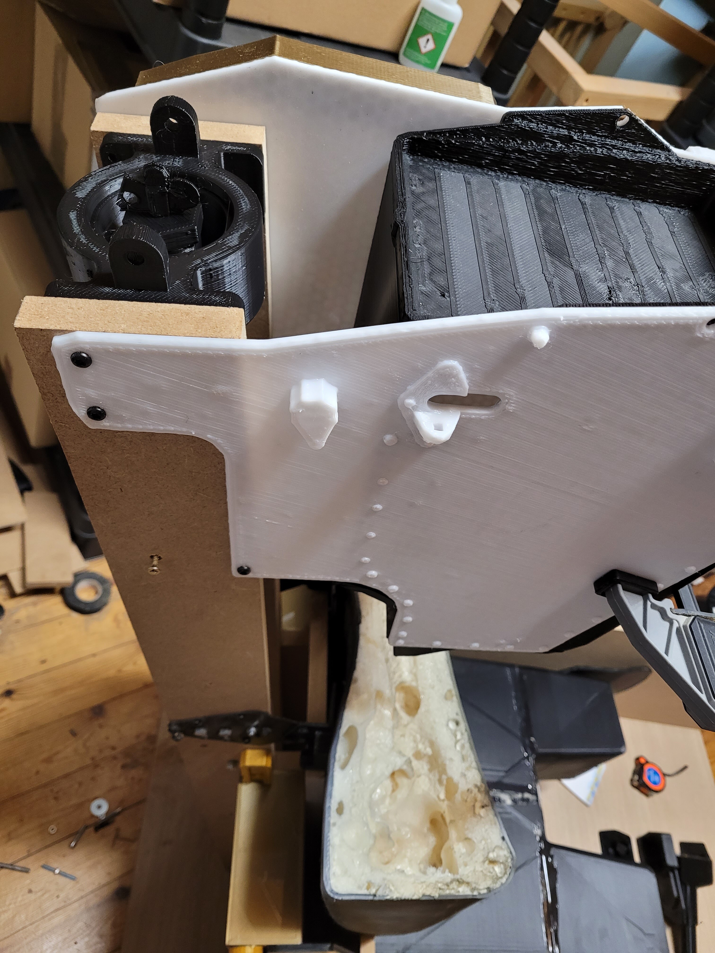
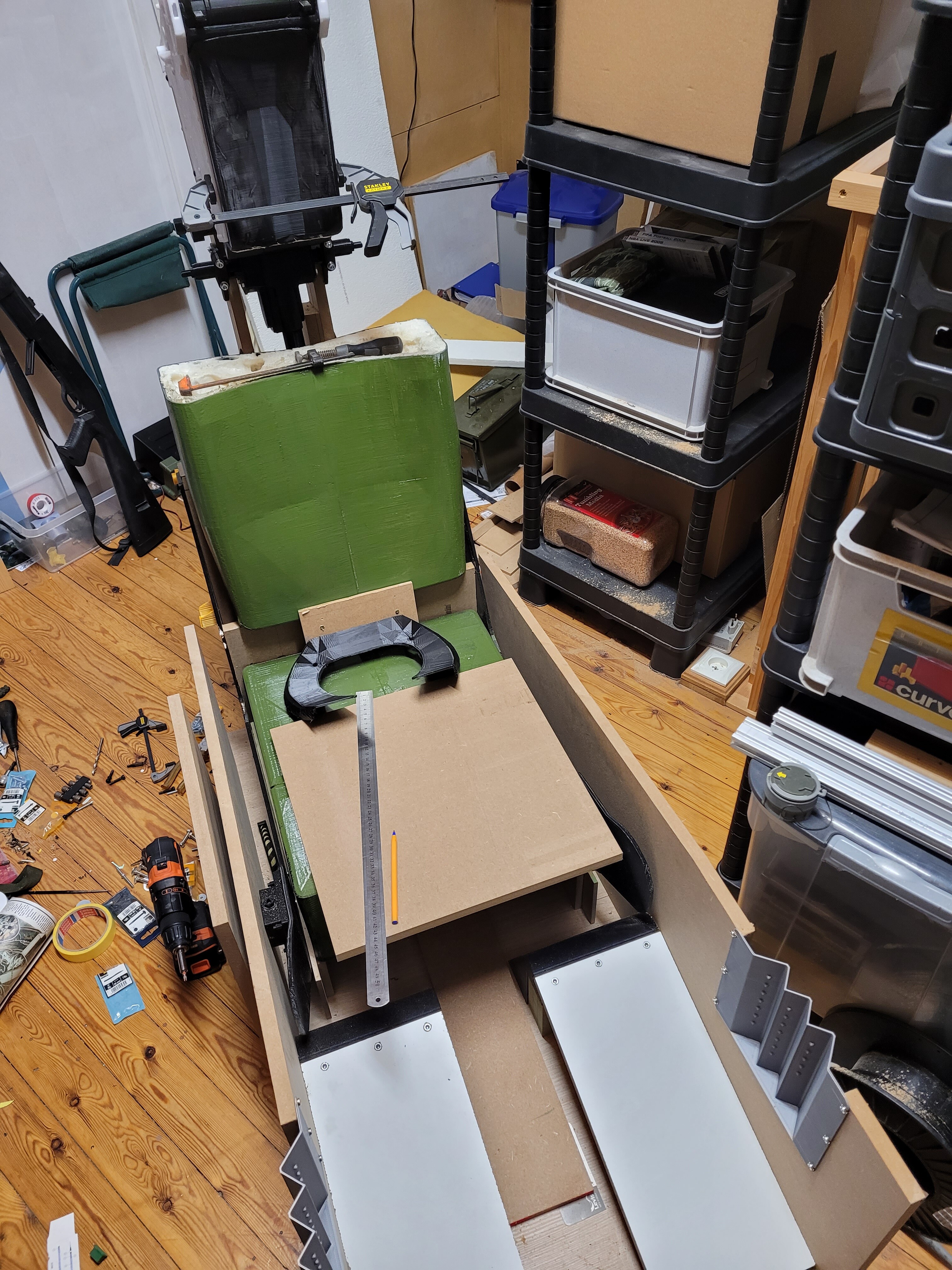
At the moment i made some progress by 3d printing and MDF parts, here is my progress. Already got 12kg filament used, and bought another 8kg more

-
Here is my first 4 parts to make the Survical box (seat pan) These are STL files an can be printed, but be aware, thse are big parts. Surbox4.stl Surbox3.stl Surbox2.stl Surbox1.stl
-
Hello, i'm new here. I own the game from the start but ATM i did only do 4h of playing the game for now. I'm working on a 3d version of the pit, a combination of the 3D file and some rework in CAD. I will be making my pit by 3d printing in modules. I have a 3d printer with a printing size of 40x40x36. Also i have a 3060 cnc machine. I love to see how it all evolves here, everyone is doing a great job, and lovely to see the different approches.