SirioAstarot
-
Posts
5 -
Joined
-
Last visited
Content Type
Profiles
Forums
Events
Everything posted by SirioAstarot
-
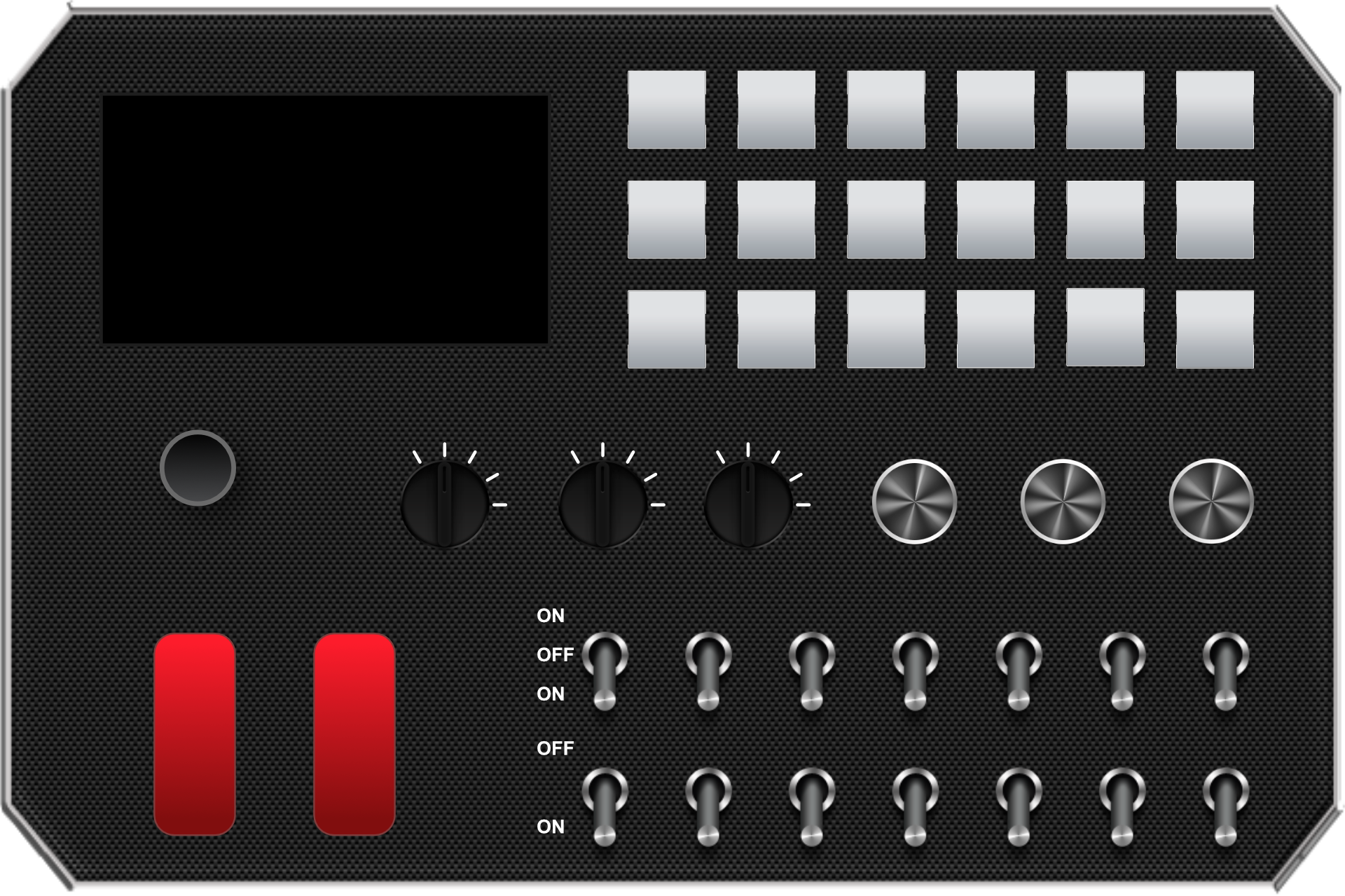
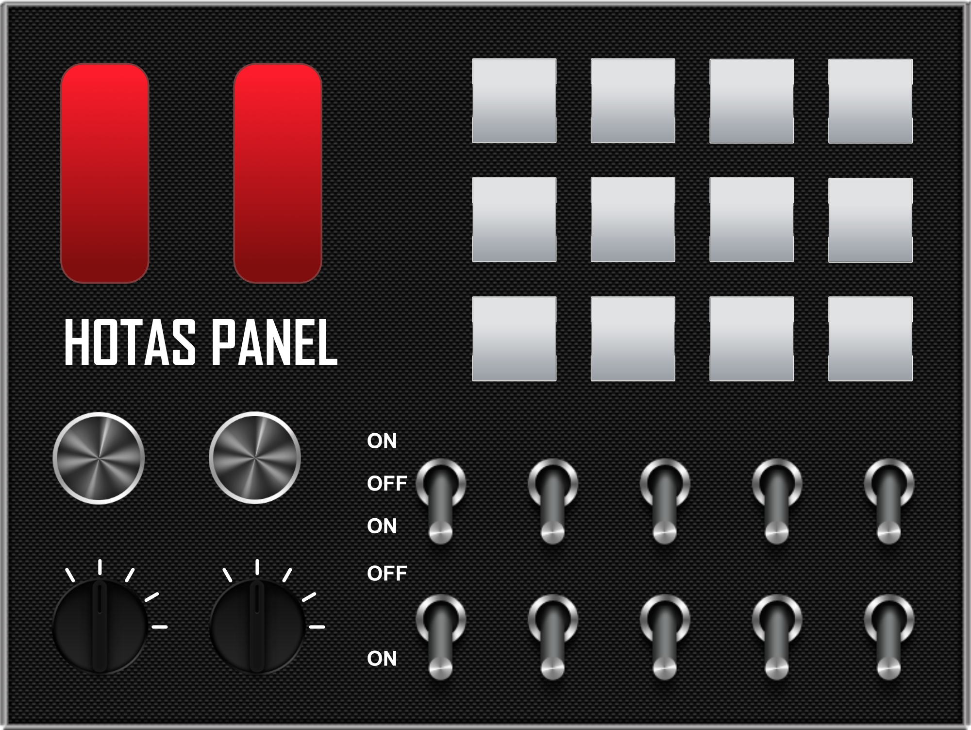
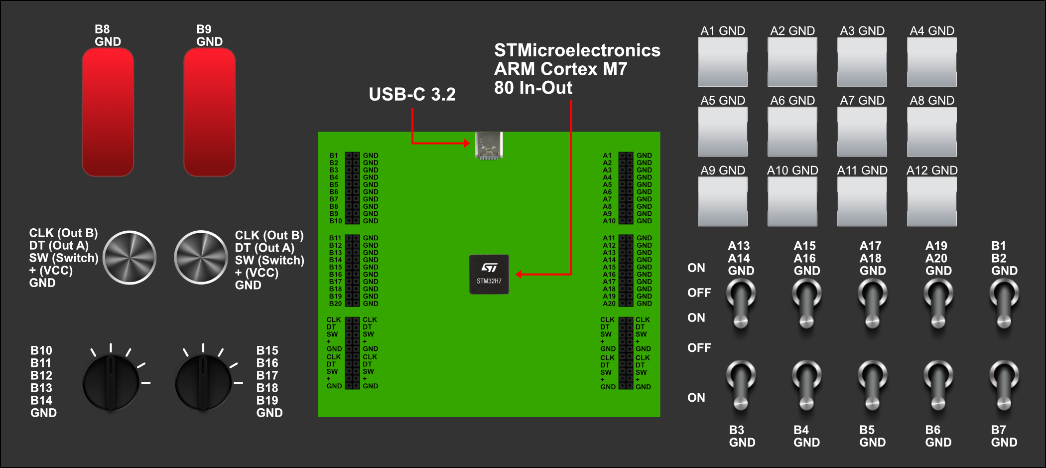
I changed my mind, I have searched a lot about MCUs and the types of signals and protocols they support, there are some that are easy to program like the ESP32 supported by Arduino IDE, like SAMV7 or STM32, but there are other environments like Flowcode and MATLAB, which is what I am using, to dump code in C++ or directly to the device. But I have a problem, the development boards are too small and the big ones are complicated because they have jack connectors for power supply, USB 2, ethernet, and the connection pins are combined, there are no development board models on the market that have exclusive pins. In addition to buying cables and a soldering iron to do everything myself, so I am forced to send the Geber file to an assembler with the design made by me. Here I have a sample of my own peripheral for my flight simulator, the most complete possible. This allows me to reduce production costs and simplify development, have a single design for all the device's functions, use them in a personalized way, with buttons, switches and switches that are fully assignable by the user, in any simulation video game, be it DCS, Elite Dangerous or MSFS24. The microcontroller chosen to complete this type of design in the schematic is the following: STM32H757XI Dual core ARM Cortex M7 and M4 2MB Flash Memory 168 GPIO 4 types internal oscilators Digital: 4x I2C, 5x USART, 4x SAI, 2x USB OTG, HDMI Analog: 3x ADC 16 bits, 2x DAC 12 bits, 2× ultra-low-power comparators, 2× operational amplifiers, 1× digital filters for sigma delta modulator (DFSDM) with 8 channels/4 filters LCD-TFT controller 1024x768px, 256 colours With all these features I can have the flexibility to program any HOTAS similar to those of the competition, even far exceeding the functions available on the market, achieving maximum performance without compromising reliability, even incorporating a 3.5" XGA display to view coordinates, or VHF frequencies or any data with 85x38 characters. The possibilities that this versatile MCU will allow me to achieve are beyond the budget of casual gamers, even for DCS or MSFS24, it could be more intended for Prepar3D v6 and flight schools. But oh well, What do you think, would you buy a peripheral like this? How much are you willing to spend for this semi-pro equipment? I accept changes or suggestions. My best regards.

-
I am interested in purchasing this new gear, but my desk is quite small. Could you tell me what its complete dimensions are?
-
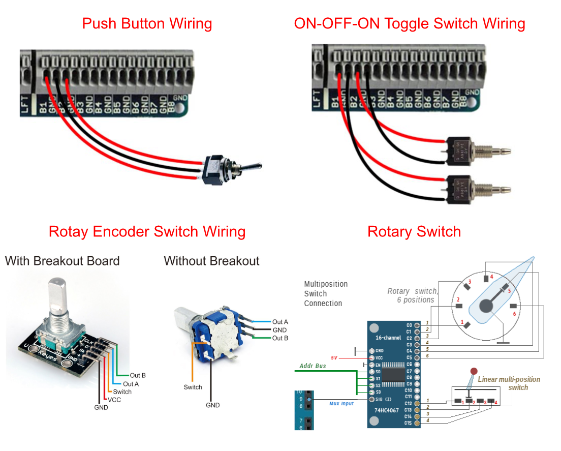
Hi Nightdare, the Leo Bodnar BBI-64 Button Box Interface It's simple to get started with, but it's a HID device, so it only supports digital buttons, it doesn't allow me to communicate directly with the device, so I need a controller to assign it the functions I need, for example, having a button light up when I press it. Hi Scott, My choice of Arduino is because I learned to use it in my career, it is what I know how to use, not only in programming, but also in simulation, I do the entire environment in MATLAB and Simulink for development, testing and simulation before final mass manufacturing. Boards like the Arduino Nano ESP32 with headers with Nano Screw Terminal Adapter or any other compatible base adapter (to add more components in the future), allow me to design a bidirectional communication interface, which when pressing a backlit button, turns white, as well as design a screen that displays numbers and other data. My project is based on a control panel for flight simulators, not only for DCS but also for other air combat, space and civil flight simulators, such as: Elite Dangerous Star Citizen Eve Online Star Conflict No Man’s Sky Everspace 2 Star Wars Eclipse Ace Combat 7 DCS World Microsoft Fligth Simulator 24 X-Plane 12 Project Wingman X4 War Thunder Avorion I was also analyzing several alternatives regarding plates and extensions: Arduino Nano ESP32 with headers with Nano Screw Terminal Adapter Arduino MKR WiFi 1010 with Arduino MKR Connector Carrier Arduino Pro Portenta C33 with Portenta Mid Carrier Custom PCB with several IO and SMTmicroelectronics I will make the connections with male-male jumper wires, to connect them directly, because I don't have a soldering iron. I will take into account your recommendation about the ON-ON-ON switchers, I think they will be better for selectors for example (changing the Com1-Com2-ADF radio), HUD Management Panel, etc... If you say that analog rotary encoders work better I will change them, so they can work better in selecting the radio frequency and other controls when needed.
-
Hi Nightdare, so if the pins are independent, the ground (GND) connections, is it better to count them in series? Is a serial or parallel connection better? I have two options depending on what is easier: Arduino Nano ESP32 with headers with Nano Screw Terminal Adapter Arduino Portenta C33 with Portenta Mid Carrier I'm not sure if the Shields are enough or too many, Is it safe to make serial connections?
-
Good morning virtual pilots, I have a personal project and I would like to know your opinions and if what I am doing is possible. The project is in the planning phase, with the idea of building a control panel for different flight simulators, based on Arduino, the development is designed to be versatile, complete and compatible with all flight simulators, both civil and military, air combat and radio. For this to be possible, I can do 2 options that I am determined to build, depending on the difficulty. - 1st Option: An Arduino Nano ESP32 with headers and matrix connection. - 2nd Option: Design a PCB with a microcontroller and pins for the connection of the components, together with their corresponding GND output. Layout Wiring For the second option, the layout It consists of independently connecting all the pins, together with their corresponding ground (GND): Pins and wiring (include GND) ON-OFF Toggle Switch: 7 x 2pin = 16 Pin IN ON-OFF-ON Toggle Switch: 7 x 3pin = 21 pin IN Pushbutton: 12 x 2pin = 24 pin IN Rotary Encoders with push button: 3 x 2 pin = 6 pin IN Rotary Switches 5 Pos: 2 x 6pin = 12 pin IN Total Pins IN: 79 include GND at each connector. What is better for me, making a connection matrix in Arduino or developing a custom microcontroller for the independent connections?