

geneb
-
Posts
198 -
Joined
-
Last visited
Content Type
Profiles
Forums
Events
Posts posted by geneb
-
-
Ah, very cool. You're not using any screen warping software, correct?
I wonder how practical a rear-projection setup would be given the dimensions I'd have to work with (minimum would be 10' to a side I think)
g.
-
That's what I suspected. This may just be the method I need to use with the F-15 because it's too big to build a "standard" (non-bugeye) collimated display around.
Have you considered putting your cockpit up on a riser that will get you up off the floor a few feet?
g.
-
That setup looks really good guys. Great job!
Keep in mind that when you're comparing your DIY rig to the commercial systems, often times the commercial display is using a polygon shaped "bug eye" that's collimated. This is how the F-15 flight sim visuals are done by L3. The static photos you see of them don't show how good they look when your head is in the right spot.
Flim, your video shows a visual "wrap" as things cross the corner of the display box - is this an actual visual issue or is it an artifact of the video recording process you're using?
g.
-
avlolga, your best bet is to hit http://www.arduino.cc and find a local supplier and get one. It's basically a tiny little board based on the ATMega328 microcontroller. You talk to it via a built-in USB serial interface. I've seen various Arduino compatible setups for as little as $12. The Centipede Shield (add-on boards for the Arduino are called "shields". They stack on top of the Arudino board itself) is available from Macetech - http://www.macetech.com
g.
-
Airdog, that's pretty damn cool. Great setup!
DEChengst: Yes, but it only did it *once*. :D
All joking aside, the pilot lost his life in a similar accident in an F-16 for the same reason - Overcome By Events. Basically, the aircraft got ahead of him and he never caught up in time. I was able to get the "releasable" portion of the accident report for '007 and there was _nothing_ mechanically wrong with that bird, other than maybe a lingering "seafood" smell. :) (Way OT: Did you know that running a VAX 8250 with four RA81 drives can make your whole house vibrate? :D) )
Here's a video I did last week on the board I'm going to be using to drive the MCP and other incandescent displays:
Has anyone else on this forum been working on an F-15 cockpit?
Oh, there's actually TWO of us now. A friend of mine got his hands on the cockpit section (with canopy!) of an A model that was living at Seymour-Johnson AFB for years being used as an ABDR trainer.
g.
-
i want the F-15C A2G capabiliities , (at least of the Israeli one) included
Never a pound for air to ground! :)
The software for A2G was removed at or before MSIP II (Multi Stage Improvement Program, Phase II).
If you want to blow up what's down and shoot down what's up, get yourself a Mudhen. :D
g.
-
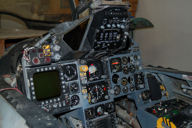
Does this count? :D

g.
-
Ok, I've just posted a corrected version of the files. This includes the dogbone errors that Wayne found (Thanks!) as well as getting the leg-length of that one 6mm part fixed.
The new file can be had here:
http://www.geneb.org/a10/optimized-wharthog-12oct11.zip
g.
-
Gene,
Thanks for your kind help to the pit builders in your area. Time only cncing is a great value for a quick pit build. Wish I was closer, but Texas does it for me.
Lumper, take a peek here:
http://www.100kgarages.com/fabbers/map
There looks to be a few fabbers near Ft. Worth that you could use.
g.
-
That's a nice little machine. I don't know what panel dimensions you're referring to however.
g.
-
 1
1
-
-
BTW, for those of you that are in the Pacific Northwest, I would be happy to cut these plans out for you. I only charge for time & materials. Time only if you bring the material. (Yes, you can watch it be cut if you want. :D )
If you're NOT in the Pacific Northwest, please hit the 100kgarages.com site to try to find a ShopBotter or other CNC router user in your area. Trust me, you do NOT want to pay freight on the weight of 3 sheets of 12mm, one sheet of 6mm and about an eighth sheet of 18mm. :)
g.
-
Henk, there are no dimensions in the files I provided. The files I provided are optimized for material usage for cutting by CNC machine. Jedi's original drawings contain dimensions suitable for hand layout and can be opened with DraftSight.
g.
-
Thanks again g
You're quite welcome! Happy to do it.
g.
-
-
Ok, here's the file:
http://www.geneb.org/a10/optimized-wharthog-v2.zip
This file contains DXF files split by material thickness and optimized for cutting from a 4x8 sheet using a 5mm cutter.
I've also included the VCarve Pro files that were used in the material optimization step. I decided against providing any tool paths as individual operators have their own way of doing things and can easily generate the tool paths for their machines the they want.
Enjoy!
g.
-
For those that want to see what the drawings look like, you can grab them here: http://www.geneb.org/a10/optimized-wharthog.7z
These are just DXF files and have not been updated with the new stick base height change. I'll try to get these updated and posted with the CRV files this week.
g.
-
I went ahead and processed Jedi's earlier drawing.
I suspect what was really screwing with people is that the drawings are 3D parts that have been simply laid flat, not turned into true 2D drawings. I exploded each part, deleted all the "extra" data and then re-joined each one. It took quite a while. :)
I've sent the optimized DXF files to Jedi for checking. Material requirements are three sheets of 12mm, one sheet of 18mm (a VERY partial sheet) and one sheet of 6mm. Each sheet (except the 18mm) is 48in x 96in.
In order to cut these on a CNC machine, the vendor you go to needs to use a 5mm bit or smaller. This was a requirement in order to make the proper t-bones for the 6mm material. (a 1/4" cutter is 6.35mm so can't be used here)
Once Jedi approves of the drawings I'll make the optimized DXF files available as well as the CRV files I produced in VCarve Pro. These will be CNC ready and your vendor only needs to load up the files in VCP and choose the output processor for their machine. I suspect they may want to check the speeds & feeds for their setup as well. The tool paths in the CRV file will be created using a 5mm end mill. The lettering tool paths will require a 1/8" FEM cutter in order to give a good and smooth pocket. Both cutters should be downshear. (this helps material hold down)
g.
-
I can wait until you get the drawing updated - just ping me and let me know when it's done!
g.
-
Jedi, if the drawing in that file is "finished", I would be happy to go through it and add the necessary features to make it simple to toolpath for CNC. Things like putting dog-bones in the corners, etc. I can also optimize the material use to get the most out of a standard 4x8 sheet of material. I use VCarve Pro v6 for all of my CNC stuff and it's got some fantastic nesting features for material optimization. :)
g.
-
You've done a great job there! I look forward to seeing your progress!
g.
The Cube
in Home Cockpits
Posted
I wasn't clear. I was referring to the physical size of the screen - 10' to a side, not the required distance for doing rear-projection.
g.