
FWind
-
Posts
327 -
Joined
-
Last visited
Content Type
Profiles
Forums
Events
Posts posted by FWind
-
-
2024/9/19 AM8点21分,captain_dalan说:
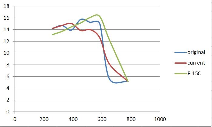
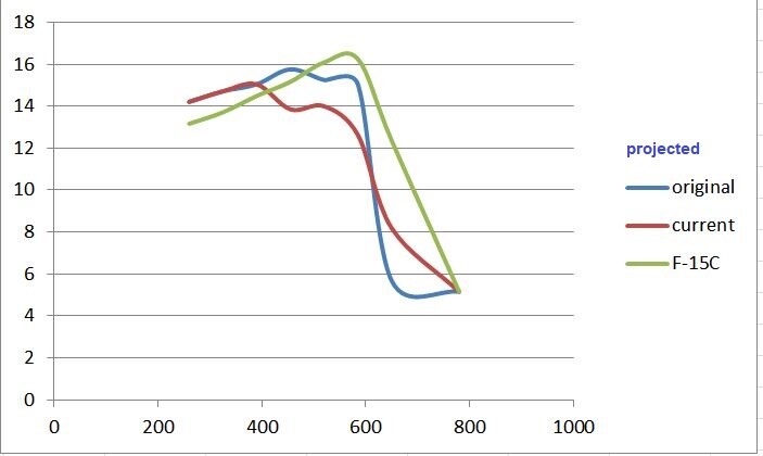
Results (STR, 5000ft, 4x4, half internal fuel) of data samples taken from the sim for the F-14A:
- first chart: current wing sweep program on auto and original wing sweep manually adjusted with the wing sweep lever
- second chart: same as the above, but mach 0.6 value projected to fallow the the same Cl/Cd values as the current wing sweep
- F-15C STR added for reference
It would seem the F-14's flew with both hands behind their backs, as except for the transonic envelope (literally around mach 1), the original wing sweep program would have given a much higher performance, up to 8g's sustained in the above mentioned configuration. Makes you wonder how things would have turned out had the Navy got all the jets they ever wanted...
EDIT: that mach 0.6 dip still sticks like sore thumb!
EDIT: say want you will about Maverick, but may just have had some idea about what he did when you pulled that emergency lever!

-
 1
1
-
-
-
33分钟前,tavarish palkovnik说:
@FWind you are THE KING of universe

If you would be near I would hug you so hard to extract life of you
I can’t see full document, it is locked for download, can you email me full text, it would be highly appreciated?
This is great, this is monumental!!!! Thanks mate a lot
-
1
-
-
17分钟前,tavarish palkovnik说:
Both those documents giving reference connection to Mk47 are good and helpful, however and after all, they only confirm that grain is with some kind of slots and that slots are with some kind of insulation. Of course, with general lack of any concrete data about geometry, even this is monumental.
But still, slotted grain configuration as general term is hugely wide. Can be slotted tube, kind of finocyl, can be slotted cylinder in full length, kind of keyhole form, with one or more slots etc etc.Momentarily data for Mk60 are the most concrete and detailed in description, 5000-1000 lbf, 20-30 sec, max. pressure 1000 psi, plus with known nozzle geometry what is very important. And no matter to all what can be read on internet, I believe Mk47 and Mk60 are very similar, in output numbers perhaps almost same because both had same task to fulfill, same requirements. Internally I don’t know, except that there is no much alternatives to get these numbers so perhaps even internally they are similar.
First guided flight in demonstration test of Phoenix missile was long time ago, it was May of 1966, so motors, in concept form, should be and looking for in that time of 60’s. It was time of lot of extravagant designs and I wouldn’t be surprised, when and if we finally get answer, to see something very strange for today’s norms.
This last variant I gave is such, not common for today, but Aerojet designed similar in 60’s, it was in use, and with accommodated number of slots it is easy to get numbers given to Mk60. It has slots, it has insulated slots and it gives output numbers easily.-
1
-
-
2023/9/26 PM6点09分,tavarish palkovnik说:
Since I can't add any attachment here, this is link to forum where I usually write and in last post is latest vision how Mk60 could looks like, if someone finds it interesting
Vanjskobalistički proračun (program) leta rakete (mycity-military.com)
-
-
16小时前,tavarish palkovnik说:
So like said, think that I managed to get to what is given for Mk60 Mod.0 motor and why not to share it here
I used this grain configuration, slotted tube, only with mutually dislocated slots to have this part with slots in participation all the time. Also I took and used data of slow burning USA propellant type RDS-501, common for that time and got this ->
It is very much on the trail of numbers given to Mk60 Mod.0, 20-30 seconds and average thrust values 5000-1000 lbf (22241-4448 N). Pressure is also on the trail, they said maximal is 1000 psi (69 bar) I got very close
This motor sucks down there at sea level as it supposes to do with nozzle like it is, however up there it gives what should give. If I would create this motor for purpose of this game, this is what I would do.
So I would make it as linear function from 23000 N to 4500 N of thrust during 25 seconds. It makes total impulse of 343750 Ns or average 13750 N or average specific impulse of 206,1 s. That is for sea level. To get numbers for altitudes, first with this motor principle of 7% should be forgotten because it sucks here. Actually any kind of single valued percentage for increasing should be avoided becuase it will give false result for this case. Here I would use instead of percentages increasing with adding extra force and for 10km it would be extra 3000 N in each second, all that can be explained of course.
Now it is from 26000 to 7500 N, total impulse of 418750 Ns and average Isp 251,1 s. And I would use function F f(t) instead of making it as continuous average thrust of 16750 N because these two inputs give sometimes very much different outputs.
Yes, total impulse is the same but...
This is some hypothetical ballistical shot from 10km at 1,5M with elevation of 20 deg where ''red'' is continuous 16750 N thrust.
And this is hypothetical horizontal flight at 10km with kinematic overload
In any case, function or continuous average thrust can go depending of desire for precision but with changing of thrust values with altitues, with this and similar motors, extra care should be taken
https://ntrs.nasa.gov/citations/19660024251

-
 3
3
-
-
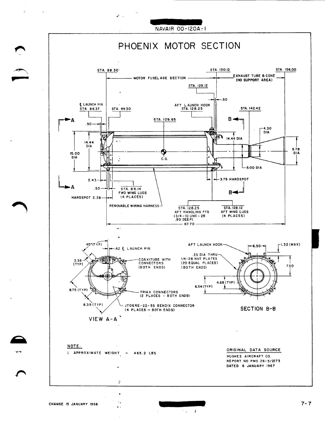
2022/12/4 AM12点25分,tavarish palkovnik说:
More or less but mostly
 everything can be calculated with just simple involving elementary study of rocket motors. Luckily there are plenty of motors sharing same diameter 380mm or 15’’ and having similar composite fuels so even visible differences forcing directions.
All these three are in 380mm
5V27 of S-125 Neva (SA-3), R-33 and Kh-58…all in same diameter as AIM-54
5V27 is primarily for low and near to intermediate altitudes and nozzle is sized respectively
Kh-58 is more for low intermediate and near to low altitudes
This motor’s cross section is my creation but I stand for it very firmlyAnd this is Mk47 Mod 0
with nozzle bell sized, obviously not optimized for sea level or intermediate altitudes but for up there altitudes just as R-33
http://aviationarchives.blogspot.com/2023/05/naval-air-launched-guided-missiles.html
-
2
-
-
-
-
-
-
-
-
29 minutes ago, DSplayer said:
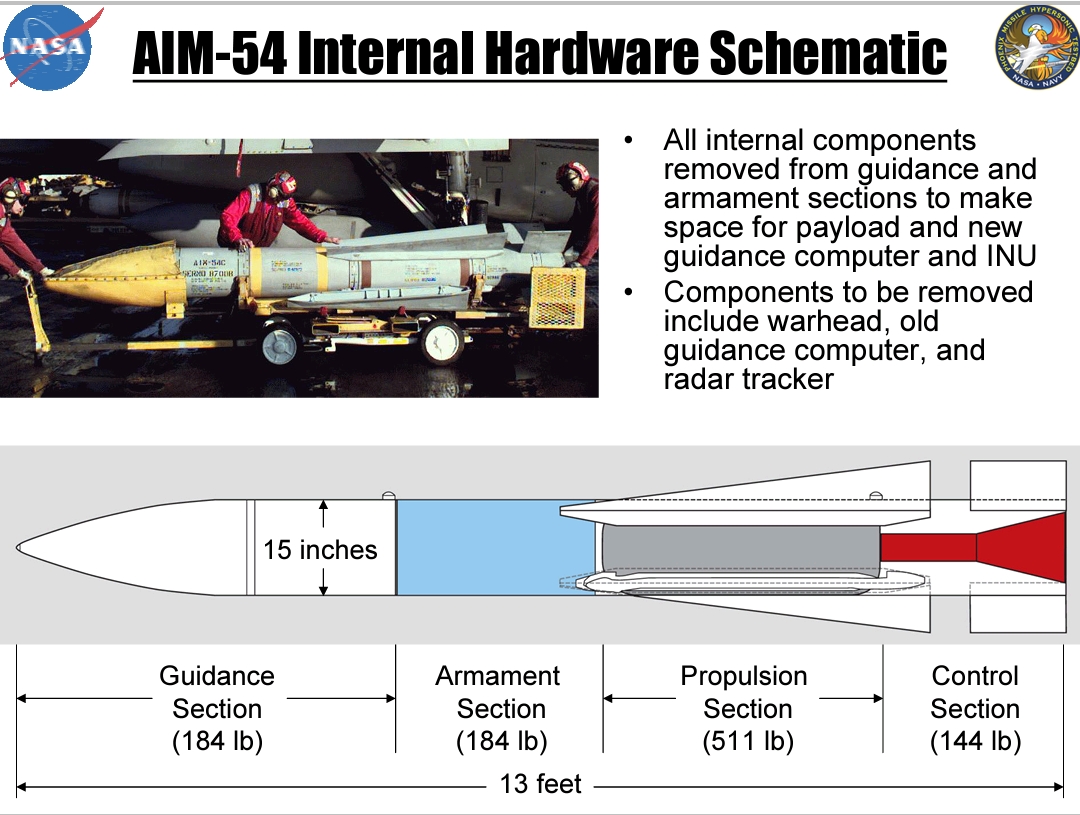
It's possible that the NASA Hypersonic Test Bed document/slideshow details the weight for the later model AIM-54C+ which perhaps has an even more improved motor over the Mk47 Mod 1? (Btw this document was also used in the old Whitepaper as a source)
https://www.globalsecurity.org/military/library/policy/navy/ntsp/aim54.htm
-
4 hours ago, Machalot said:
My opinion -- not representing HB or anybody but myself -- I think it's likely the Army document you're referring to is incorrect. I put together a comparison using the HB Aim-54 white paper. Numbers highlighted in red are what I consider suspicious and not likely realistic. The data in the AIM-54A-Mk60 column derives from the document in question. Note that the Mk60 somehow fits 45 kg (27.6%) more propellant into the same volume as the Mk47. In fact it appears to claim the Mk60 propellant mass is greater than the entire Mk47 rocket motor (including propellant, insulation, case, supporting structure, and nozzle). It's not really plausible. I think it's likely the 208 kg of propellant listed in that document erroneously included the entire Mk60 rocket motor, not just the propellant mass, and that the actual masses and performance of the two rocket motors is very close.
-
5 hours ago, cheezit said:
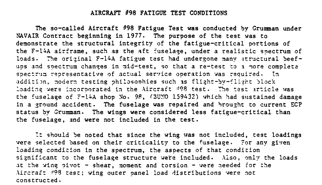
What was the deal with aircraft #98?
https://archive.org/details/DTIC_ADA193828/page/n15/mode/2up
-
1
-
-
-
-
-
-
2 hours ago, DSplayer said:
I guess there are former Tomcat pilots and maintainers that seemingly agree that there were flares and chaff that could be deployed from the BOL/LAU-138 rails for the F-14 (Jungle from Episode 9 and of course Tung from Episode 23 of the F-14 Tomcast) who can help support the implementation of flares for our F-14. Tung even had a great story that accompanied his episode where he described how the BOL-IR packages would create streaks along the horizontal stabs after using them.
It does make sense that a single BOL chaff module is roughly 1/4 as effective as a ALE-39 chaff cartridge since its roughly 1/4 the volume of one. But is it historical that a single press of the chaff deploy switch on the ALE-39 deploy 4 BOL modules in order to compensate for the lower chaff count or is it a thing you guys did to make the LAU-138 chaff bundles actually effective? If it is just a DCS thing, I wouldn't mind the ability for a special menu and a mission editor option for the disabling the LAU-138 firing 4 charges at once and bring up the LAU-138 chaff deploy count to 160 instead of 40 (since it would deploy 1 from each side instead of 4 from each side) even if its less effective than the typical DCS chaff charge.
Here's some documents I was able to find relating to the MJU-52/B flare cartridge for the LAU-138 but it's highly possible that you guys have already found these documents:
https://www.jmu.edu/cisr/research/OIG/Iraq/highres/09-Pyrotechnic.pdf
https://www.globalsecurity.org/military/library/policy/navy/ntsp/aecm-a_2001.pdf
- This one states that the MJU-52/B "which when expelled from the sealed container, performs similarly to the MJU-27A/B Decoy Flare [the flare cartridge used by the ALE-39] by generating heat through a pyrophoric process."
- "MJU-52/B utilizes the same flatpacks as the BOL chaff to facilitate operational use of the BOL dispenser. The difference between the RF and IR packages revolves around the different payload of the decoy devices"
It seems like there might be more information from "F-14A/B/D A/G TACTICAL MANUAL, NWP 3-22.5-F14A/B/D, VOLUME III, NAVAIR 01-F14AAD-1T-2" but I've been unable to find the document online.
Bol-IR in the video.
https://mega.nz/folder/WR9hwQoK#NXGsaNB-30aOO8Ki_KS0tA/folder/HY9VGTSa
-
-


.jpg.92d863bab4cfbd7d78311b24e4094d45.jpg)


DCS: F-14 Development Update - AIM-54 Phoenix Improvements & Overhaul - Guided Discussion
in DCS: F-14A & B
Posted