
OH1CL
-
Posts
31 -
Joined
-
Last visited
Content Type
Profiles
Forums
Events
Posts posted by OH1CL
-
-
I finished my first prototype F16 altimeter. I used an code i found here. Does anyone have a settings for the X27 stepper motor and the Easydriver controller. Resetting the meter works ok, but the readings do not match the program's meter
 .
.
-

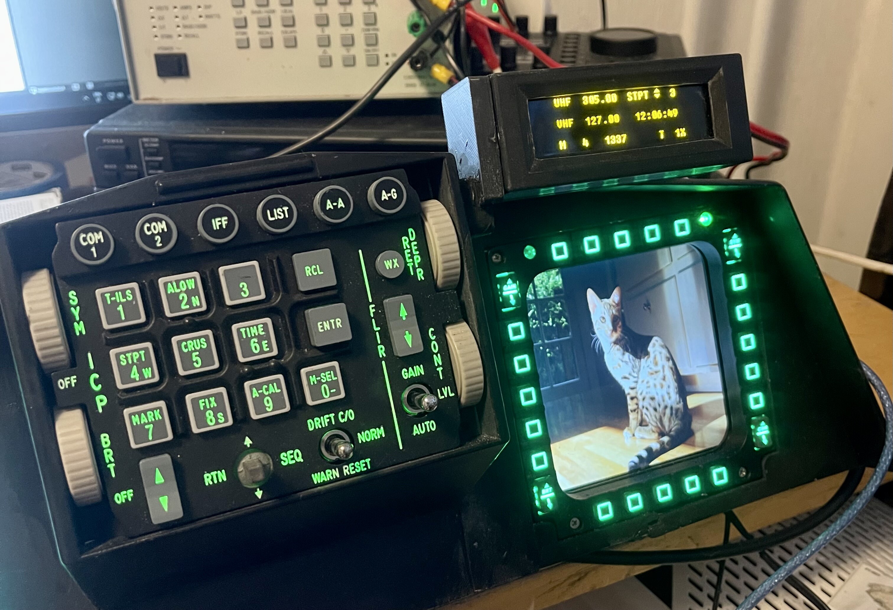
Here is a stl file for f16 iCP case. the photos is from first prototype version of the case. But attached file is the latest one. Please note that the picture shows the entire instrument panel for my multirole simulator
 The file is just an ICP case
You must add some supports for panel. This is my own design and only a "look a like version But the SIMGEARS ICP works with it very well.. icpcase.STL The dimensions are metric. As you can see from second picture, i have a case for DED too... Just ask if you want a stl file for it too..Here they are, both files for a ded case. You need 4 pieces brass support pillars for oled display too.dedcover.STLdedcasemain.STL
-
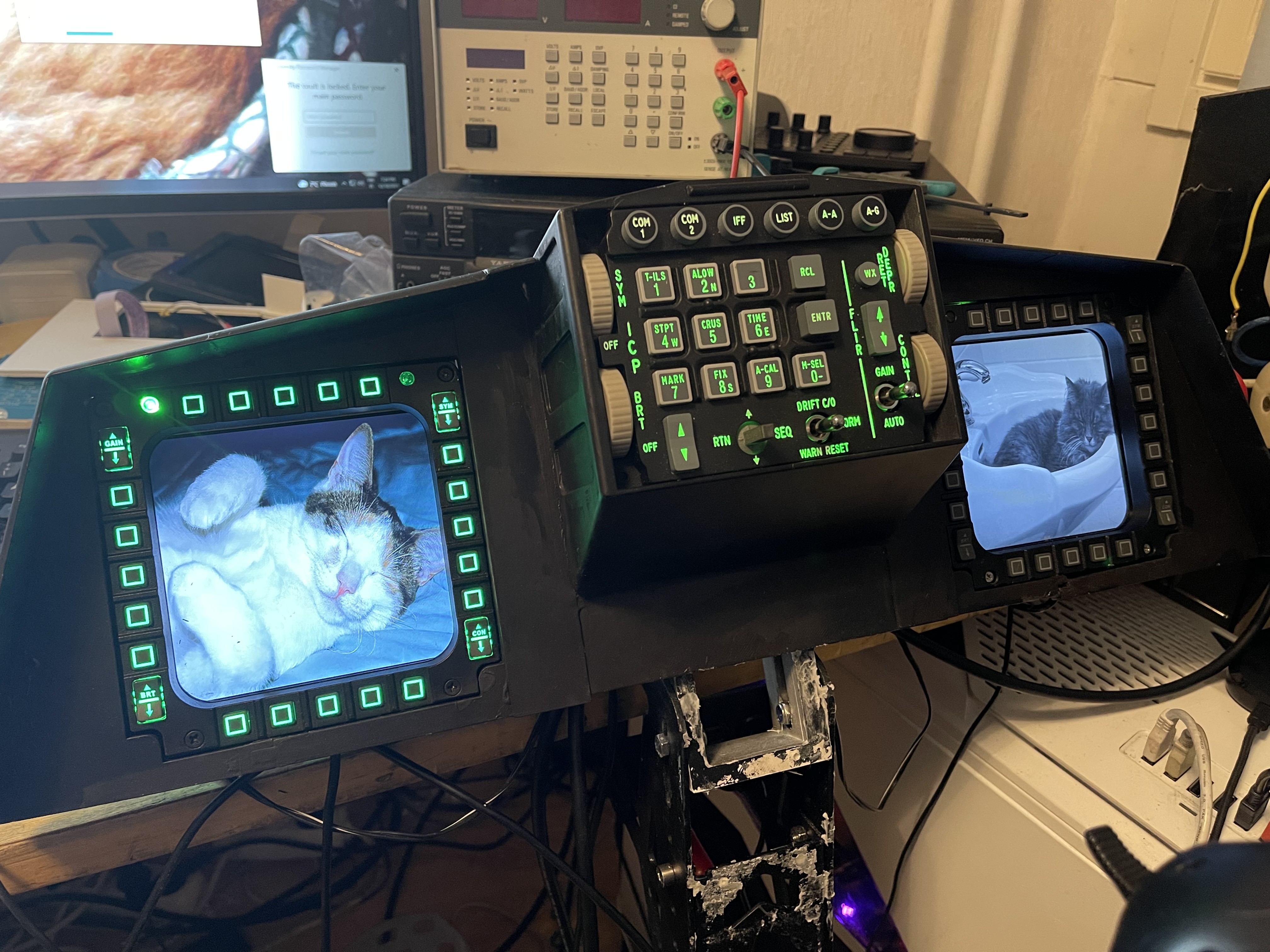
Now it is working… the case is 3Dprinted too.. looking very promising, indeed
-
42 minutes ago, fusion said:
Nice setup. Where did you get the ICP panel?
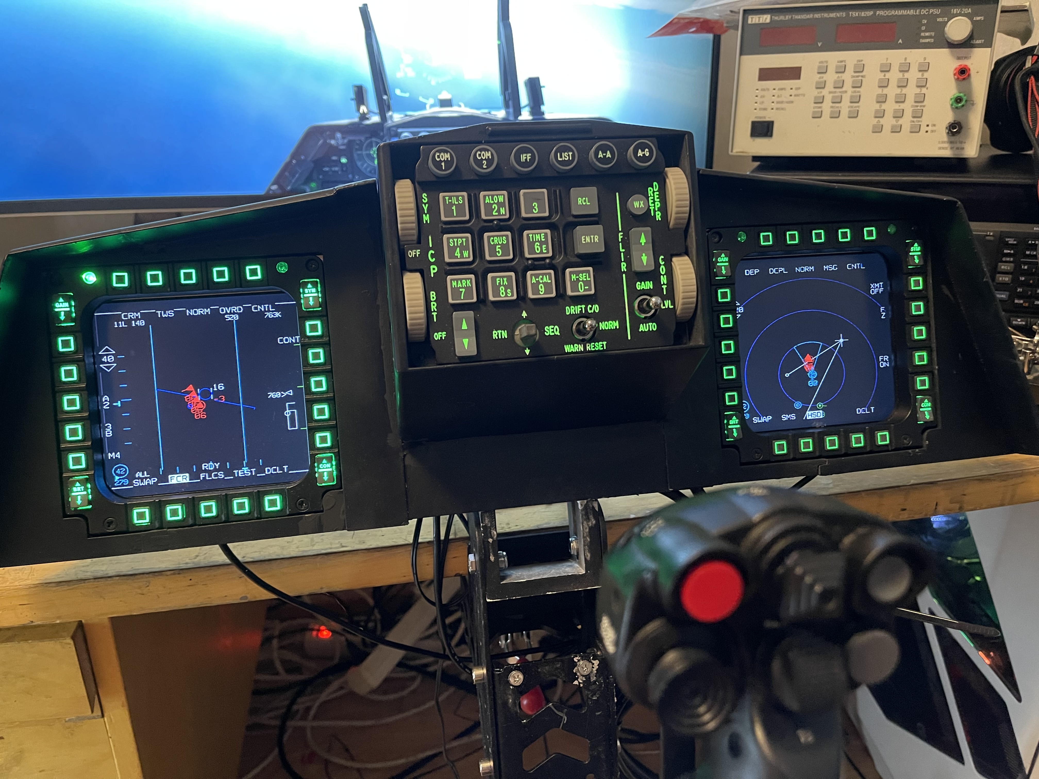
Thank you, this is my own design, 3D printed and it is still under the construction. I will add some needle instruments and buttons and switches from my favorite planes. This is a real multirole fighter panel, when i get it ready. Here is a link for ICP panel https://www.simgears.com/simgears-products/f16-icp-replica/
-
Thank you, i will try that when i am at home

-
It works, but some texts are missing from left side of the display ".UHF" & "VHF" and some others when there is a different paga on display.
-
Hi, after i bought and get my new Virpil stick and throttle installed, everything works like a dream. But at second day, my Virpil Ace pedals do not work any more. i check the usbcable, i change it to new one and then i plug it to other usb port. no function. then i check my Windows 10 device list, there are the stick and the throttle and and notice VPC device, driver error (10), Something about the device can´t started or something like that..remove the device . So what to do next
-
i am happy if somebody can help me with my problem. I can´t get any movement for my vid29 stepper + easydriver board. just want know how to connect those steppermotor wires (order) for the driver. I have some experiment with Helios and phidget´s but iam not familiar with Easydriver (clone) i did my test with code meant used with Arduino Max and multible steppers. DCSbios working, the led flashing during gaming in Arduino but nothing else than EasyDriver board is little hot. ;)
-
I tried a flapdemo again with the updated dcsbios and it's works! But did not testing it fully, Only the movement of the servo.
-
-
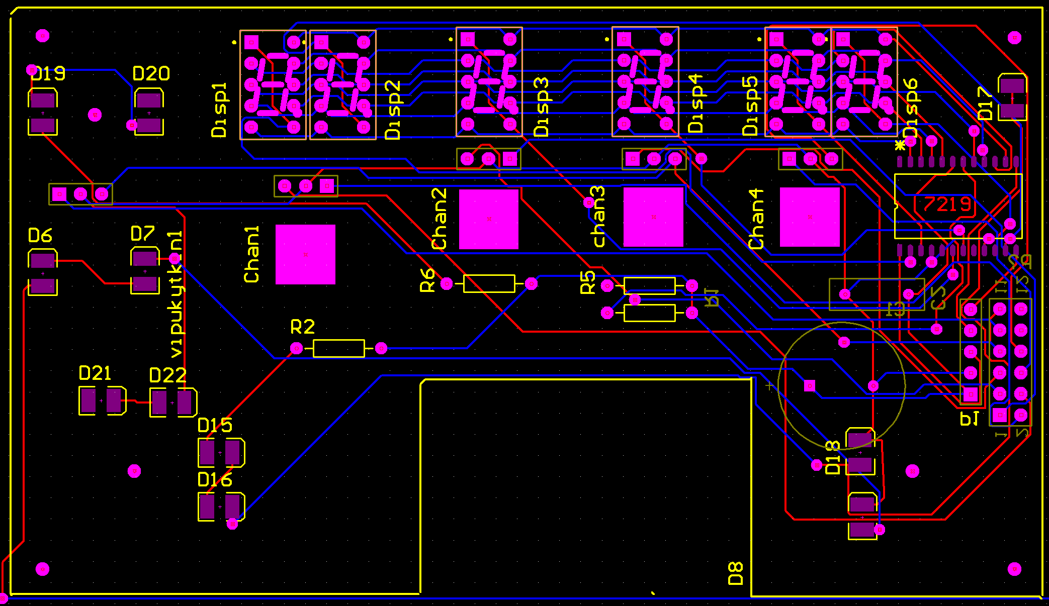
Here is a picture from my VHFAM radio pcb´s gerber file. It is still a prototype and testing state. My sketch did working, and when i get my laser engraver working i can make engraved panel for it and then i can do final tests with all swiches and rotaries are installed. i can order some pcb,s ;)
-
-
Here is updated 1:1 drawing from A10 cdu TOP panel Inside) based to my original cdu.
Some dimensions added.
-
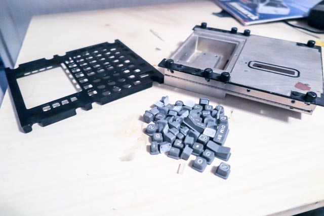
I bought some years ago original A10 CDU from EBay. Quite expensive piece of junk :)
Here is some part from it. I have them all somewhere :)
the top panel´s one corner is broken, and some buttons are missing. Original swiches are "foil" stype swiches like in cheap joysticks. And electronics(display etc.etc.) are useless too.
In a photo, there is my first attempt to build the top panel. but i am not satisfied for result,
now i have a new tft display for it and some Arduino Mega & Due boards. Maybe i get it at last to working condition. I must make a mold from those original switches and i have "clear" resin boughted. My new laser engraver do not work, maybe the tube is broken or the power supply. I order some spares. and during a waiting, i think i can start my CDU project again.
-
Hi, i upload a demo video from my clock sketch and my caution panel to Youtube.
here is a link:
if you can´t watch it, you must wait a little time.
They are not a full demonsrations, just a little hint about how they works. ;)
-
Hi, "40" watt SL-320 version, at first i think to buy bigger i have not a enough room for it in my work room. After it is arrived i have a plan to update it use to DSP controller too.
-
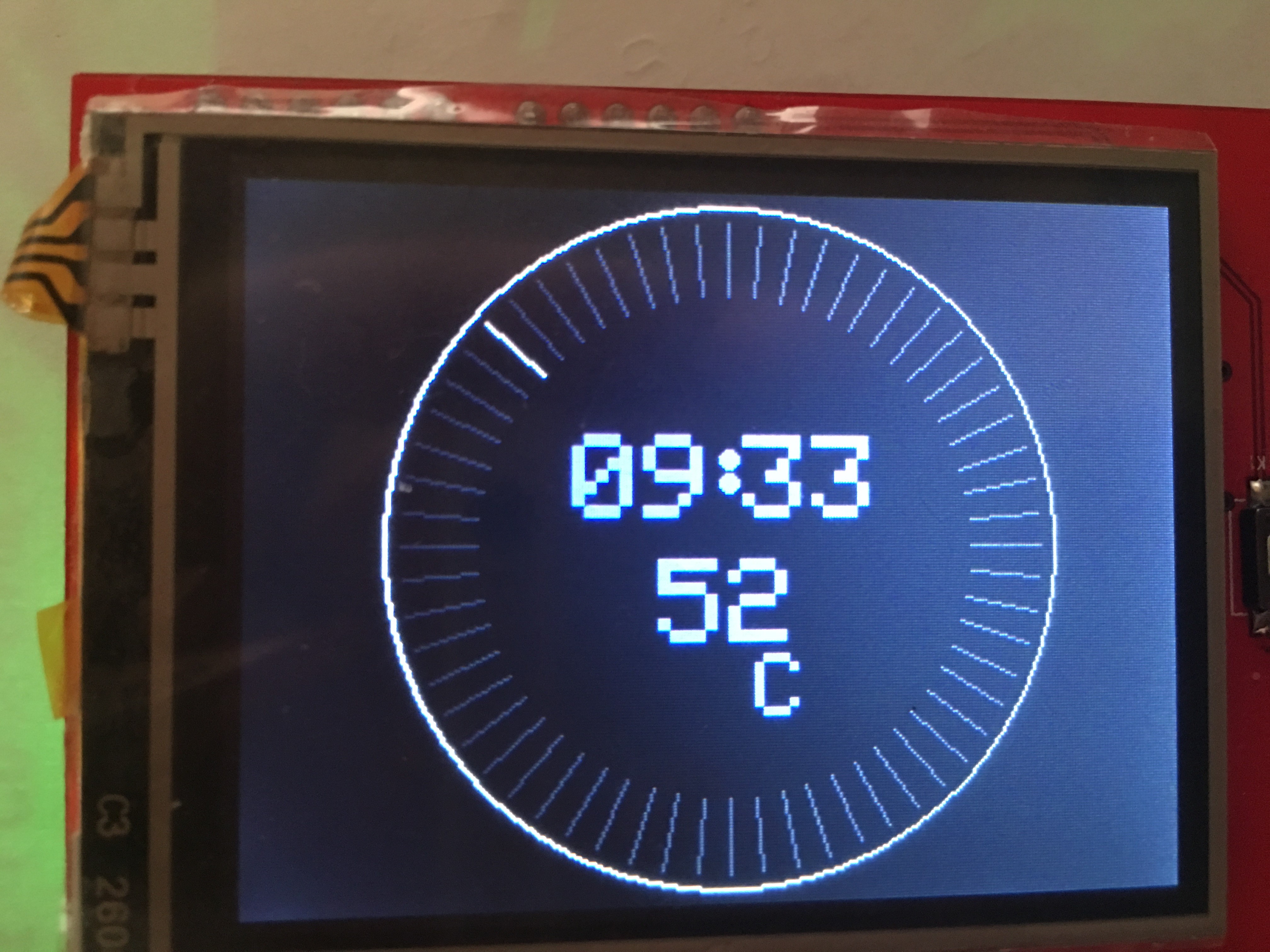
My sketch for A10 clock now working fully. I bought a display from EBay:
2.4" TFT LCD Shield SD Socket Touch Panel Module for Arduino UNO
At next week, i hope, my new laser engraver is arrived and then i get rest of my clock ready.
if somebody is interested about my sketch , send a private message. Then i can send all necessary files (free) with ae-Mail.. The TFT display needs its own library and modified Adafruit library too. I can send them all, with one .zip,packet.
-
 1
1
-
-
My problem is solved, Now i use a Default serial setting and now my skwtch works with Aeduino Due too.,
-
DCS-BIOS and Arduino Due
When i try upload my sketch to Due there was a problem with a serialpot registers. Sme sketch works fine with Mega. I Bought Due card bexause i have a plan use it with a EMI panel's stepper motors.so, what to do?
-
Aircraft instruments need those voltage :)
I think it can be very difficult to do it with Arduino.There is in EBay, aircraft inverters available.
-
Reason for modification
I bought from Ebay 7segment display module with 7219 controller attached.
and when i did a test with your code, it works but those numbers which are meant to be right was left etc.etc.
-
Hi, here is modifications what i did for your sketch, and now it´s works with my system.Btw at the original radio, i can´t see the decimal points trough those small openings...
/*
Tell DCS-BIOS to use a serial connection and use interrupt-driven
communication. The main program will be interrupted to prioritize
processing incoming data.
This should work on any Arduino that has an ATMega328 controller
(Uno, Pro Mini, many others).
*/
#define DCSBIOS_IRQ_SERIAL
#include <DcsBios.h>
#include <LedControl.h>
//pin 3 is connected to the DataIn
//pin 5 is connected to the CLK
//pin 4 is connected to LOAD
LedControl lc=LedControl(9,7,8,1); //This creates an instance of a single controller named "lc"
/*
The sequence of pins used above are in the following order... LedControl(DIN,CLK,LOAD,# OF IC's)
pin 3 is connected to the DataIn
pin 5 is connected to the CLK
pin 4 is connected to LOAD
the last number...(1) is for how many MAX7219 we have daisy chained.
*/
void onVhfamFreq1Change(char* newValue) {
lc.setChar(0,5,newValue[0],false);
lc.setChar(0,4,newValue[1],true);
}
DcsBios::StringBuffer<2> vhfamFreq1StrBuffer(0x1190, onVhfamFreq1Change);
void onVhfamFreq2Change(unsigned int newValue) {
lc.setChar(0,3,newValue,false);
}
DcsBios::IntegerBuffer vhfamFreq2Buffer(0x118e, 0x00f0, 4, onVhfamFreq2Change);
void onVhfamFreq3Change(unsigned int newValue) {
lc.setChar(0,2,newValue,false);
}
DcsBios::IntegerBuffer vhfamFreq3Buffer(0x118e, 0x0f00, 8, onVhfamFreq3Change);
void onVhfamFreq4Change(char* newValue) {
lc.setChar(0,1,newValue[0],false);
lc.setChar(0,0,newValue[1],false);
}
DcsBios::StringBuffer<2> vhfamFreq4StrBuffer(0x1192, onVhfamFreq4Change);
void setup() {
DcsBios::setup();
//This initializes the MAX7219 and gets it ready of use:
lc.shutdown(0,false); //turn on the display
lc.setIntensity(0,8);//set the brightness
lc.clearDisplay(0); //clear the display
//The following series of "lc.setChar" commands are used to display the number 8 in each digit. This allows us to see each that LED segment is actually working.
lc.setChar(0,5,'8',false);// The first number...0, means there are no other MAX7219's connected to the one we are using.
lc.setChar(0,4,'8',false);// The second number...1, indicates the digit you are sending data too...digit numbering starts at 0.
lc.setChar(0,3,'8',true);// The third number in single quotes is the character thats displayed
lc.setChar(0,2,'8',false);// The statement... true/false is to turn on or off the decimal point (dp) for that particular digit.
lc.setChar(0,1,'8',false);
lc.setChar(0,0,'8',false);
}
void loop() {
DcsBios::loop();
}
-
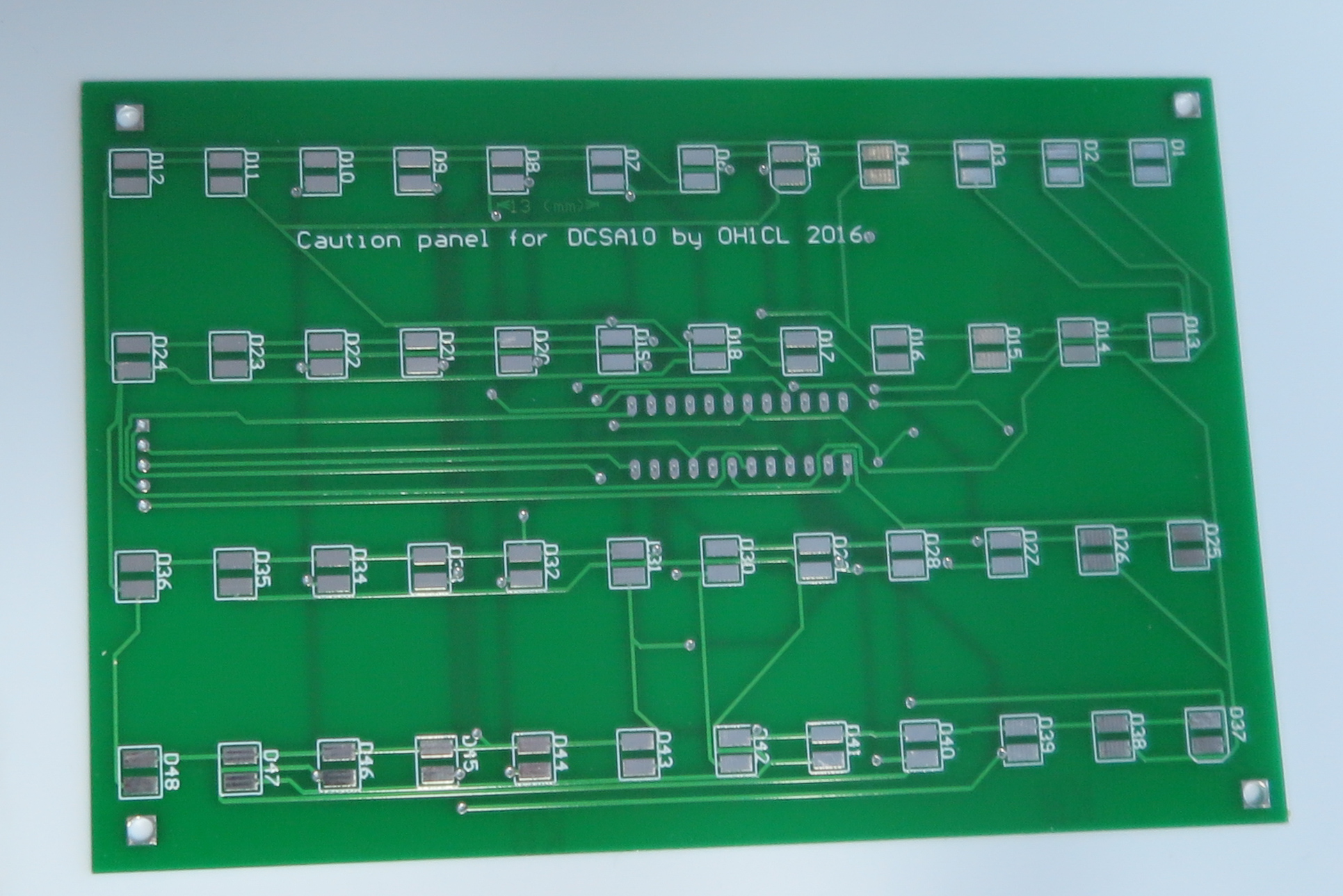
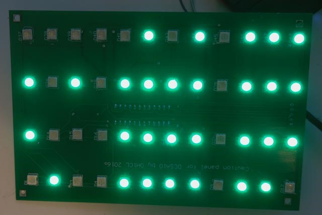
Thanks to Warthog and my friend, i have now a working caution lights panel. I have a 3 professional quality pcb´s left. it is dimensioned for 5050 leds and 7219 controller. I have some extra controller´s too. i have a working sketch for my board, it is little different than Warthog´s own. if you are interested, send a private message to me :)BTW. Here is photo from my panel, just after a battery power is switched on. Still 2 boards left :)
-
Hi, i am looking for A10 instrument face files. i have Cambam software, so dxf format can be suitable for engraving with it. i am happy, it somebody can send link to me, or those files. :smilewink:

F16 Arduino altimeter calibration...
in Home Cockpits
Posted
HI, thank you. I just ask that, because i think, maybe there is already a solution for my problem. And maybe my instrument, need some gears too,