
LJQCN101
-
Posts
509 -
Joined
-
Last visited
-
Days Won
1
Content Type
Profiles
Forums
Events
Posts posted by LJQCN101
-
-
I started to wonder if ED actually uses the roll command gradient curve from NASA FLCS (TP1538) and Analog FLCS, instead of DFLCS. So I did the maths.
In NASA FLCS and Analog FLCS, the roll gradient curve is pretty different from the one in DFLCS:
1. Analog FLCS requires 13.6 lbs stick force to command 179.2 deg/s, and 17 lbs to command 308 deg/s. Note that the maximum roll rate command is 308.
2. DFLCS requires 12.5 lbs to command 179.2 deg/s (as in the above test), and 17.57 lbs to command 324 deg/s. Note that the maximum roll rate command is 324.
(In case I'm drunk, the known figures in Analog FLCS roll command gradient curve are: 11 lbs for 80 deg/s, and linearly extends to 17 lbs for 308 deg/s. DFLCS: 9 lbs for 80 deg/s, and linearly extends to 17.57 lbs for 324 deg/s.)
So in Analog FLCS, it would require 13.6/17 = 80% stick input to command 179.2 deg/s, while in DFLCS the figure is only 71%.
And if you check the test result again, this exactly matches what currently is in DCS.
Smaller stick inputs may have had a bigger impact if Analog FLCS is used instead of DFLCS. For instance, at 11 lbs stick force, Analog FLCS is only able to command 80 deg/s roll rate, while with DFLCS the figure is 137 deg/s. That's a 71% increase.
-
 5
5
-
 1
1
-
-
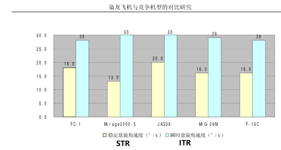
I know one document that matches his description of STR=18 and ITR=28:

The document is written by the school of Economics and Management, Beijing University of Aeronautics and Astronautics. It's publicly available (you can search for it's name), but the conditions are still no where to be seen. The aircraft in question is seems to be a prototype No.01-03.
PS: Appears to be the same guy: https://zhuanlan.zhihu.com/p/121523089
-
1
-
1
-
-
Okay I did a simple test to run through some figures according to the DFLCS block diagram.
Some preparations: (text in bold is for TL;DR)
1. I'm using active pause to stop the roll rate feedback from intervening the result, so that it's only about the stick input and the flaperon output.
2. I'm also choosing an high enough dynamic pressure (airspeed greater than 250 KCAS or Qc > 210 psf) and a low AOA (less than 4.2 degrees), and also elevator position less than 15 degrees TEU, to prevent the Roll Rate Command Limiter from reducing our maximum roll rate command. So the maximum roll rate command can stay at 324 deg/s.
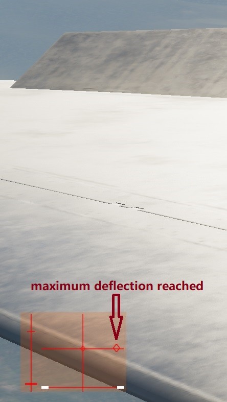
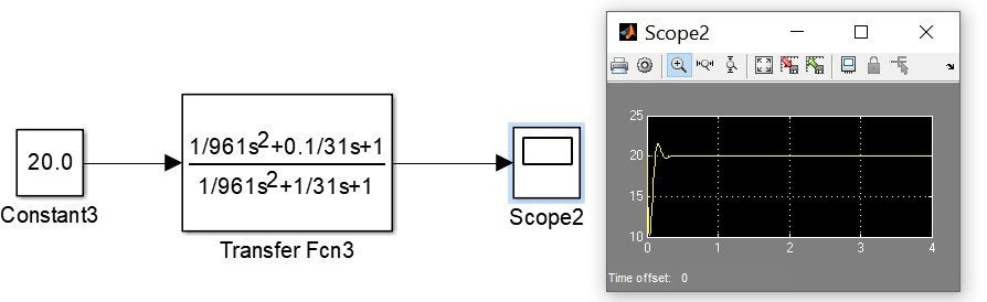
By freezing any other parameters, the lateral control law can be simplified as this: (roll rate command - roll rate feedback) * 0.12, apply a -21.5 to 21.5 limit, and then apply a 1.5 deg mechanical bias, so that the final output to flaperon ISA is 20 TEU to 23 TED.
So essentially, you're able to command a maximum flaperon deflection with a 21.5/0.12=179.2 deg/s roll rate command. By checking the DFLCS built-in roll command gradient curve, it corresponds to 12.5 lbs stick force, which is 71% of the full stick force range (17.57 lbs).
Now we're getting a reference point to perform a test, to see whether the flaperon reaches its full deflection at 71% stick input.
Test result:
So no, I'm using a stick input at around 80% to reach the maximum flaperon deflection. It means either the roll rate command value is a bit low or the 0.12 gain is questionable.
EDIT: rechecked the DFLCS curve, 179.2 deg/s actually corresponds to 12.5 lbs stick force, but the test result still stands.
-
8
-
1
-
-
13 hours ago, fapador said:
Yes the lag is very much sensible in FBW systems. However, note that it doesn't reduce the commanded roll rate or the sensitivity thus the control surfaces amount of deflection (in a way that DCS does) it just delays for some ms the command from happening. Its hard to describe if you have never had a go on a FBW plane.
The term reduce sensitivity is incorrect IMAO. It just makes the command happen at a later time (few ms).
I agree it may not be the best/correct term out there (if you consider the meaning in signal processing). A better term would be reduce input noise or jitter. Surely it does not reduce the maximum command with the transfer function. Roll rate command limiter is another block in the diagram.
The FCS of F18 doesn't have such designs. It has a 5 Hz notch filter applied to the stick lateral position sensor (Filter R2) but that's it. I'm yet to spot any lag filters in the path.
So the command can be sent to the aileron without any prominent delays.
On the other hand, I myself is a X65F user and I set 22 lbs for pitch and 13 lbs for roll, with the stick well fixed to the desk. Compared to T16000M that I also use as a backup, the time for me to reach the maximum force/stick deflection from neutral is a bit longer with a X65 than a T16000M, because of the much larger stick force. The end result is that I can feel more lag in the T16000M when flying the Viper because I can yank the stick so quick, the instantaneous lag between the filtered command and non-filtered command is very significant. But with the X65F, it's like you're moving the stick not as quickly, and the lag between the filtered command and non-filtered command is not so significant.
-
2
-
-
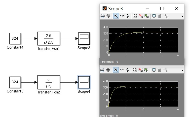
FYI apart from the built-in software breakout in the DFLCS, the roll rate command is also gone through a first order lag filter, which will induce lag and reduce sensitivity of the input.
The transfer function is 5/(s+5), which will change to 2.5/(s+2.5) depends on conditions (i.e. at higher dynamic pressures).
An example from SimuLink using a 324 deg/s roll rate command as input:
It would take around 1 sec to go from 0 to 324 with a transfer function of 5/(s+5).
-
4
-
1
-
-
TO answer OP's question it's a combination of an aero pack from the RL sim (simplified in the form of less LUT breakpoints), a CFD study of LERX+main wing (publicly available), RD93 tech doc, reverse engineering of CL&CD from EM diagram, and FCS tech doc including a set of control block diagram. Every sources complement each other. The equation of motion is a standard 6DOF rigid-body dynamics that is widely used in the industry.
-
2
-
6
-
-
5 hours ago, jianduankejiCN said:
OK this answers to your question. Click the image to zoom in.
Source: Chengfei (manufacture of JF-17)
combat weight: 7999kg
Sustained turn rate: 18deg/sec
Instantaneous turn rate: 28deg/sec
The only thing you could argue is the difference between block I and block II. However the changes in LEX shape only affect lift at high AOA, while the STR is achieved at low to medium AOA. There is no way the new LERX could increase the STR by 2deg/sec.In terms of the atmosphere condition, is there a severe difference between China's atmosphere and US atmosphere?
------------
Image deleted due to rule 1.16. However I believe lots of you have save it.
Now that we have a GW, but we still don't know the altitude and Engine Mode the flight test was based on.
Regarding atmosphere conditions, an increase in temperature of 10 degrees for example would reduce the turn rate by 1-2 deg/s, dependant on airspeed and altitude.
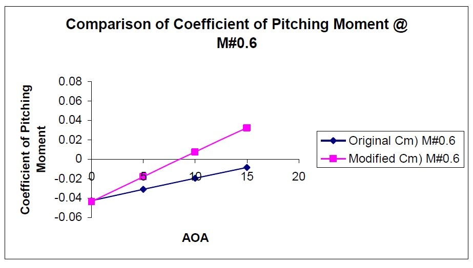
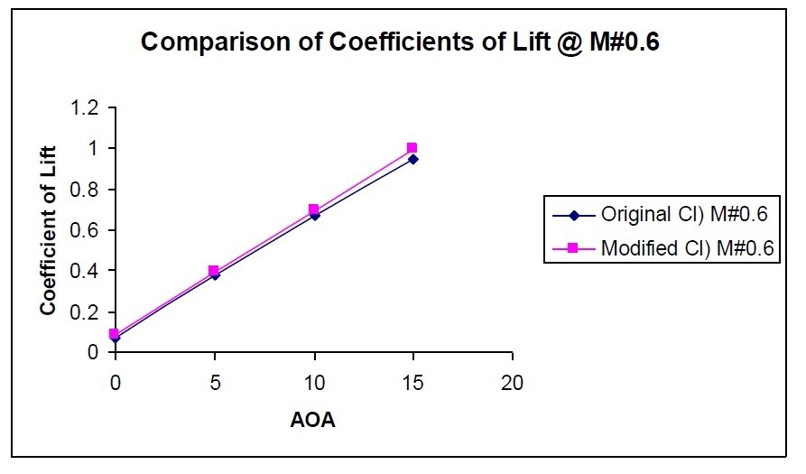
And for the LERX, the major difference was made since prototype No.04 and there's no difference between block I and block II. The effect is not only on lift coefficients (CL) but also on pitching moment coefficients (Cm), which greatly reduces trim drag in a maneuvering flight.
-
Now we're seeing some figures. In order for the fix to be efficiently pinpointed and pushed, please kindly provide the following conditions:
1. payload
2. Gross Weight or fuel weight
3. Thrust setting and Engine Mode (training, training-combat, combat)
4. deviation from the US Standard Atmosphere 1976
5. Altitude
6. Mach number at which the STR is obtained
If you're using airshow video materials, the following additional data is required:
7. Airspeed gain/loss
8. Altitude gain/loss
9. Evidence that the video is not edited
Then we can properly check them against our EM diagram, thanks.
-
1
-
-
If you think something's wrong, bring a track and the proof via private message or anything of your choice, and then the FM review process can continue. If you don't trust us, you can PM ED staff or community manager directly, i.e. Yo-Yo or Groove, .BIGNEWY or NineLine. I don't think anyone is suggesting that you should break the 1.16.
-
2
-
-
Follow up case opened, you're welcome to throw in anything.
-
Recently I come across this post:
I'll make a follow up case to see how I can utilize the proof, thanks.
-
3
-
-
Really, if the proof show that the JF-17 is overperforming, I'd love to make an adjustment more than anyone.
I'm just a coder anyways and the only thing I do is to stick to the graph etc.
-
2
-
-
Just saying, why would someone make a plane that overperforms in a game, is that any fun?
-
22 minutes ago, jianduankejiCN said:
As a person who collaborated with Deka Ironworks Simulation (DIS), I am pretty sure DIS over-performed JF-17 deliberately. China's official data (Chengfei) indicates the JF-17 a mediocre turn fighter with a STR of 18 deg/sec (I cannot post it here due to rule 1.16 but if ED contacts me I will show the proof). This number is in line with airshow demo if you use a stop watch to time its 360 turn, which is much longer than that of a Viper. DIS boosted it to 20+deg/sec. One of DIS employees told me that it is done deliberately by reducing trim drag and induced drag.
Also DIS exaggerated the performance of SD-10 to give it UFO-like maneuverability, and refuses to fix it. Enraged by its behavior, ED revoked some access of 3rd party devs and forces using official API for development.
If you think you have the proof, you can directly show to DIS. As far as I know we haven't collaborated with anyone.
Regarding trim drag and induced drag, we use official drag coefficients w.r.t alpha, beta, etc. and it's not any less than a Viper, no need to exaggerate anything. This sounds like more of a troll.
-
It's probably be reported as it was acknowledged by Bignewy:
-
33 minutes ago, TheBigTatanka said:
Yeah, a clean JF-17 flown by a competent pilot is a BFM monster. I don't think anyone (who can talk about it) has seen a JF-17 EM diagram, but in DCS it has better rate and radius ability than the new F-16 flight model. That doesn't make sense to me based on thrust to weight ratio alone (we should be able to beat it down on energy after a few lead turns, but we can't.)
Good news is that the Jeff doesn't have HOBS.... So shoot him early and often with a 9X.
Sent from my Pixel 3 XL using Tapatalk
The Jeff may have an edge at lower altitudes but you can beat it at heights, or use the vertical.
I don’t think the thrust profile of DCS JF-17 is in any way exaggerated, you can tell by its performance in the vertical.
The CL-alpha slope is roughly on par with the viper, while the CD0 is a little higher, being at around 0.025 with subsonic speeds. The wing area is slight smaller than that of the Viper. But if you sum it up all together, being a light weight fighter, it can still fly and fight at a lower AOA since less lift is required to compensate for the weight * Nz.
-
3
-
-
It's supposed to be fixed in this OB update.
-
On 2/26/2022 at 6:08 PM, Rmnsvn said:
I've spoken to an ex block 52 pilot from Polish air force and he told me that when you drop a bomb the aircraft slightly drops wing to the heavy side and corrects itself in a few moments.
I would use caution when dealing with pilot quotes, as we always cross-validate our SME's comments against other sources and other SMEs, and check if they're talking about the same version of the system.
But some fundamental designs cannot change easily, such as the g-command system of the pitch FLCS (cruise gains), and the P-controller in the roll FLCS. Those doesn't change from YF-16 to F-16 block 52 in any countries based on public engineering sources (i.e. control block diagrams) and dash ones. I doubt anyone can find an example that indicates otherwise. To make changes to those fundamental designs would require a complete validation of handling qualities in the entire envelope, which is not an easy or cheap task.
One famous example is an article by an USN test pilot, who wrongly suggests that the Viper's pitch FLCS is not a g-command system (in cruise gains). Mover dismissed his article as:
-
1
-
-
As per RD93 technical manual, there's an operational limit of 300 km/h IAS for the AB ignition. In DCS, it's directly related to the inlet pressure.
-
1
-
-
Hi, the lift effect is still there but the pitching moment seems off, fixed in next update. Not quite the same bug as F-18.
-
5
-
-
Look for 'Rudder Authority Limiter' in your dash 1.
In NASA TP-1538, an assessment was made to examine how the additional rudder might affect the departure-resistance characteristics of the configuration. The result shows that a large amount of proverse sideslip was detrimental for two reasons:
1. It acted through dihedral effect to augment the roll rate, which in turn coupled with the higher yaw rate caused by the larger rudder deflection to substantially increase the nose-up inertia-coupling moment.
2. It kinematically coupled with the high roll rate to cause an increase in angle of attack. The result was a rapid pitch-out departure despite the application of full nose-down stabilator by the control system.-
4
-
-
THX I'll check.
-
1
-
-
Hi, currently we're working on a new radar performance model, considering various factors affecting RCS and radar waves propagation.
We want to first implement three contributing factors: the variation of RCS with aspect angle (different model for different types of aircraft), the effect of atmosphere density and the effect of ground clutter.
Thanks.
-
23
-
2
-
-
4 hours ago, [PTF]Ali said:
@uboats Hi there, Thanks for the update. Would you guys mention what you have fixed so far. What really was the case here?
The fix is for the false detection of missile trails.
There is an anti-surge system in the JF-17, but is not fully implemented yet. Currently it will only detect a surge and counteract it by interrupting fuel flow for up to 3 sec. There's an anti-surge switch so that you can turn off the system.
When firing cannons or missiles, the system should activate.
The Mig-29 has a very much same system which I don't think is implemented in DCS. In addition to the anti-surge function that JF-17 has, the Mig-29 can also close it's intake ramp for an additional 10% maximum.


Roll axis Incredibly sluggish.
in Bugs and Problems
Posted
I think CAT III and Takeoff & landing gains are worth testing too. The DFLCS control logic are:
In CAT III, roll rate command is reduced by 134 deg/s, plus the reduction by the dynamic roll rate command limiter. So the maximum roll rate command is 324-134=190 deg/s.
In Takeoff & landing gains, CAT switch is ignored. The maximum roll rate command is 167 deg/s.