
Nikolas_A
-
Posts
119 -
Joined
-
Last visited
Content Type
Profiles
Forums
Events
Posts posted by Nikolas_A
-
-
It's a MS25212 panel, so width is 5.75".
If you find a good photo and scale it, you can calculate the length, rounding it up to a multiple of .375"
-
Are all 5 MFDs the same size on the Chinook?
-
Looking nice!
Two suggestions:
- Dome switches are better than tactile, more realistic activation forces, cheaper, longer lifer
- The knob is an overkill, print in clear, mask and paint. That's how the real ones are made
-
 1
1
-
On 1/6/2024 at 6:55 PM, No1sonuk said:
The bottom line(s)
Fusion 360 isn't really the best option for drawing complete gauge faces unless you intend to 3D print or engrave them. A vector drawing package like Inkscape (free) is better, and it can do all the line thickness and colour things you want.HOWEVER, F360 can help to make the gauge face fit your model by creating the template in F360, export as DXF, then finish it in Inkscape, etc. I do this with PCBs so they'll fit in the model.
That's my workflow too. I design the 3d assembly in NX, export the gauge face to dfx and import in Inkscape for lettering and scales.
I do miss the constraining capabilities of NX in Inkscape. I wish someone made a 2d CAD program with the capabilities that a parametric 3D CAD program has in the scetch environment...
-
2 hours ago, No1sonuk said:
If the wires are fixed at the ends, like wires usually are, they WILL twist as the gimbal turns. If it turns one way more than the others, the wires can't untwist.
That's what the slip rings are for
-
1
-
-
I used both, I forgot to mention hollow steppers!
-
1
-
-
On 11/19/2023 at 1:36 PM, BaronVonVaderham said:
Does anyone have plans/drawings/instructions for building an adi? I’ve seen plenty demos, but no one is sharing building information. I’m not sufficiently mechanically inclined to figure out the mechanical construction. Obviously they cannot turn infinitely around both axes. I cannot figure out the negatives of that soo I’m looking for examples/explanation on how to construct that.
Yes, they can. Google slip rings.
Here's my prototype:
(it doesn't turn infinitely in this clip but it can. That's just a demo Arduino sketch, swinging both axes back and forth a certain amount)
-
4
-
-
10 hours ago, Savvy said:
Perfect, thank you. I've just ordered 6 of them. If they are standard rotary switches I should be able to pull them apart to remove/cut out the plastic stopper tab which stops the continuous rotation.
May I ask why you would want to do that? At the F-16 at least there is no rotary switch with continuous rotation. Other a/c?
Or do you want to use it as an encoder?
-
On 4/30/2021 at 4:02 AM, jcagle said:
The font was made from scratch, using a pseudo telecentric image of the F/A-18 panel I posted above. Letters were cropped and calibrated based on size and then imported into a Font Builder where they were drawn/digitized one letter at a time (sample below). So I am not sure how directly the font features we've built will translate to the MS33558 font.
Also, as with all things hobby.....it's not finished yet! I have some sources for numbers, but would like them to be better.

That panel is not MS33558.
Matter of fact, MS33558 is mostly used on instruments, not panels. Most panels are Gorton Condensed, Futura Condensed etc
-
2
-
-
7 hours ago, lesthegrngo said:
youch on the price of the PC flights switch!
Thanks though, much appreciated - I'll have a look at the printed version
Les
For that price you can get a real, mil spec one:
-
2
-
-
1 hour ago, Vinc_Vega said:
Even with the proposed correction you definitely need a zero detection sensor for the HSI. Else your disk may drift after a while.
This is not necessarily so. The load on the stepper is light, not likely to loose steps. However, when you have optical zero reference, you can always use it in runtime to re-calibrate. If, e.g. you have an optical switch set to trip at 0°, everytime it trips you can check if your calculated position is indeed 0° or else update it
-
On 6/10/2023 at 8:26 PM, twistking said:
It might be ultraviolet fluorescence, where the material needs stimulation from a UV light source.
No such thing in the Viper, just incandescent lamps. They are either on or off
-
-
An A-7 HUD control panel, if anyone's interested:
-
The other one is a screw-on cap, probably pneumatic stuff under it.
-
Nice! I've programed a Micro to enumerate as four joysticks. Does anyone know if I can name them joystick1, joystick2 etc?
There's no worry about them being rearranged but it would be easier to assign functions to...
-
The first place to look for answers is the manual! The -1 says about the TRIM/AP DISC Switch:
DISC Deenergizes stick TRIM button, prevents autopilot engagement and ATF/autopilot blending, and deactivates trim motors (manual trim wheels still operative)
Plus, Lightning on Viperpits has opened up a real one. The photo links are dead but I have them saved somewhere.
The flight control system is the most vital in the a/c. There's nothing simple about it...
-
On 11/15/2022 at 1:28 PM, Dragon1-1 said:
Wheels in the real jet are not motorized, they don't move when the stick trimmer is actuated. This is why there are trim indicators next to them, to show the actual trim value, which is the combination of wheel and switch trim inputs.
They are motorized.
-
Gets my vote!
-
This is just the grip PCB. You have to connect it to the Cougar base or an alternative controller like an Arduino, see this project:
https://github.com/uriba107/fcc_controller/blob/master/src/Controller/Fcc3/fcc3.h
-
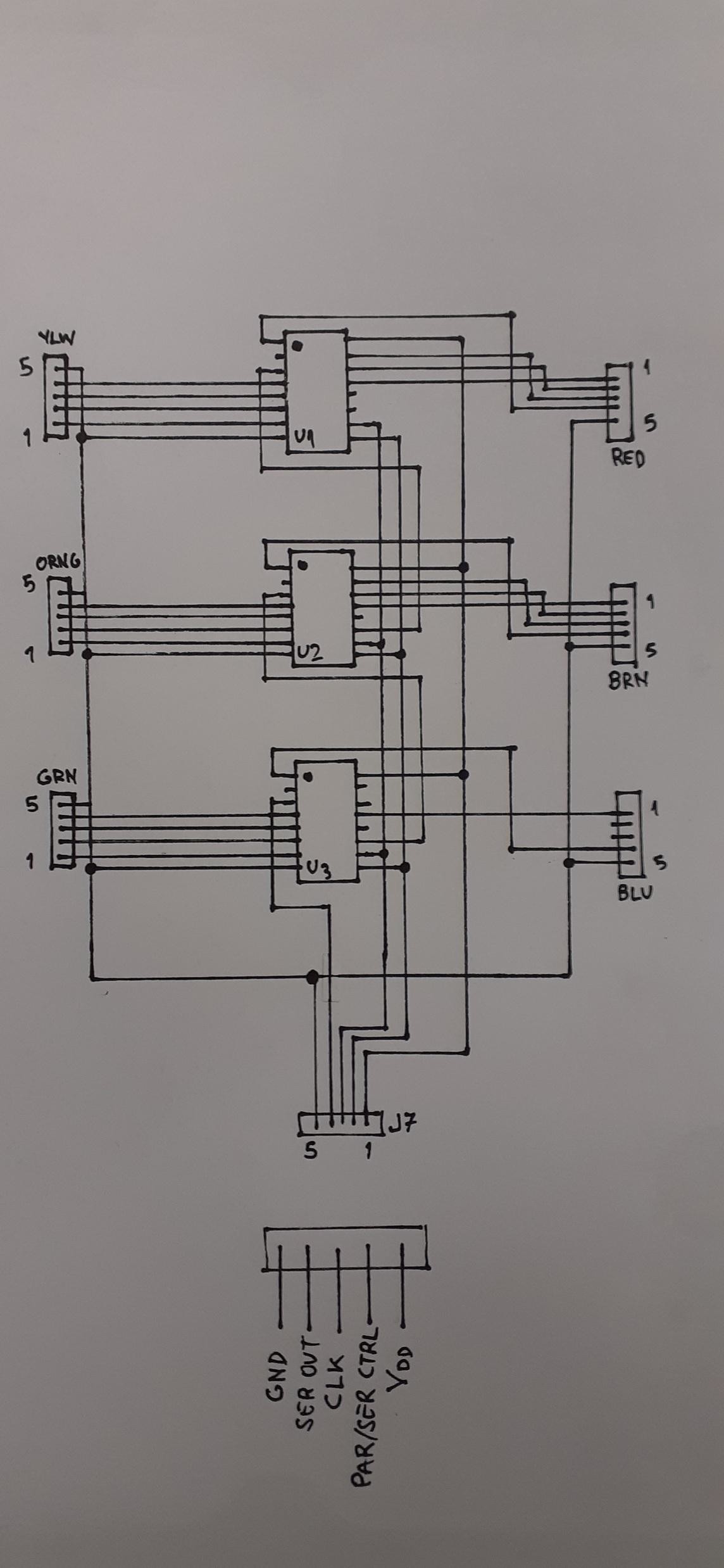
Hello, I have the schematic if you want to DIY it.
I can't find the board from one of my Cougars so I need one too. If there's interest, I could make the board layout and have them made (there's a 5 piece MOQ)
U1, U2, U3 : CD4021B
-
MPL3115A2 is I²C, not analog. Are you sure you have it wired correctly?
-
What's a platina?
-
I'm thinking an English wheel would be able to form the curves on the seat back but I haven't used one.

Does anyone have the panel dimensions for the CH-47 Pilot's CDU?
in Home Cockpits
Posted
Seems like 7.125" with a quick look