radonk1979
-
Posts
15 -
Joined
-
Last visited
Content Type
Profiles
Forums
Events
Everything posted by radonk1979
-

KA-50 PVI-800 - 1Bit 7 Segment Unit 5161AS
radonk1979 replied to radonk1979's topic in Home Cockpits
No that one was not working even with the corrected line. -
KA-50 PVI-800 - 1Bit 7 Segment Unit 5161AS
radonk1979 replied to radonk1979's topic in Home Cockpits
The above code works and is showing me the correct waypoint number on my 6bit display Cheers -
KA-50 PVI-800 - 1Bit 7 Segment Unit 5161AS
radonk1979 replied to radonk1979's topic in Home Cockpits
Thank you so much for your help and this code is working with the 6bit TM1637 module. I can see the display showing the correct information Next step is to convert this and figure out with the 1bit display is not working #define DCSBIOS_DEFAULT_SERIAL #include "DcsBios.h" #include <TM1637TinyDisplay6.h> //#define CLK 11 //#define DIO 12 TM1637TinyDisplay6 display(11, 12); // 6-Digit Display Class //Display bottom line airfield/fixed/target/correction point void onPviLine2PointChange(char* newValue) { /* your code here */ display.showString(newValue); } DcsBios::StringBuffer<1> pviLine2PointBuffer(0x1932, onPviLine2PointChange); //Display top line text void onPviLine1TextChange(char* newValue) { /* your code here */ //display.showString(newValue); } DcsBios::StringBuffer<6> pviLine1TextBuffer(0x1924, onPviLine1TextChange); void setup() { DcsBios::setup(); display.begin(); display.setBrightness(4); } void loop() { DcsBios::loop(); } -
KA-50 PVI-800 - 1Bit 7 Segment Unit 5161AS
radonk1979 replied to radonk1979's topic in Home Cockpits
I created a test code with the 6digit TM1637 display which I know is working. The top line text is working. I then mode the display line up to //Display bottom line airfield/fixed/target/correction point. When I do this the display is dark and is not showiing anything #define DCSBIOS_DEFAULT_SERIAL #include "DcsBios.h" #include <TM1637TinyDisplay6.h> //#define CLK 11 //#define DIO 12 TM1637TinyDisplay6 display(11, 12); // 6-Digit Display Class //Display bottom line airfield/fixed/target/correction point void onPviLine2PointChange(char* newValue) { /* your code here */ display.showString(newValue); } //Display top line text void onPviLine1TextChange(char* newValue) { /* your code here */ //display.showString(newValue); } DcsBios::StringBuffer<6> pviLine1TextBuffer(0x1924, onPviLine1TextChange); void setup() { DcsBios::setup(); display.begin(); display.setBrightness(4); display2.begin(); display2.setBrightness(4); } void loop() { DcsBios::loop(); } -
KA-50 PVI-800 - 1Bit 7 Segment Unit 5161AS
radonk1979 replied to radonk1979's topic in Home Cockpits
Updated code below. I tried the refreshDisplay in the Loop Part and were it is no. No success. Is there a way to find out what the value of newValue() actually is before trying to display it? #define DCSBIOS_DEFAULT_SERIAL #include "DcsBios.h" #include <SevSeg.h> SevSeg sevseg; //Display bottom line airfield/fixed/target/correction point void onPviLine2PointChange(char* newValue) { /* your code here */ //sevseg.setNumber(newValue); sevseg.setNumber(atoi(newValue)); sevseg.refreshDisplay(); } DcsBios::StringBuffer<1> pviLine2PointBuffer(0x1932, onPviLine2PointChange); void setup() { // put your setup code here, to run once: //Set to 1 for single-digit display byte numDigits = 1; //defines common pins while using multi-digit display. Left for single digit display byte digitPins[] = {}; //Defines Arduino pin connections in order: A, B, C, D, E, F, G, DP //byte segmentPins[] = {9,8, 7, 6, 5, 4, 3, 2}; //Braun, Rot, Orange, Gelb, Gruen, Blau, Lila, Grau byte segmentPins[] = {2, 3, 4, 5, 6, 8, 9, 13}; byte displayType = COMMON_CATHODE; //Use COMMON_ANODE for Common Anode display bool resistorsOnSegments = true; //‘false’ if resistors are connected to common pin //Initialize sevseg object. Use COMMON_ANODE instead of COMMON_CATHODE for CA display sevseg.begin(displayType, numDigits, digitPins, segmentPins, resistorsOnSegments); sevseg.setBrightness(50); //Seven Segment to show "0" at startup sevseg.setNumber(0); } void loop() { DcsBios::loop(); //Display numbers 0-9 with 1 seconds delay // for(int i = 0; i <= 10; i++) // { // if (i == 10) //{ //i = 0; //} // sevseg.setNumber(i); // sevseg.refreshDisplay(); // delay(1000); // } } -
KA-50 PVI-800 - 1Bit 7 Segment Unit 5161AS
radonk1979 replied to radonk1979's topic in Home Cockpits
Hi @Vinc_Vega I tired that and the display is staying blank. Below my code. Both version with the Int and converstion are not working and the display stays blank. At the bottom in the loop section is the sample where the display counts from 0 to 9. That is working so its means the cabeling and display is correct. Any other ideas>? #define DCSBIOS_DEFAULT_SERIAL #include "DcsBios.h" #include <SevSeg.h> SevSeg sevseg; //Display bottom line airfield/fixed/target/correction point void onPviLine2PointChange(char* newValue) { /* your code here */ //sevseg.setNumber(newValue); sevseg.setNumber(atoi(newValue)); } DcsBios::StringBuffer<1> pviLine2PointBuffer(0x1932, onPviLine2PointChange); void setup() { // put your setup code here, to run once: //Set to 1 for single-digit display byte numDigits = 1; //defines common pins while using multi-digit display. Left for single digit display byte digitPins[] = {}; //Defines Arduino pin connections in order: A, B, C, D, E, F, G, DP //byte segmentPins[] = {9,8, 7, 6, 5, 4, 3, 2}; //Braun, Rot, Orange, Gelb, Gruen, Blau, Lila, Grau byte segmentPins[] = {2, 3, 4, 5, 6, 8, 9, 13}; byte displayType = COMMON_CATHODE; //Use COMMON_ANODE for Common Anode display bool resistorsOnSegments = true; //‘false’ if resistors are connected to common pin //Initialize sevseg object. Use COMMON_ANODE instead of COMMON_CATHODE for CA display sevseg.begin(displayType, numDigits, digitPins, segmentPins, resistorsOnSegments); sevseg.setBrightness(50); } void loop() { DcsBios::loop(); //Display numbers 0-9 with 1 seconds delay // for(int i = 0; i <= 10; i++) // { // if (i == 10) //{ //i = 0; //} // sevseg.setNumber(i); // sevseg.refreshDisplay(); // delay(1000); // } } -
Hi Everyone, I am getting closer to finish my PVI-800 for the KA-50. The two 6bit 7 Segment Displays for LAT and LONG coordinates are working. Now I am working on the NAV Target display. DCS BIOS code: //Display bottom line airfield/fixed/target/correction point void onPviLine2PointChange(char* newValue) { /* your code here */ } DcsBios::StringBuffer<1> pviLine2PointBuffer(0x1932, onPviLine2PointChange); For that I am plannig to use a single 7 Segment display. I was able to get it to show numbers using the following libraries. sevseg.h -> used this example https://www.circuitbasics.com/arduino-7-segment-display-tutorial/ easysevenseg.h I was able to get both to work with the sample code for example a count down. But when I am trying to embed this in the DCS Code I am struggeling. I hope that someone can point me in the right direction. Am I useing the right libraries or am I better of trying to program everything manual like in this sample? https://circuitdigest.com/microcontroller-projects/7-segment-display-interfacing-with-arduino #define segA 2//connecting segment A to PIN2 #define segB 3// connecting segment B to PIN3 #define segC 4// connecting segment C to PIN4 #define segD 5// connecting segment D to PIN5 #define segE 6// connecting segment E to PIN6 #define segF 7// connecting segment F to PIN7 #define segG 8// connecting segment G to PIN8 int COUNT=0;//count integer for 0-9 increment void setup() { for (int i=2;i<9;i++) { pinMode(i, OUTPUT);// taking all pins from 2-8 as output } } void loop() { switch (COUNT) { case 0://when count value is zero show”0” on disp digitalWrite(segA, HIGH); digitalWrite(segB, HIGH); digitalWrite(segC, HIGH); digitalWrite(segD, HIGH); digitalWrite(segE, HIGH); digitalWrite(segF, HIGH); digitalWrite(segG, LOW); break; case 1:// when count value is 1 show”1” on disp digitalWrite(segA, LOW); digitalWrite(segB, HIGH); digitalWrite(segC, HIGH); digitalWrite(segD, LOW); digitalWrite(segE, LOW); digitalWrite(segF, LOW); digitalWrite(segG, LOW); break; case 2:// when count value is 2 show”2” on disp digitalWrite(segA, HIGH); digitalWrite(segB, HIGH); digitalWrite(segC, LOW); digitalWrite(segD, HIGH); digitalWrite(segE, HIGH); digitalWrite(segF, LOW); digitalWrite(segG, HIGH); break; case 3:// when count value is 3 show”3” on disp digitalWrite(segA, HIGH); digitalWrite(segB, HIGH); digitalWrite(segC, HIGH); digitalWrite(segD, HIGH); digitalWrite(segE, LOW); digitalWrite(segF, LOW); digitalWrite(segG, HIGH); break; case 4:// when count value is 4 show”4” on disp digitalWrite(segA, LOW); digitalWrite(segB, HIGH); digitalWrite(segC, HIGH); digitalWrite(segD, LOW); digitalWrite(segE, LOW); digitalWrite(segF, HIGH); digitalWrite(segG, HIGH); break; case 5:// when count value is 5 show”5” on disp digitalWrite(segA, HIGH); digitalWrite(segB, LOW); digitalWrite(segC, HIGH); digitalWrite(segD, HIGH); digitalWrite(segE, LOW); digitalWrite(segF, HIGH); digitalWrite(segG, HIGH); break; case 6:// when count value is 6 show”6” on disp digitalWrite(segA, HIGH); digitalWrite(segB, LOW); digitalWrite(segC, HIGH); digitalWrite(segD, HIGH); digitalWrite(segE, HIGH); digitalWrite(segF, HIGH); digitalWrite(segG, HIGH); break; case 7:// when count value is 7 show”7” on disp digitalWrite(segA, HIGH); digitalWrite(segB, HIGH); digitalWrite(segC, HIGH); digitalWrite(segD, LOW); digitalWrite(segE, LOW); digitalWrite(segF, LOW); digitalWrite(segG, LOW); break; case 8:// when count value is 8 show”8” on disp digitalWrite(segA, HIGH); digitalWrite(segB, HIGH); digitalWrite(segC, HIGH); digitalWrite(segD, HIGH); digitalWrite(segE, HIGH); digitalWrite(segF, HIGH); digitalWrite(segG, HIGH); break; case 9:// when count value is 9 show”9” on disp digitalWrite(segA, HIGH); digitalWrite(segB, HIGH); digitalWrite(segC, HIGH); digitalWrite(segD, HIGH); digitalWrite(segE, LOW); digitalWrite(segF, HIGH); digitalWrite(segG, HIGH); break; break; } if (COUNT<10) { COUNT++; delay(1000);///increment count integer for every second } if (COUNT==10) { COUNT=0;// if count integer value is equal to 10, reset it to zero. delay(1000); } }
-
I got it to work My code /* use '#define DCSBIOS_DEFAULT_SERIAL' instead if your Arduino board * does not feature an ATMega328 or ATMega2650 controller. */ #define DCSBIOS_DEFAULT_SERIAL #include "DcsBios.h" #include <TM1637TinyDisplay6.h> #define CLK 2 #define DIO 3 TM1637TinyDisplay6 display(CLK, DIO); // 6-Digit Display Class //Display top line text void onPviLine1TextChange(char* newValue) { /* your code here */ display.showString(newValue); } DcsBios::StringBuffer<6> pviLine1TextBuffer(0x1924, onPviLine1TextChange); void setup() { DcsBios::setup(); display.begin(); display.setBrightness(2); } void loop() { DcsBios::loop(); }
-
Hi everyone, Again thank you for your help with this post. I got everything to work as desired. When putting the display it looked a bit small to me as its using the 0.36inch modules. I was looking for the MAX7219 with 0.56inch but could not find anything. Instead I found these: https://www.aliexpress.com/item/1005001953449345.html?spm=a2g0o.order_list.order_list_main.11.245f1802ul3vC0 I am trying to get these to work using the different examples I could find onine. But not being a programmer is making this really challenging. I hope that someone could help me to get one as an example to work. Its not even showing anything My code: /* use '#define DCSBIOS_DEFAULT_SERIAL' instead if your Arduino board * does not feature an ATMega328 or ATMega2650 controller. */ #define DCSBIOS_DEFAULT_SERIAL #include "DcsBios.h" #include <TM1637TinyDisplay.h> #define CLK 2 #define DIO 3 TM1637TinyDisplay display(CLK, DIO); //set up the 4-Digit Display //Display top line text void onPviLine1TextChange(char* newValue) { /* your code here */ display.showNumber(newValue[5]); } DcsBios::StringBuffer<6> pviLine1TextBuffer(0x1924, onPviLine1TextChange); void setup() { DcsBios::setup(); display.setBrightness(7); } void loop() { DcsBios::loop(); }
-
DCS BIOS - PVI800 - 7 Segment 8Bit Display (MAX7219)
radonk1979 replied to radonk1979's topic in Home Cockpits
Thank you so much @Vinc_Vega I was able to get it to work. -
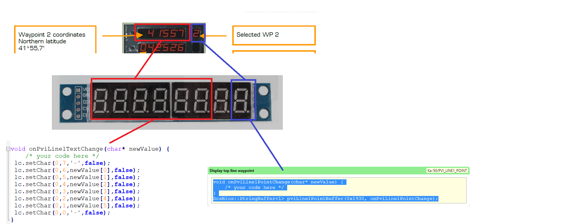
Hi everyone, I am currently using for the PVI 800 a 7 Segment 8Bit Display (MAX7219) to display the coordinate and the part in red works fine. What I know would like to do is to display the Selected WP2 on the last digit of the display. I am really struggeling to get this to work. How to use the display so that the first digits are being used for the cooridnates and the last one for the Selected Waypoint. I hope that someone can point me in the right direction

-
Hi everyone, I came acorss a few old forum posts regarding the cockpit dimensions for the KA-50. Unfortunatley the links in these posts with files to download are no longer working. Does anyone have these by any chance? Cheers
-
Hi everyone, I am new to DCS-BIOS and would need some help and advice with regards to my button box. In case this is the wrong forum please feel free to remove this post. The problem: I am designing a button box for a UH-1 with the aim to make it easier to fly in VR. Rather then always searching for the mouse or so I would like to have a box with to turn noobs or switches for example changing the radio frequency. All of this works. The problem I have for example is the overhead cabin light panel. There are (should) be 6 rotary switches to control the cabin and background light. I could use 6 rotary switches and map them 1 to 1 but as this is not intended to be a real replica of a cockpit and I am looking for something to make VR flighting easer I am looking for a more practical and cost effective solution. Is there a way to have 1 switch or button execute multiple commands? In this case I rotate 1 rotary switch and in DCS all 6 are rotating? Limitations: Unfortunately I am not a software developer so my ability to read and write code is limited Any help is appreciated.
-
Hi Bss_Sniper, its quite interesting that you say other players seam to not have these problems. Would you be available for a quick trial one of these days?
-
Hi everybody, are there any other Middle East based DCS players out there? From some reason the servers I tried in the US and Europe have so much lag that we warp around more then actually able to fly together. I am trying gather a few people to fly together on a more or less regular base. Interested? Let me know Cheers Kasten