Regnad517
-
Posts
48 -
Joined
-
Last visited
Content Type
Profiles
Forums
Events
Everything posted by Regnad517
-
So wait, can the Mega not be used as an actual DCS-Bios board while acting as the Master? If I remove the serial define it fails to compile unfortunately
-
So I got the chips in this week and have given it the old college try. I cannot get the slave to communicate with the master and I feel it's one of 2 things. Either I have my RX/TX wrong since I am using an Uno rather than a Nano, I assumed it would still be rx/tx. Or my code is missing something. Master Code #include <Wire.h> #include "SevenSegmentTM1637.h" #define TM1637_MAX_LINES 1 // number of display lines #define TM1637_MAX_COLOM 4 // number of coloms (digits) SevenSegmentTM1637 am(2,3); #define DCSBIOS_DEFAULT_SERIAL #include "DcsBios.h" #define DCSBIOS_RS485_MASTER #define UART1_TXENABLE_PIN 7 //Yes I am using Pin 7 void onVhfamFreq1Change(char* newValue) { am.setCursor(0,0); am.print(newValue); } DcsBios::StringBuffer<2> vhfamFreq1StrBuffer(0x1190, onVhfamFreq1Change); void onVhfamFreq2Change(unsigned int newValue) { am.setCursor(0,3); am.print(newValue); } DcsBios::IntegerBuffer vhfamFreq2Buffer(0x118e, 0x00f0, 4, onVhfamFreq2Change); void setup() { DcsBios::setup(); am.init(); am.clear(); } void loop() { DcsBios::loop(); } Slave Code #define DCSBIOS_IRQ_SERIAL #include "DcsBios.h" #include <Wire.h> #include <LCD.h> #include <LiquidCrystal_I2C.h> #define I2C_ADDR 0x27 // I2c Address #define DCSBIOS_RS485_SLAVE 11 #define TXENABLE_PIN 2 LiquidCrystal_I2C lcd(I2C_ADDR,2,1,0,4,5,6,7); /* paste code snippets from the reference documentation here */ void onTacanChannelChange(char* newValue) { lcd.setCursor(0,0); lcd.print(newValue); } DcsBios::StringBuffer<4> tacanChannelBuffer(0x1162, onTacanChannelChange); void setup() { // Define LCD lcd.begin (16,2); // 16x2 LCD // Switch on the backlight lcd.setBacklightPin(3,POSITIVE); lcd.setBacklight(HIGH); DcsBios::setup(); } void loop() { DcsBios::loop(); } Each board works great independently but cannot get communication with the slave when chained. I'm pretty sure wiring is correct, have gone over it many many times. Everything powers up, just no communication. Thanks I have found that it sinks in better with sample code, if anyone can help I'd be thankful
-
Thank you so much for the sample code Ganeshka, I see what I was doing wrong simply from that! I can't wait to actually start putting this all together and posting some pics!
-
Yup, me again. Believe it or not I have done quite a bit on my own without asking for help. Anyway, here is my current issue. Working with TM1637 7 segment display. Using Digital clock from a10c as my test but keep getting an error. Here is an example of quick test code that works as far as general display #include <TM1637Display.h> const int CLK = 2; //Set the CLK pin connection to the display const int DIO = 3; //Set the DIO pin connection to the display int numDisplay = 60; //Variable to interate TM1637Display display(CLK, DIO); //set up the 4-Digit Display. void setup() { display.setBrightness(0x0a); //set the diplay to maximum brightness display.showNumberDec(numDisplay); //Display the Variable value; } void loop() { } Now I tried to modify it a bit for use in DCS-Bios like this #include <TM1637Display.h> #define DCSBIOS_IRQ_SERIAL #include "DcsBios.h" const int CLK = 2; //Set the CLK pin connection to the display const int DIO = 3; //Set the DIO pin connection to the display TM1637Display display(CLK, DIO); //set up the 4-Digit Display. void onClockHhChange(char* newValue) { display.showNumberDec(newValue); } DcsBios::StringBuffer<2> clockHhBuffer(0x10fe, onClockHhChange); void setup() { DcsBios::setup(); display.setBrightness(0x0a); //set the diplay to maximum brightness } void loop() { DcsBios::loop(); } I am getting an invalid argument from int to char when it tries to compile. I will be the first to admit I might be getting in over my head a bit with this one but have read many times, if arduino can control it, so can dcs bios. Any help out there? Thanks
-
Great, thanks for the replies. Will check your setup out soon quick.
-
Awesome. I’m planning very similar. Separated my cockpit into sections like you did. Currently I’m on 9 touch screens but am completely rebuilding from scratch to do away with the touchscreens. I too don’t see why an i2c lcd wouldn’t work. Only asked to see if you had tried it. Don’t spend too much time on it, I can test that when my chips arrive. Cheers
-
Yup, me being anxious. Thanks Warhog So looks like China is only option I can find online but curious, there are low powered and high powered ones (cpa, csa, eepa). I’m assuming since we are looking for only 5v that the low power cpa are adequate? Thanks
-
That is a huge help. Wish I'd found it earlier. Want to make sure I am understanding properly if you don't mind. 1) so you need a 485 for each arduino board. 2) you then just wire up the arduino normally per switch, buttons, etc... 3) can you still utilize i2c components with this such as lcd? 4) your schematic you left was a huge eye opener. If I'm reading that properly, those 4 arduinos will now work over 1 com port? Either way, I'm ordering a 10pack of 485s right now to start playing. Hope I don't become a pest. Lol. I do try to figure it out myself and come here with questions when I am spent. Thanks a bunch Han.
-
So I have read about 50 pages of threads here and am left with some questions. Though I don't consider myself an"electrical" person, I have done pretty good so far (with a question here and there and so terrific help from this site and its users). So I've decided I want to basically run each panel from an independent arduino, so tacan will have its own, caution, radios, cdu, etc... And I have figured out how to actually get that running with the multiple cmd script and such. My question is..there has to be a better way to do this than having 20-30 usb cords running to a hub. What happens if I plug a thumb drive in, do the com ports get reassigned, etc... I think my answer has something to do with either an RS-485 bus or an i2c bus. My problem is I really don't know what those are or how to implement them. And will they actually remove the need for 20 usb cords, 20 com assignments, etc... Any insight or pointing in a direction to find out more about this would be very much appreciated. I've dove in head first, CNC machine, engraver, even cncing my own circuit boards from copper so I really want to grasp this idea. Can't wait to start a "Regnads cockpit" thread with some of the things I have in the process. Thanks again. This is a great community. :pilotfly:
-
Yup that was it, moved 0 and 1 to 8 and 9 and all is well. Thanks so much
-
Im curious if there is something to alter since the LCD tutorial because I cannot get my LCD to display from DCS. I dont't believe it is a wiring or potentionmeter issue because if I load a simple "hello world" it displays fine. Here is a quick test I have been using simply trying to get a return value. /* Tell DCS-BIOS to use a serial connection and use interrupt-driven communication. The main program will be interrupted to prioritize processing incoming data. This should work on any Arduino that has an ATMega328 controller (Uno, Pro Mini, many others). */ #define DCSBIOS_IRQ_SERIAL #include "DcsBios.h" #include <LiquidCrystal.h> LiquidCrystal lcd(0, 1, 4, 5, 6, 7); /* paste code snippets from the reference documentation here */ void onClockHhChange(char* newValue) { lcd.setCursor(4,0); lcd.print(newValue); } DcsBios::StringBuffer<2> clockHhBuffer(0x10fe, onClockHhChange); void setup() { lcd.begin(16,2); lcd.clear(); DcsBios::setup(); } void loop() { DcsBios::loop(); } In my opinion, that should display the Hour from the clock yet my screen is just blank, illuminated but blank. And as I said, if I load Hello World it displays just fine and yes I am using 0,1,4,5,6,7. Thanks
-
Yeah works great. I even now have the multiple cmd script running working 2 panels currently. Thanks again. I’m sure this isn’t the last question I will have for this is all new to me but fascinated me.
-
well now Im wondering if I am an idiot and was supposed to edit that line for the com port? this is the text from the original @echo off REM Specify the COM port number to connect to in the following line. REM If set to the default value of ASK, the script will ask you to type it in each time. set COMPORT=6 REM Set PROTOCOL to "TCP" if UDP does not work for you. When using TCP, REM you have to start the script after you have started the mission and the simulation REM has been unpaused, otherwise the connection will fail ("Connection refused"). set PROTOCOL=UDP set VERBOSE=-v set MODE_OUTPUT_REDIR=CON if "%1" == "/Q" ( set VERBOSE= set MODE_OUTPUT_REDIR=NUL shift ) if not "%1" == "" set COMPORT=%1 if "%COMPORT%" == "ASK" set /p COMPORT=Enter a COM Port Number: set /A TTYNUM=%COMPORT%-1 if "%MODE_OUTPUT_REDIR%" == "NUL" echo Connecting to COM port %COMPORT% mode COM%COMPORT% BAUD=250000 PARITY=N DATA=8 STOP=1 TO=off DTR=off > %MODE_OUTPUT_REDIR% timeout 2 if "%PROTOCOL%" == "UDP" socat\socat %VERBOSE% UDP4-RECV:5010,ip-add-membership=239.255.50.10:0.0.0.0,reuseaddr!!udp-sendto:localhost:7778 /dev/ttyS%TTYNUM% if "%PROTOCOL%" == "TCP" socat\socat %VERBOSE% TCP4-CONNECT:127.0.0.1:7778 /dev/ttyS%TTYNUM% pause Doesnt work with that BUT works with this @echo off REM Specify the COM port number to connect to in the following line. REM If set to the default value of ASK, the script will ask you to type it in each time. set COMPORT=6 mode COM6 BAUD=250000 PARITY=N DATA=8 STOP=1 TO=off DTR=off REM Set PROTOCOL to "TCP" if UDP does not work for you. When using TCP, REM you have to start the script after you have started the mission and the simulation REM has been unpaused, otherwise the connection will fail ("Connection refused"). set PROTOCOL=UDP set VERBOSE=-v set MODE_OUTPUT_REDIR=CON if "%1" == "/Q" ( set VERBOSE= set MODE_OUTPUT_REDIR=NUL shift ) if not "%1" == "" set COMPORT=%1 if "%COMPORT%" == "ASK" set /p COMPORT=Enter a COM Port Number: set /A TTYNUM=%COMPORT%-1 if "%MODE_OUTPUT_REDIR%" == "NUL" echo Connecting to COM port %COMPORT% mode COM%COMPORT% BAUD=250000 PARITY=N DATA=8 STOP=1 TO=off DTR=off > %MODE_OUTPUT_REDIR% timeout 2 if "%PROTOCOL%" == "UDP" socat\socat %VERBOSE% UDP4-RECV:5010,ip-add-membership=239.255.50.10:0.0.0.0,reuseaddr!!udp-sendto:localhost:7778 /dev/ttyS%TTYNUM% if "%PROTOCOL%" == "TCP" socat\socat %VERBOSE% TCP4-CONNECT:127.0.0.1:7778 /dev/ttyS%TTYNUM% pause Note the addition of the line at top after SET
-
OK - So running the mode command made it work but after a reboot it wouldn't work again so I added it to the .cmd file and now all is great Thanks Ian
-
Well I guess I spoke a little too soon but I did find out EXACTLY what to ask this time. Might make a new thread in case this one gets overlooked thinking it is resolved. So here is what is happenning. If I boot up, run the cmd file - doesn't work BUT If I open arduino, run the serial monitor, set baud to 250000 and test, then run cmd, works great. So what can I alter to let it run without having to monitor the serial every time? Thanks
-
Well now I don't know if I'm upset or relieved. I tried running cmd after dcs started and unpaused but no luck, that only needs to be down when using TCP I'm pretty sure. I did notice all of a sudden that cmd was laggy. So I reuploaded to the arduino double checking all of my settings, then ran again starting cmd before DCS and it works perfectly. I'm one of those people that wants to know how I fixed it, and here I have no clue but guess I will run with it. Thanks for all the help to anyone that viewed this thread. Keep doing what you're doing, great stuff!!
-
Actually no, I was under the impression that only needed to be done when running tcp rather than Udp. Will try that soon
-
Here they are. Setting up Windows 10 on another machine as well just as a test to try and see if it happens there too

-
Interesting, I get backwards question marks Is that a baud issue and if so how do I rectify. All the settings I can find are at 9600 I did have a hell of a time getting a driver for the Uno on Windows 10 Edit: So when I change the baud in serial monitor to 250000 i get the proper output, not sure how to modify it on system though?
-
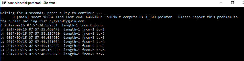
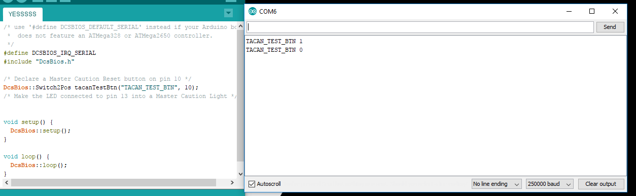
Yeah its frustrating me badly. No 3rd party firewalls or virus protection here. Its a machine I built strictly for DCS. I'm actually unsure if I am describing my issue correctly so gonna break it down again better. So, for testing purposes, I have a simply uno with 1 button for Tacan test. When I run cmd at the desktop, and push the button, I get feedback ie. date, numbers, length from x to x, etc.. when I then run dcs bios, the cmd window goes to town like it is supposed to, number flying everywhere. But when I push the button, it does not reflect within DCS. As I stated, works great on my windows 7 machine. Either way, thanks for all the help.
-
So I guess I was wrong, TCP is not working either. Chrome develop page works but the arduino does not communicate with DCS, even starting cmd during gameplay like suggested. Button pushes register in the command window but there is no dcs communication either udp or tcp.
-
OK, so yes, I am running an Ardiuno Mega 256 for this particular one. If I am correct, if it works in Developers mode via Chrome, that means it is working TCP. And it is indeed working in developers mode. I will not be home until Friday to test changing to TCP, but would much rather get UDP working if possible. I will post results on editing the .cmd file for TCP after Friday when I get home. Thanks for replies
-
First off let me say Thanks Ian for the work you do! I have read various threads on this but have not seen a solution that works for me yet. I have a windows 7 machine that everything runs fine on but I am building a new windows 10 A10C cockpit on and cannot get the UDP traffic to communicate. I have no anti-virus running, I have disabled, applied all rules, disabled all rules on my firewall. TCP works great via developers mode on Chrome but cannot get communication via the CMD file. Data flows on it, telling me its reading from DCS, but button pushes do not reflect. Any insight would be greatly appreciated. Thanks