Kenpilot
-
Posts
274 -
Joined
-
Last visited
1 Follower
-
Can you post your sketch? Looks like something going on with DcsBios. Do you have the latest DcsBios library?
-
Thanks Bucic! Unfortunately I'm not really sure how to answer your question or how I can help. Even after building my sim, I still feel like I'm a beginner when it comes to a lot of things associated with Arduinos. I'm not even sure what daisy-chained shift registers are lol Sorry I'm not much help, but there are plenty of others on here that are much more well versed on these things, I'm sure they'll be more than happy to help! Good luck in your build!
-
#include <LiquidCrystal_PCF8574.h> /* Tell DCS-BIOS to use a serial connection and use interrupt-driven communication. The main program will be interrupted to prioritize processing incoming data. This should work on any Arduino that has an ATMega328 controller (Uno, Pro Mini, many others). */ #define DCSBIOS_IRQ_SERIAL #include "DcsBios.h" #include "Wire.h" #include "OLedI2C.h" OLedI2C LCD; void onCmsp1Change(char* newValue) { LCD.sendString(newValue,0,0); } DcsBios::StringBuffer<19> cmsp1Buffer(0x1000, onCmsp1Change); // ----- print the second line to the LCD display ----- void onCmsp2Change(char* newValue) { LCD.sendString(newValue,0,1); //Now includes the cursor position data (col, row) } DcsBios::StringBuffer<19> cmsp2Buffer(0x1014, onCmsp2Change); const byte cmspModePins[5] = {A0, A1, A2, A3, A4}; DcsBios::SwitchMultiPos cmspMode("CMSP_MODE", cmspModePins, 5); DcsBios::Switch2Pos cmspArw1("CMSP_ARW1", 10); DcsBios::Switch2Pos cmspArw2("CMSP_ARW2", 11); DcsBios::Switch2Pos cmspArw3("CMSP_ARW3", 12); DcsBios::Switch2Pos cmspArw4("CMSP_ARW4", 13); DcsBios::Switch3Pos cmspMws("CMSP_MWS", 3, 2); DcsBios::Switch3Pos cmspJmr("CMSP_JMR", 5, 4); DcsBios::Switch3Pos cmspRwr("CMSP_RWR", 7, 6); DcsBios::Switch3Pos cmspDisp("CMSP_DISP", 9, 8); DcsBios::Switch2Pos cmspJtsn("CMSP_JTSN", 17); DcsBios::Switch2Pos cmspRtn("CMSP_RTN", 16); DcsBios::Switch3Pos cmspUpdn("CMSP_UPDN", 15, 14); void setup() {DcsBios::setup(); Wire.begin(); LCD.init(); } void loop() { DcsBios::loop(); }
-
Hey Les, sorry for the late reply. I'll take a look at my settings later today and let you know what they are. I know it took me a lot of trial and error experimenting basically before I got everything to work right. It definitely wasn't a step by step how to in how to do it right that's for sure. But if we have the same setup, I'm sure my settings should work for you as well. If you don't hear from me by tomorrow, please feel free to reach back out and give me a kick in the ass. I know how frustrating all of this can be to try and get everything to work right!
-
Hey Les, yes, I was able to solve this. Thank you for the response and the help though! I'm not sure if I wrote down the solution, hopefully I did, but if I didn't, now I have your response to help. Thanks again!
-

-
Looking great!!! Actually, I AM impressed with your timeline, mostly because you're going all out on designing and building your panels, up to and including making your own PCBs, and your own throttles and throttle panel! That's awesome!! Thanks for sharing your sim build, can't wait to see it when it's all done! Awesome projection screen too. How do you like it? Are you using Immersive Display Pro to blend and warp the images?
-
Good luck on the button box. Feel free to reach out if you have any questions. If I can't answer it, I'm sure I can point you in the right direction, or just search on here, plenty of threads on button box building. Not only do button boxes make DCS more fun, it definitely helps vs trying to remember all the keyboard commands and combinations there are in the game.
-
Buttkicker Pro - Optimal HaptiConnect Settings?
Kenpilot replied to Cobra_B39's topic in Controller & Assignment Bugs
I just started messing around with my Buttkicker in DCS. I got it working but I don't hear any gear unsafe sounds or ATC chatter or anything like that. Basically just the engine noise in my main speakers and the butt kicker effects thru the buttkicker. Anyone have this issue? -
Something else I learned and just remembered. If a panel/switch/knob, display, etc. isn't acting correctly or is acting erratically, troubleshoot by checking the following items: 1) Wiring. Check and check again, the wiring on the Arduino, as well as the switch, pot, rotary encoder, etc. 2) Replace the switch, pot, rotary encoder with another one. 3) Reload the Arduino sketch 4 ) Ensure you're using the latest Arduino library from Github. 5) Ensure you're using the latest version of Bort and the included sketch language. 6) Plug in an external power source to the Arduino Board. If you have several things connected to the Arduino 5V pins and drawing from it, you may not have enough power. I have had this happen a couple times to where something wasn't acting right like a volume knob or HDG/CRS knob, 7 segment display, etc., and it just turned out to be that it needed more power. Simple and quick fix. Again, all of these things happened to me along the way, so I'm sure it's happened or will happen to others. Hope it helps!
-
Awesome! No stopping now! lol I will definitely mention it here and or link the sketches. Please let me know if you have any questions. If I can't answer them, I'm sure I can point you to someone who can. Good luck and feel free to share anything along the way that you learn as well! I WISH someone had told me the things that I mentioned before I started, or hell, even half way through! Would have definitely saved me some time, frustration and money I'm sure. Keep us posted on your build! PS. If you need a sketch for a panel before I'm able to post them, please feel free to reach and let me know which panel you need and I'll be more than happy to send you what I have for that panel. Ken
-
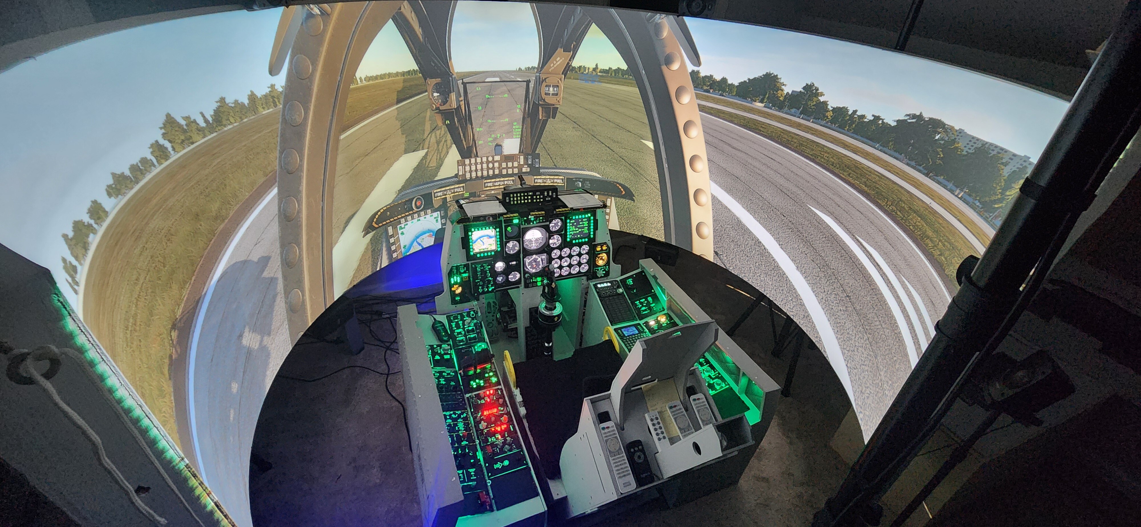
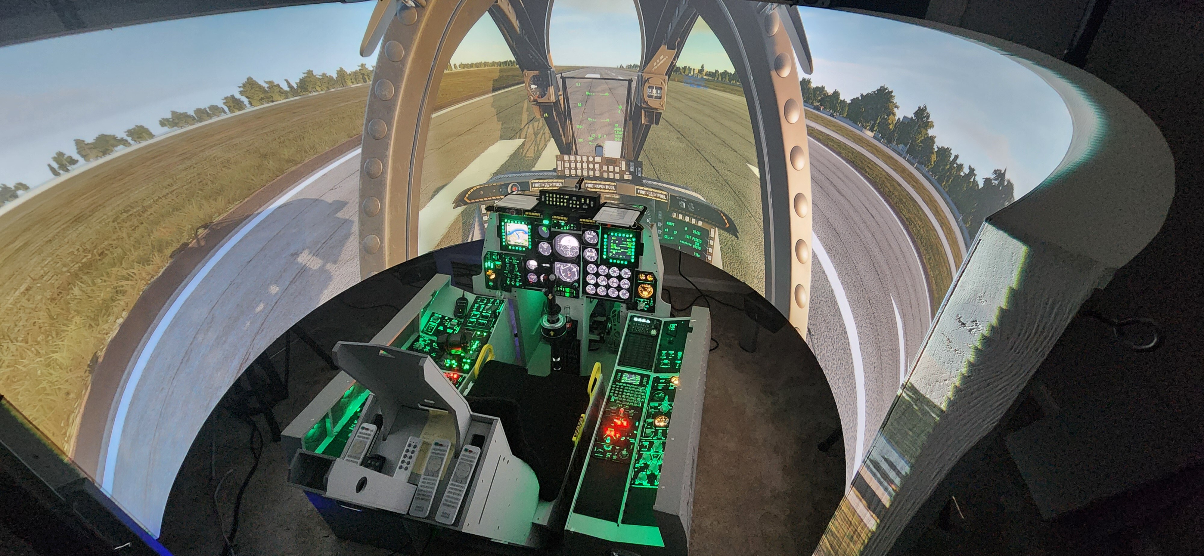
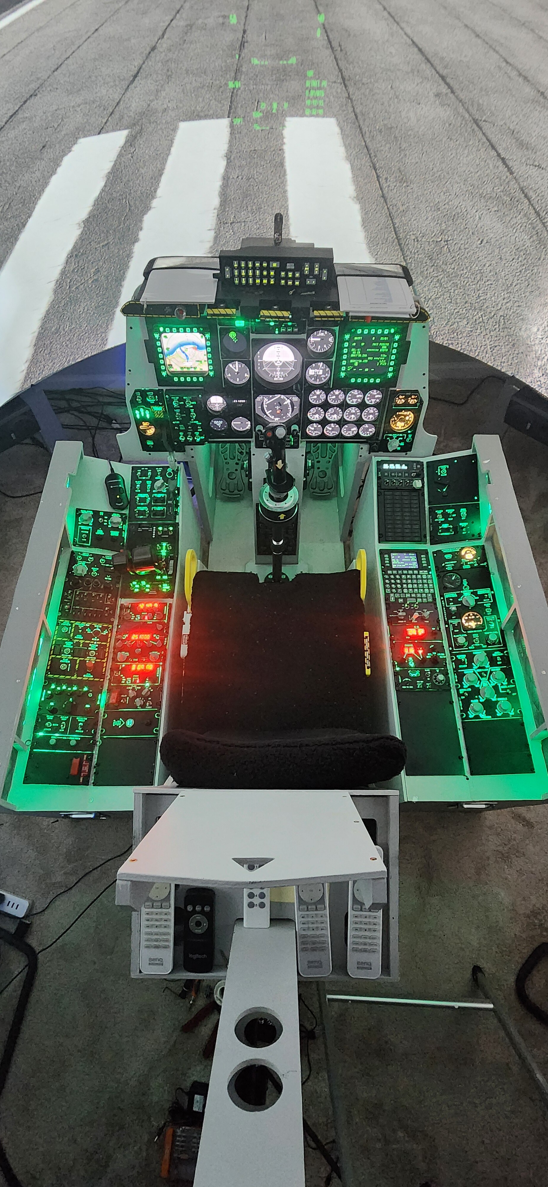
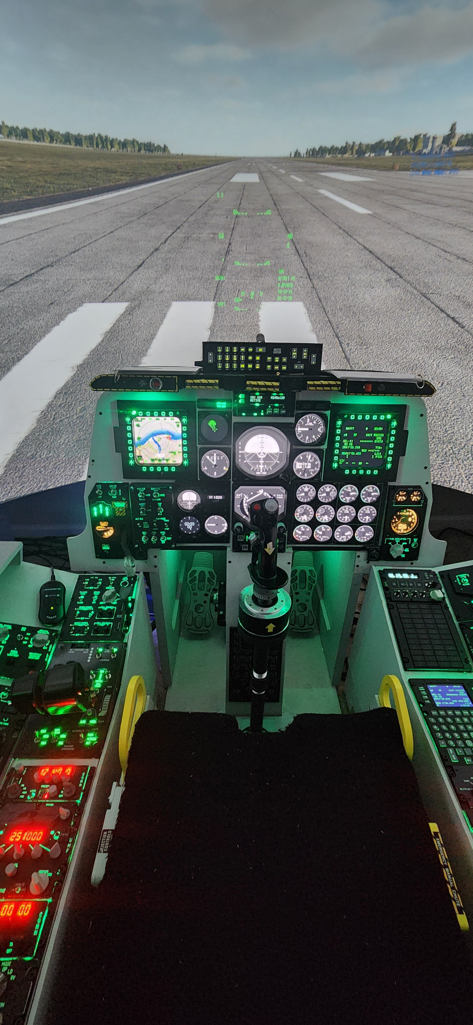
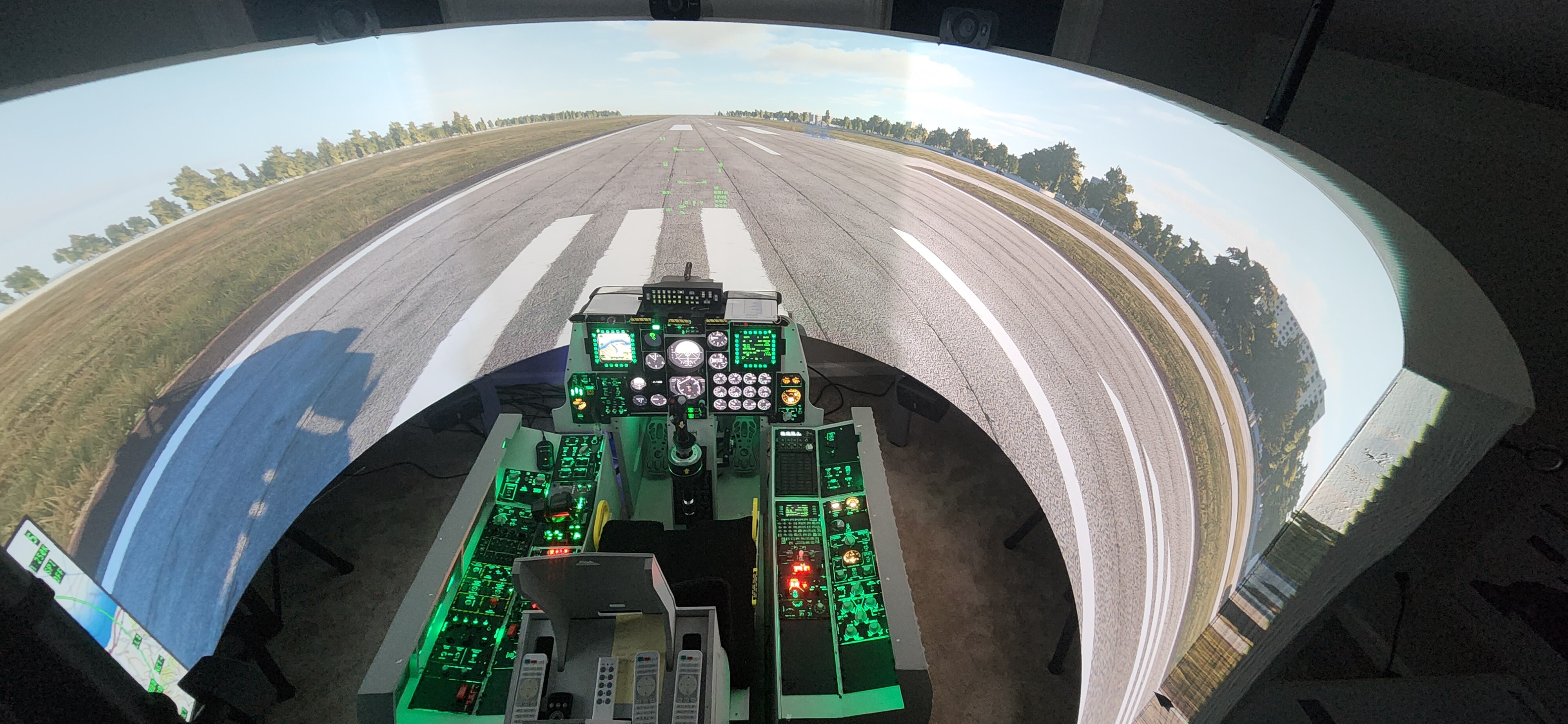
After about 6 years of off and on building, my A10 cockpit replica home simpit is finally complete. I still have a few extra things here and there that I want to add to the sim, but for the most part, it is complete. Pictures to come. When I began this journey, I looked around the forum for a thread like this and couldn't find one. 6 years later, I just did another search, and I still don't see one, so I thought I would start one and share with others some things that I learned during my build that I wish I had known when I first started, or before getting in to this endeavor. Please feel free to comment and expand on anything I missed or maybe I didn't run in to during my build, so that we may possibly help others. I'll also be posting all of my Arduino Sketches on another thread soon as well. Just a few ways I'm trying to pay it forward for all of the help I got from the amazing people on this forum. So in no particular order, here are some helpful tips from my sim building experience: 1) Time and money: If you're looking to build a full replica simpit of an aircraft/helicopter, you're going to need lots of it. I initially got my inspiration from The Warthog Project. During one of his earlier videos, he stated how much it cost him and that it took him about 5 years up until the point of his video. I thought nah, no way, I can do it a lot quicker than that, and probably cheaper. Nope, I couldn't have been more wrong. Obviously time and money are relative, some of us have more than others, but overall, understand you are getting in to a VERY long term project, and an expensive one. 2) Arduinos, Arduinos, Arduinos: I tried several different gaming control interfaces/ encoders in the beginning, Groovey Game Gear, Leo Bodnar, Arduino, etc. While they can all serve a purpose and will work, there's a reason why my simpit has about 13 Arduinos running it, and only Arduinos. I wish I had just saved my time, money and frustration and used only them from the start. Super user friendly and work really well with DCS and DCS Bios. 3) Wiring and connections: My simpit is a mix of individual wires, Ethernet cable (bundle of 8 wires) and breadboard jumper wires. I feel like they all can work, its just personal preference and maybe what you have on hand or can get for free or cheap. They each have pluses and minuses. I will say though that ethernet cables are great for panels with a lot of switches or knobs and keeping things neat and organized. The jumper wires are nice, but the male pins tend to break from time to time, which is very frustrating. As far as connecting whatever wires you choose, do yourself a favor and either solder the connections, or use screw type terminal blocks. Don’t use the jumper wires and just plug them directly in to the Arduino boards. At some point they WILL come out of their pin hole, or break in them. They’re really made for breadboard testing and only temporary use. So when you know what your connection is going to be, make it more of a permanent connection. Which leads me to my next lesson… 4) Building Your Panels and Wiring Them: Design them and build them so that 1) You can replace switches/encoders/ Pots, etc. and wiring down the road if need be, but yet 2) build them and wire them once. As in, do it right the first time. Don’t half ass it or wing it and say eh, that’s good enough. You WILL be rebuilding it or fixing it again at some point, trust me. Do it right and permanently the first time. I can’t tell you how many panels I had to go back and fix my laziness or half ass wiring or connections because things came loose, or broke. If I had just done it right the first time, that panel would have been done for good, and I wouldn’t still be trying to finish it or working on it and basically building it again, wasting A LOT of time. 5). Tools and Machines: Depending on how much of the simpit you want to build yourself, there are a few tools and machines that are invaluable. Assortment of wood working tools such as jigsaw, cordless drill and driver, Dremel Tool, Hot Glue Gun, Soldering Iron, Heat Gun, 3-D Printer, Laser cutter/engraver. By the time you buy all of the knobs, handles, covers, etc, you could have bought a 3d printer, made them yourself, saved money in the long run, and now you have a 3D printer, which has SO many more uses than just building a simpit. Same with a laser cutter/engraver. There are places out there on the internet that you can buy already made panels, or you can get a laser and build them yourself and save money in the long run. 6) Forums: This is without a doubt, the best advice I can give, use the forums. There is no way I would have been able to build my simpit without the help of some awesome people on these forums. Before starting this project, I had some pretty decent wood working skills, basic electronic skills, basic computer skills, and absolutely zero coding skills. I can't even count the number of times I was stuck in my build and came to the forum and either searched for an answer, or started a thread and asked for help. There are a lot of people on here that are absolutely amazing and know a hell of a lot, and they enjoy helping. Obviously YouTube is a great source for information as well, but this forum and the people here were absolutely instrumental in helping me complete my simpit. 7) MOST IMPORTANT: Have fun and don't forget to play DCS every now and then to remind yourself of why you're doing this! Hope this helps! Feel free to message me if you have any questions.
- 16 replies
-
- 11
-

-

-
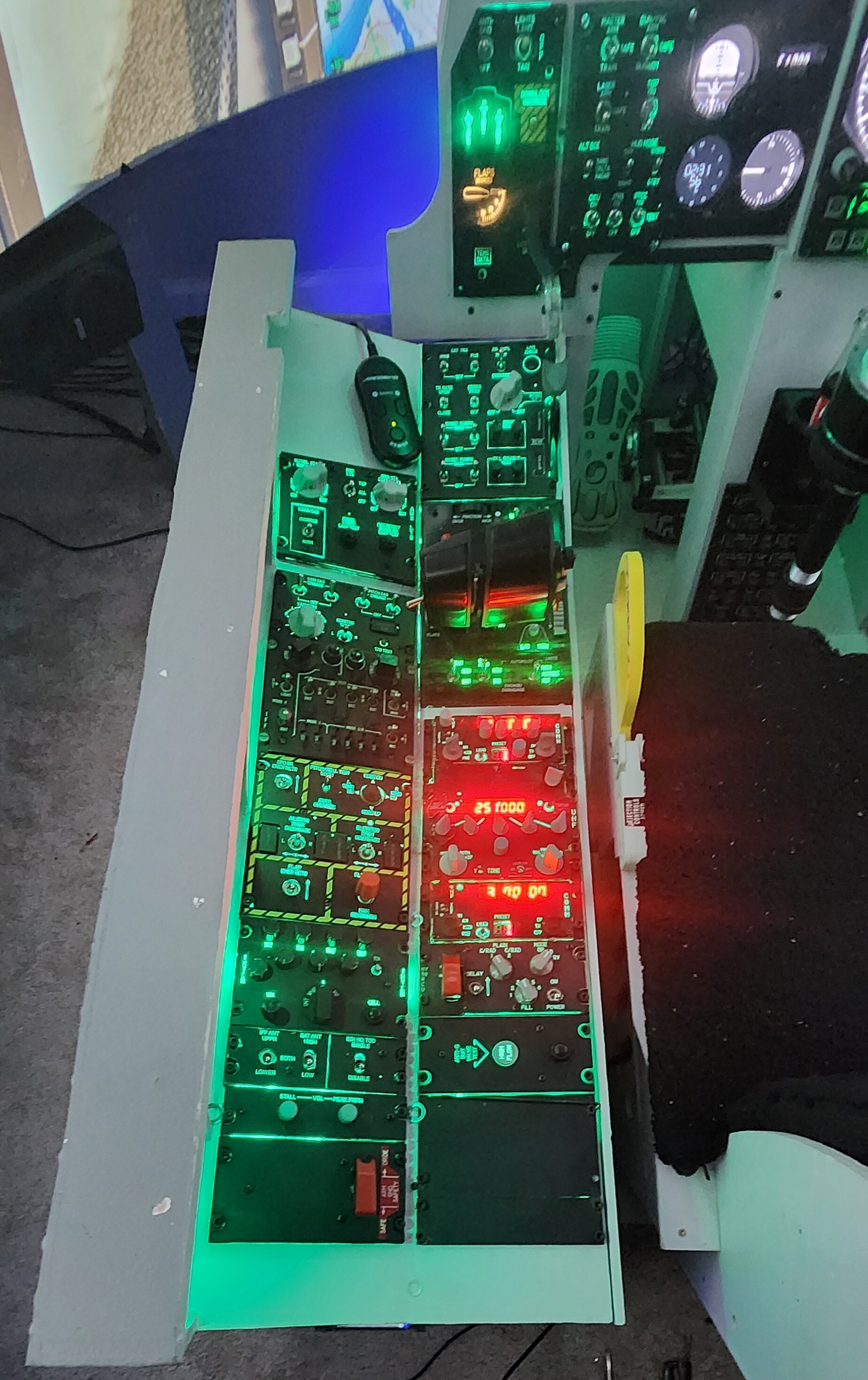
Hey guys, at the suggestion of @sharkfin61 to possibly help others, and its about time I pay it back for all the help I've gotten on here, I'm posting my Arduino Sketch for the A10 Intercom Panel. I can't take full ownership of this concept and idea though, that would have to go to The Warthog Project, as it is his. Unfortunately he didn't post his sketch anywhere that I could find, so I had to ask around for some help and created this one for the concept. A special thanks and shout outs to @Vinc_Vega and @No1sonuk for all of their time and help with creating this sketch. In the actual A10 aircraft, and thus in DCS, you unmute the individual channels by using push pull volume selector knobs. Those aren't exactly easily found for the common consumer and sim builder. The Warthog Project came up with the brilliant idea of using Rotary Encoders with switches, and LEDs for the Channel Back Lighting, so that when you push the encoder switch to unmute the channel, the LED illuminates, indicating the channel is "active" or unmuted. Push it again and the channel is muted and the LED light extinguishes. Brilliant. This way its easy to see which channels are unmuted and or muted. Here is the Arduino sketch to make all of that happen. This is also meant to be used in conjunction with DCS-BIOS: /* Tell DCS-BIOS to use a serial connection and use interrupt-driven communication. The main program will be interrupted to prioritize processing incoming data. This should work on any Arduino that has an ATMega328 controller (Uno, Pro Mini, many others). */ #define DCSBIOS_IRQ_SERIAL #include "DcsBios.h" DcsBios::Switch2Pos intCall("INT_CALL", PIN); const byte intModePins[4] = {PIN_1, PIN_2, PIN_3, PIN_4}; DcsBios::SwitchMultiPos intMode("INT_MODE", intModePins, 4); DcsBios::Potentiometer intVol("INT_VOL", PIN); // ----- INT Un-Mute input and output, INT volume adjustment ----- DcsBios::ActionButton intIntUnmuteToggle("INT_INT_UNMUTE", "TOGGLE", PIN); // INT switch on pin 10 for the INT Un-Mute switch typedef DcsBios::RotaryEncoderT<POLL_EVERY_TIME, DcsBios::FOUR_STEPS_PER_DETENT> FourStepRotaryEncoder; FourStepRotaryEncoder intIntVol ("INT_INT_VOL", "-1500", "+1500", PIN_A, PIN_B); DcsBios::LED intIntUnmute(0x1194, 0x8000, PIN); // a LED shows if the volume adjustment is active DcsBios::ActionButton intAimUnmuteToggle("INT_AIM_UNMUTE", "TOGGLE", PIN); // INT switch on pin 10 for the INT Un-Mute switch FourStepRotaryEncoder intAimVol ("INT_AIM_VOL", "-1500", "+1500", PIN_A, PIN_B); DcsBios::LED intAimUnmute(0x11a6, 0x0004, PIN); DcsBios::ActionButton intFmUnmuteToggle("INT_FM_UNMUTE", "TOGGLE", PIN); // INT switch on pin 10 for the INT Un-Mute switch FourStepRotaryEncoder intFmVol ("INT_FM_VOL", "-1500", "+1500", PIN_A, PIN_B); DcsBios::LED intFmUnmute(0x119c, 0x8000, PIN); DcsBios::ActionButton intIffUnmuteToggle("INT_IFF_UNMUTE", "TOGGLE", PIN); // INT switch on pin 10 for the INT Un-Mute switch FourStepRotaryEncoder intIffVol ("INT_IFF_VOL", "-1500", "+1500", PIN_A, PIN_B); DcsBios::LED intIffUnmute(0x11a6, 0x0008, PIN); DcsBios::ActionButton intIlsUnmuteToggle("INT_ILS_UNMUTE", "TOGGLE", PIN); // INT switch on pin 10 for the INT Un-Mute switch FourStepRotaryEncoder intIlsVol ("INT_ILS_VOL", "-1500", "+1500", PIN_A, PIN_B); DcsBios::LED intIlsUnmute(0x11a6, 0x0010, PIN); DcsBios::ActionButton intTcnUnmuteToggle("INT_TCN_UNMUTE", "TOGGLE", PIN); // INT switch on pin 10 for the INT Un-Mute switch FourStepRotaryEncoder intTcnVol ("INT_TCN_VOL", "-1500", "+1500", PIN_A, PIN_B ); DcsBios::LED intTcnUnmute(0x11a6, 0x0020, PIN); DcsBios::ActionButton intUhfUnmuteToggle("INT_UHF_UNMUTE", "TOGGLE", PIN); // INT switch on pin 10 for the INT Un-Mute switch FourStepRotaryEncoder intUhfVol ("INT_UHF_VOL", "-1500", "+1500", PIN_A, PIN_B); DcsBios::LED intUhfUnmute(0x11a6, 0x0002, PIN); DcsBios::ActionButton intVhfUnmuteToggle("INT_VHF_UNMUTE", "TOGGLE", PIN); // INT switch on pin 10 for the INT Un-Mute switch FourStepRotaryEncoder intVhfVol ("INT_VHF_VOL", "-1500", "+1500", PIN_A, PIN_B); DcsBios::LED intVhfUnmute(0x11a6, 0x0001, PIN); DcsBios::ActionButton intHmToggle("INT_HM", "TOGGLE", PIN); // INT switch on pin 10 for the INT Un-Mute switch DcsBios::LED intHmUnmute(0x11a6, 0x0040, PIN); void setup() { DcsBios::setup(); } void loop() { DcsBios::loop(); }
- 1 reply
-
- 3
-
-
-
Rotary Encoder W/Switch, LED and Arduino Help Please
Kenpilot replied to Kenpilot's topic in Home Cockpits
Thanks for all the help guys, the appropriate addresses for the LEDs did the trick and everything works great now. @sharkfin61 I will certainly do that, great idea. Hope it helps others! -
Rotary Encoder W/Switch, LED and Arduino Help Please
Kenpilot replied to Kenpilot's topic in Home Cockpits
Awesome, thanks so much Vinc. I'll give this a shot this weekend. Thanks again for your time!