

crash test pilot
-
Posts
211 -
Joined
-
Last visited
Content Type
Profiles
Forums
Events
Posts posted by crash test pilot
-
-
On 1/4/2023 at 10:13 PM, crash test pilot said:
I used 500 ohms variable resistors, and they are way too big. If you have a look into the datasheet for the ina122p chip you find a table for desired gain. As it just happened today that i ripped a cable from a load cell i have to rebuild - i will test some non-variable resistors between 20 and 200 ohm and report back for my findings.
In the end i used 180 ohm resistors - just what i dialed in my variable resistors.
-
Windows only sees 8 axes from one game controller. You can split your device into two virtual devices with software like joystick gremlin.
-
The Apem switches do have this, albeit they are a bit expensive... But sometimes you find them on the bay...
-
 1
1
-
-
-
-
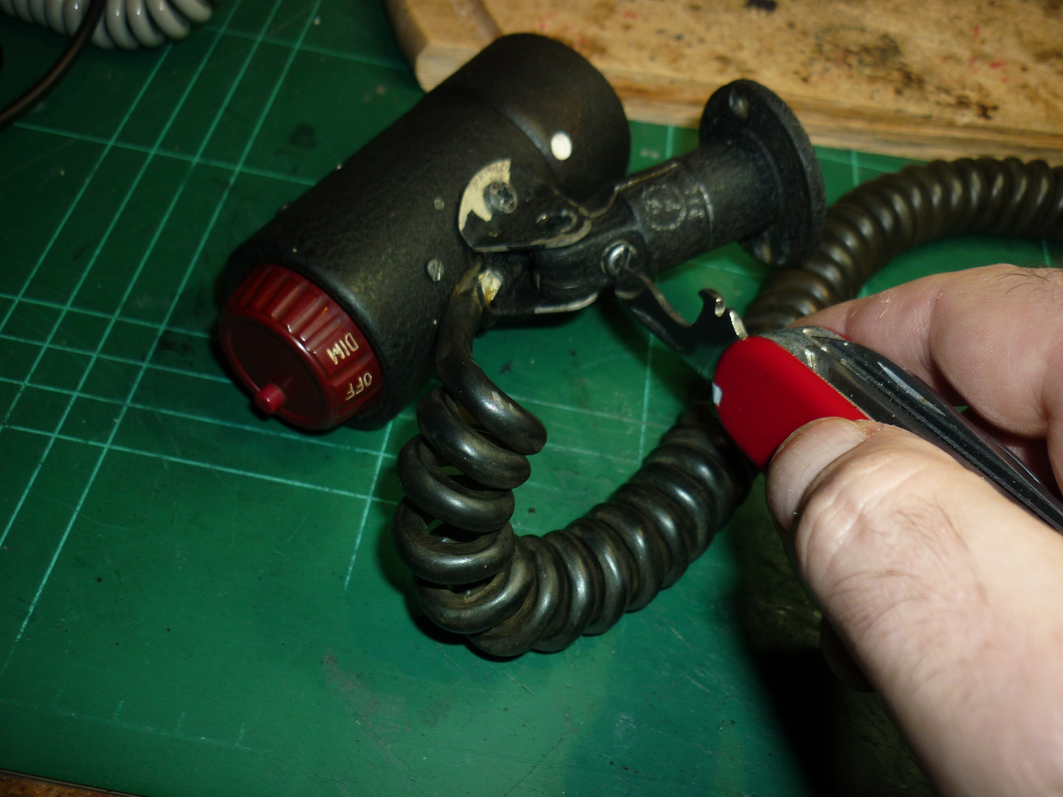
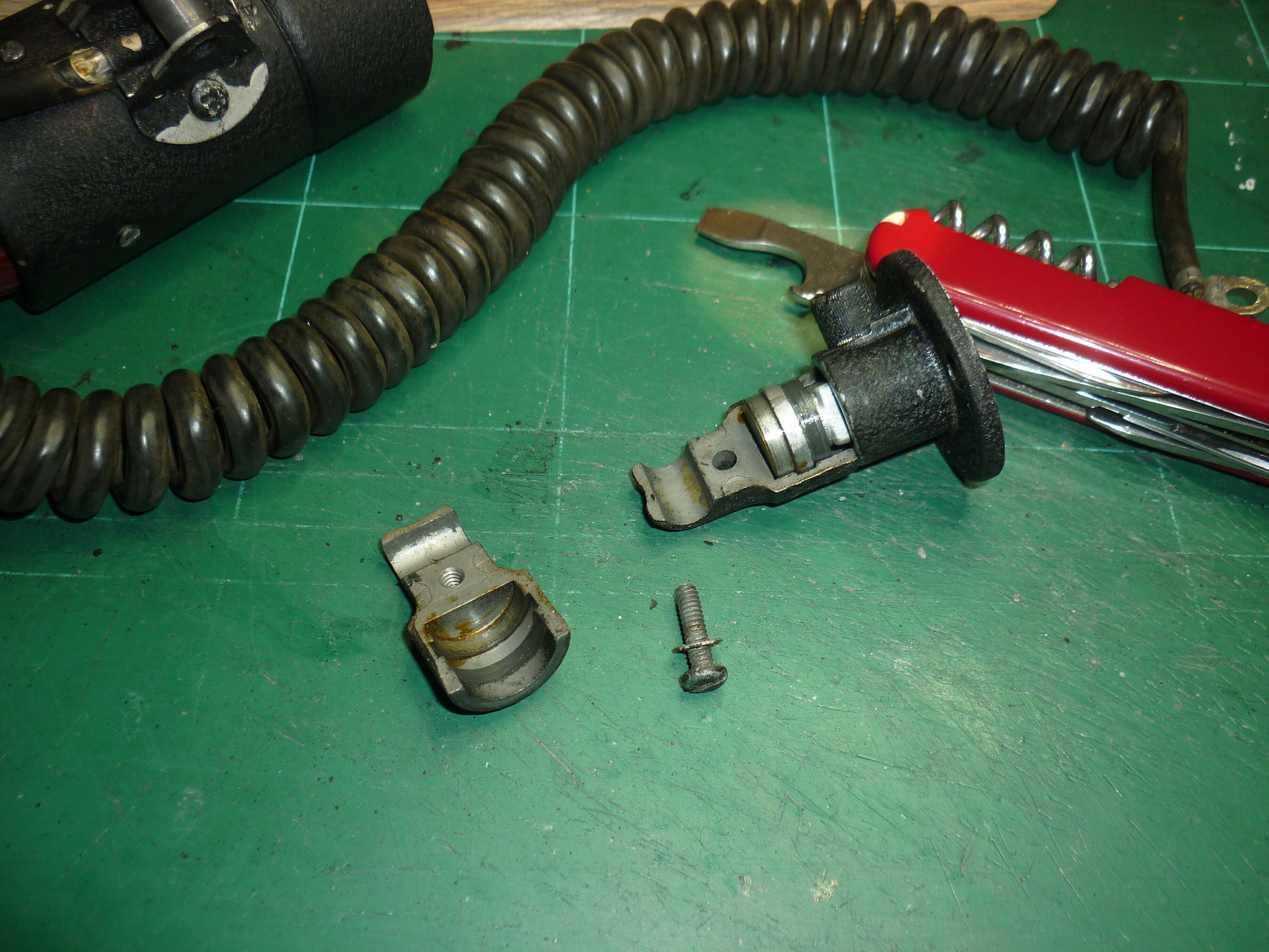
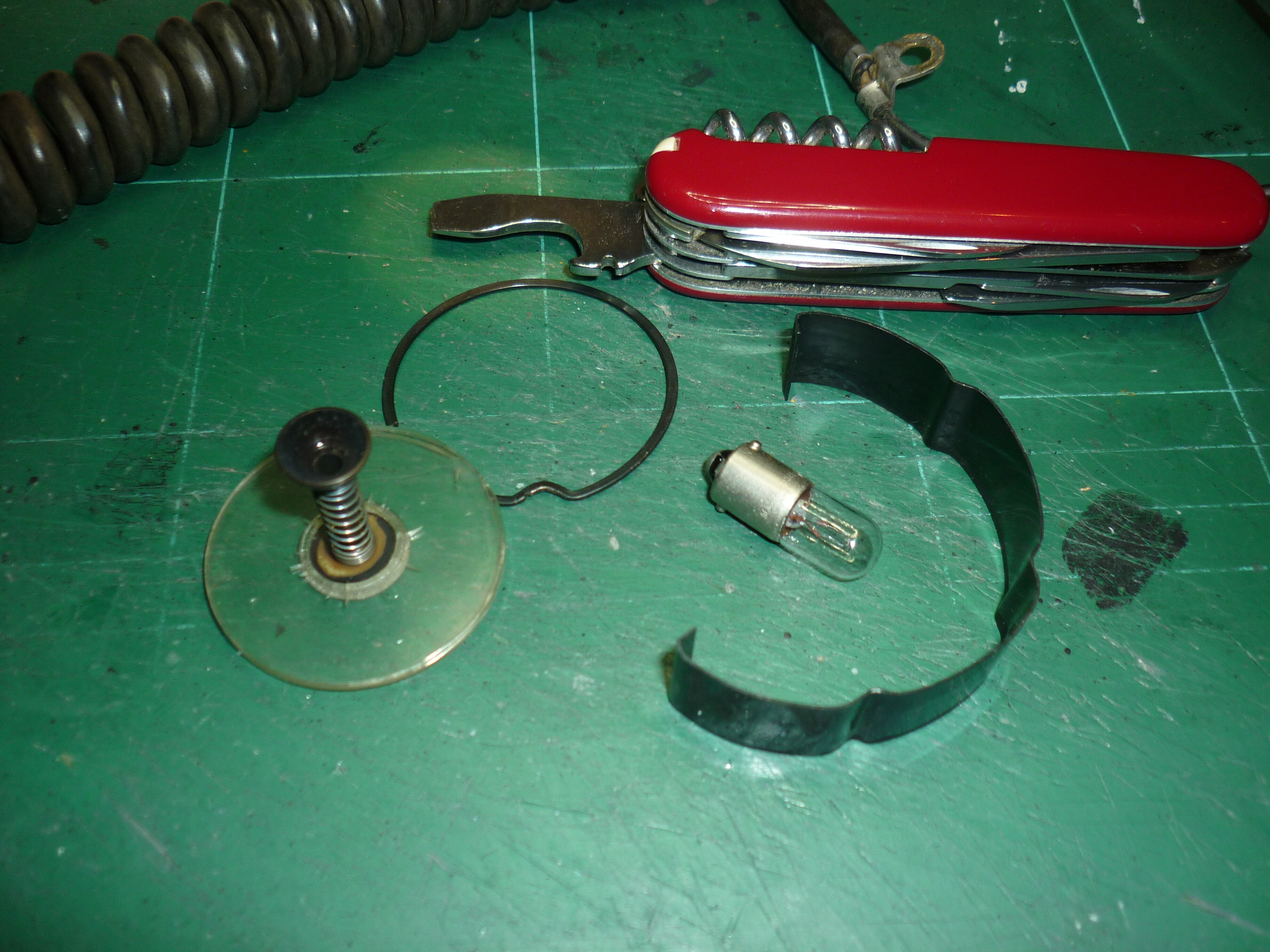
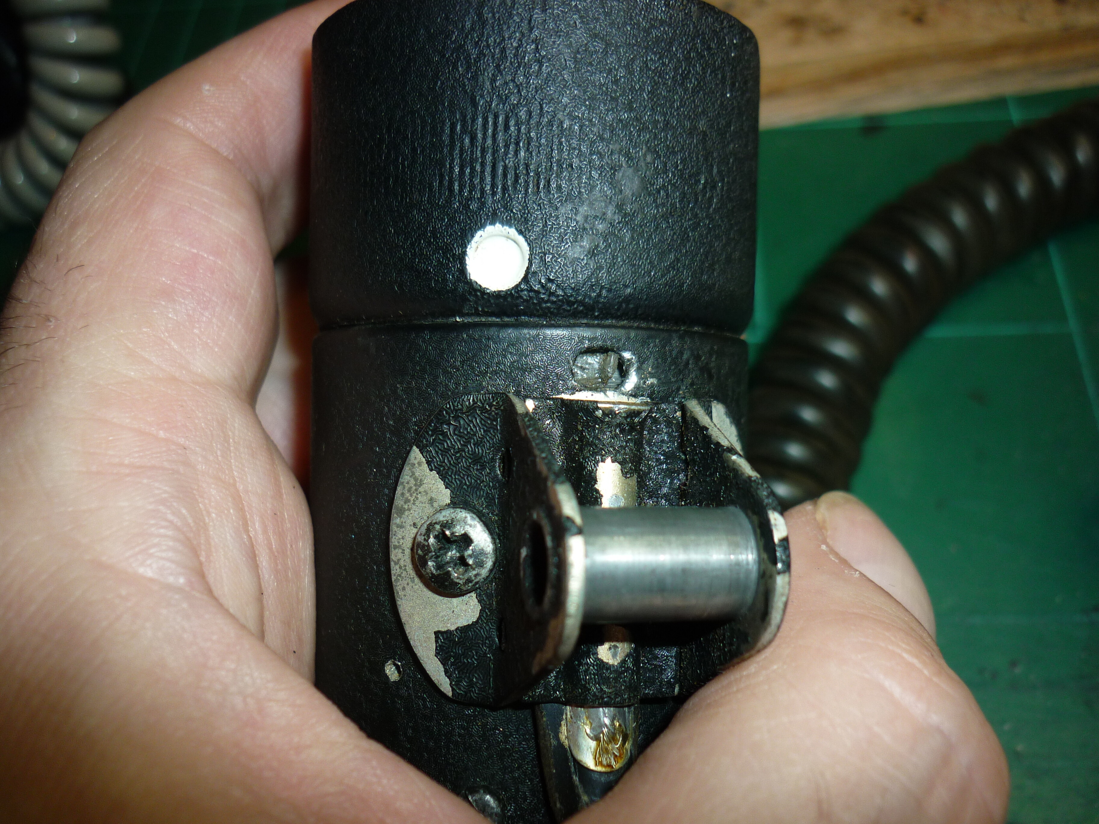
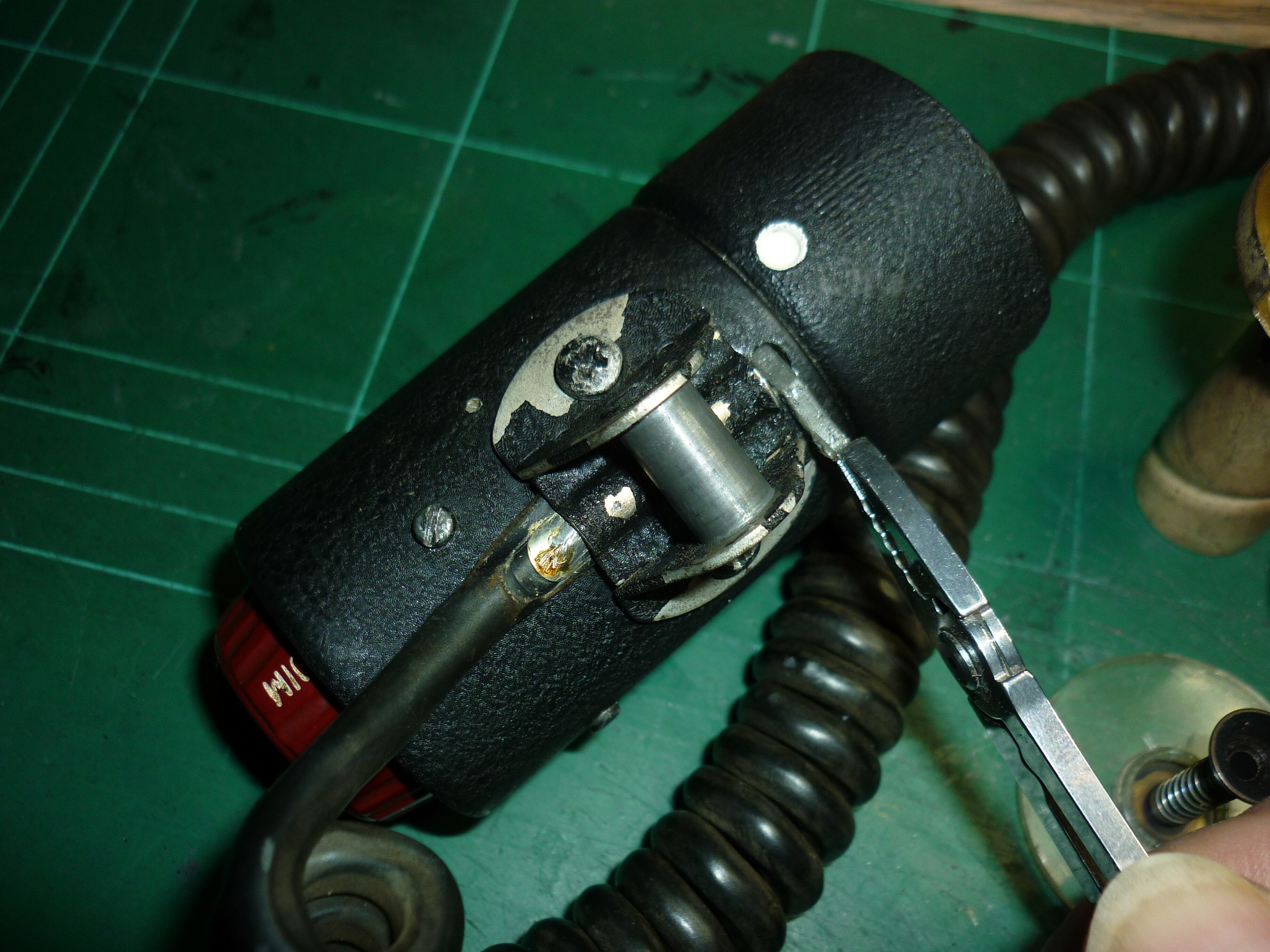
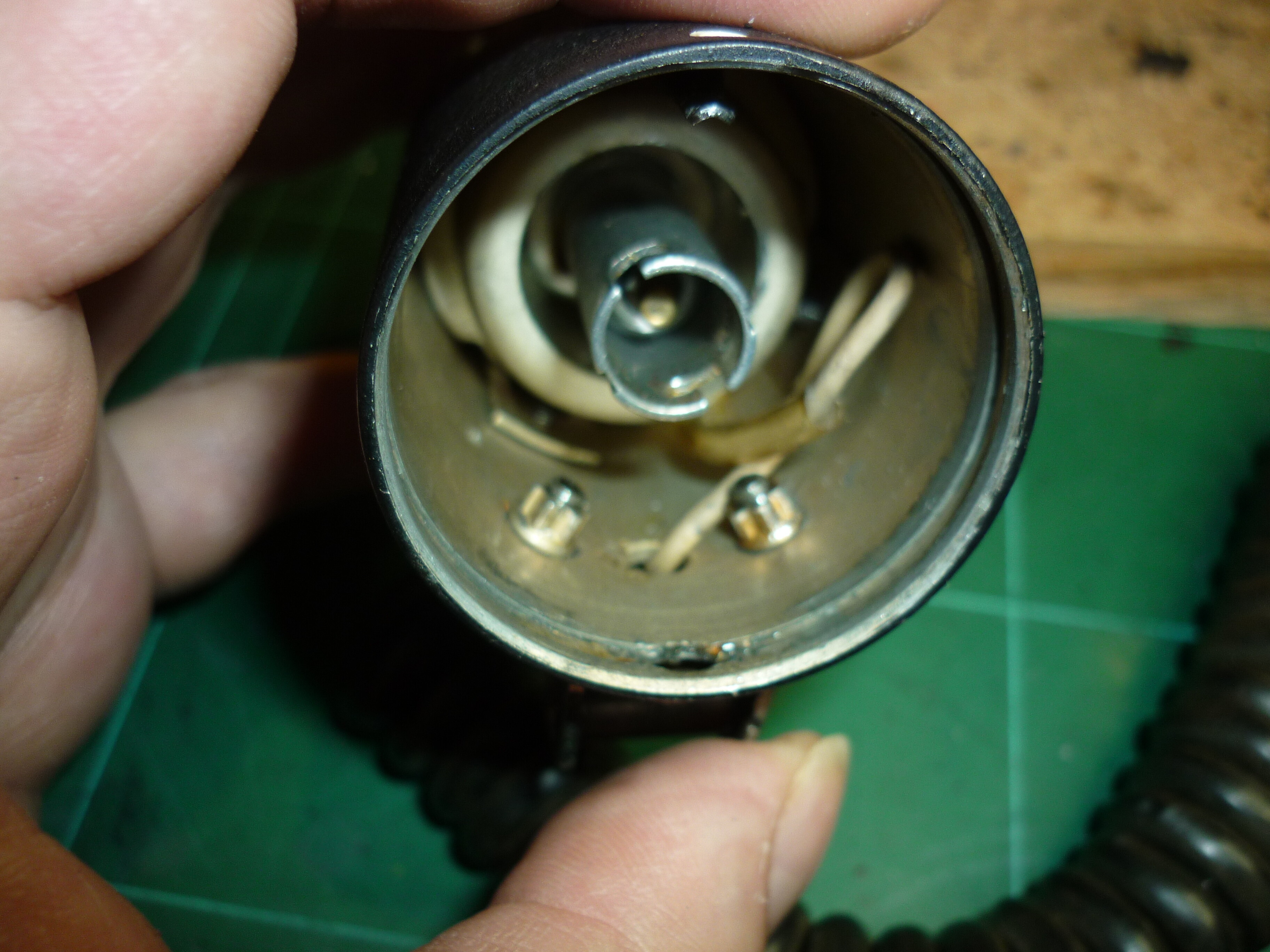
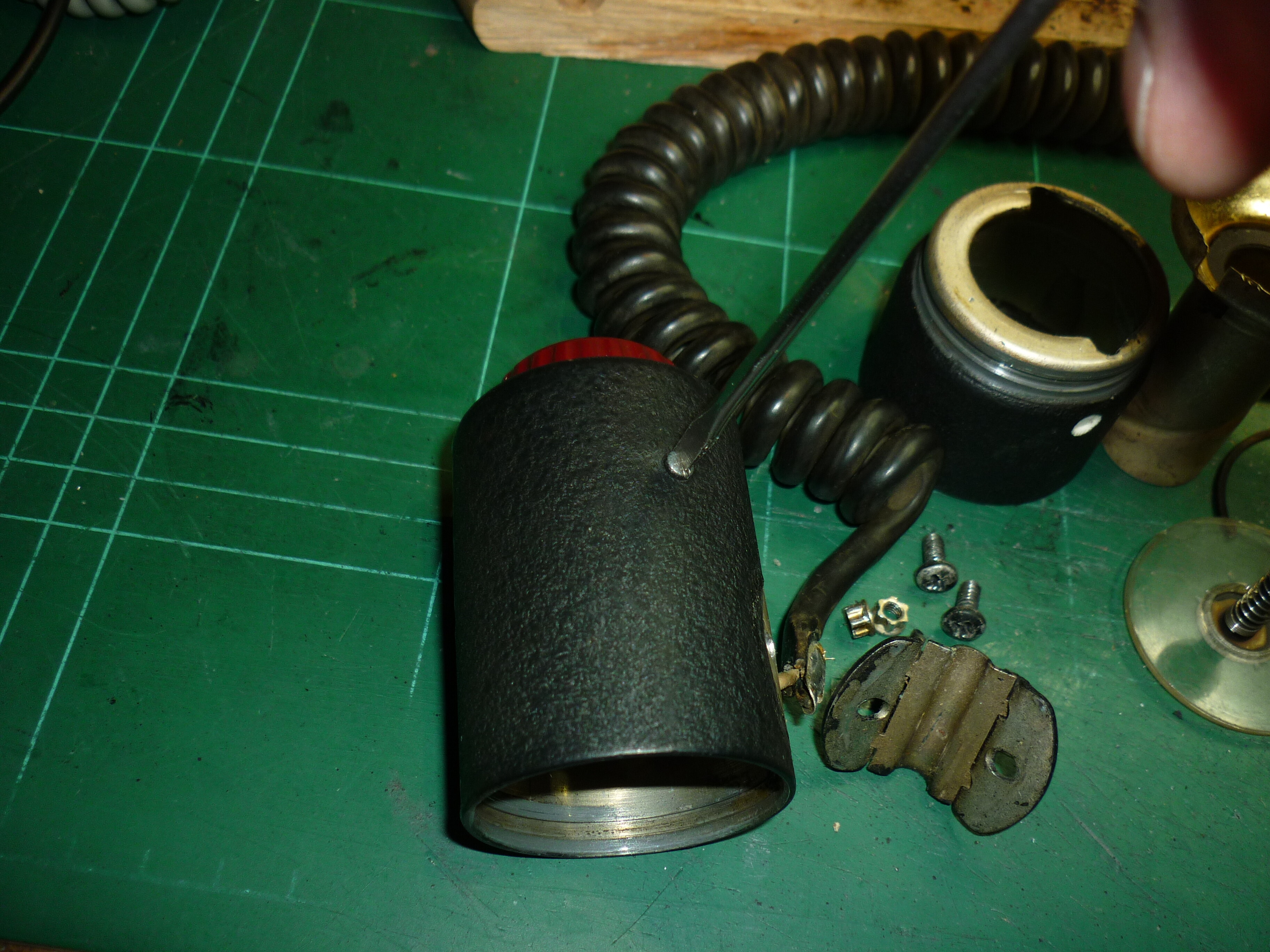
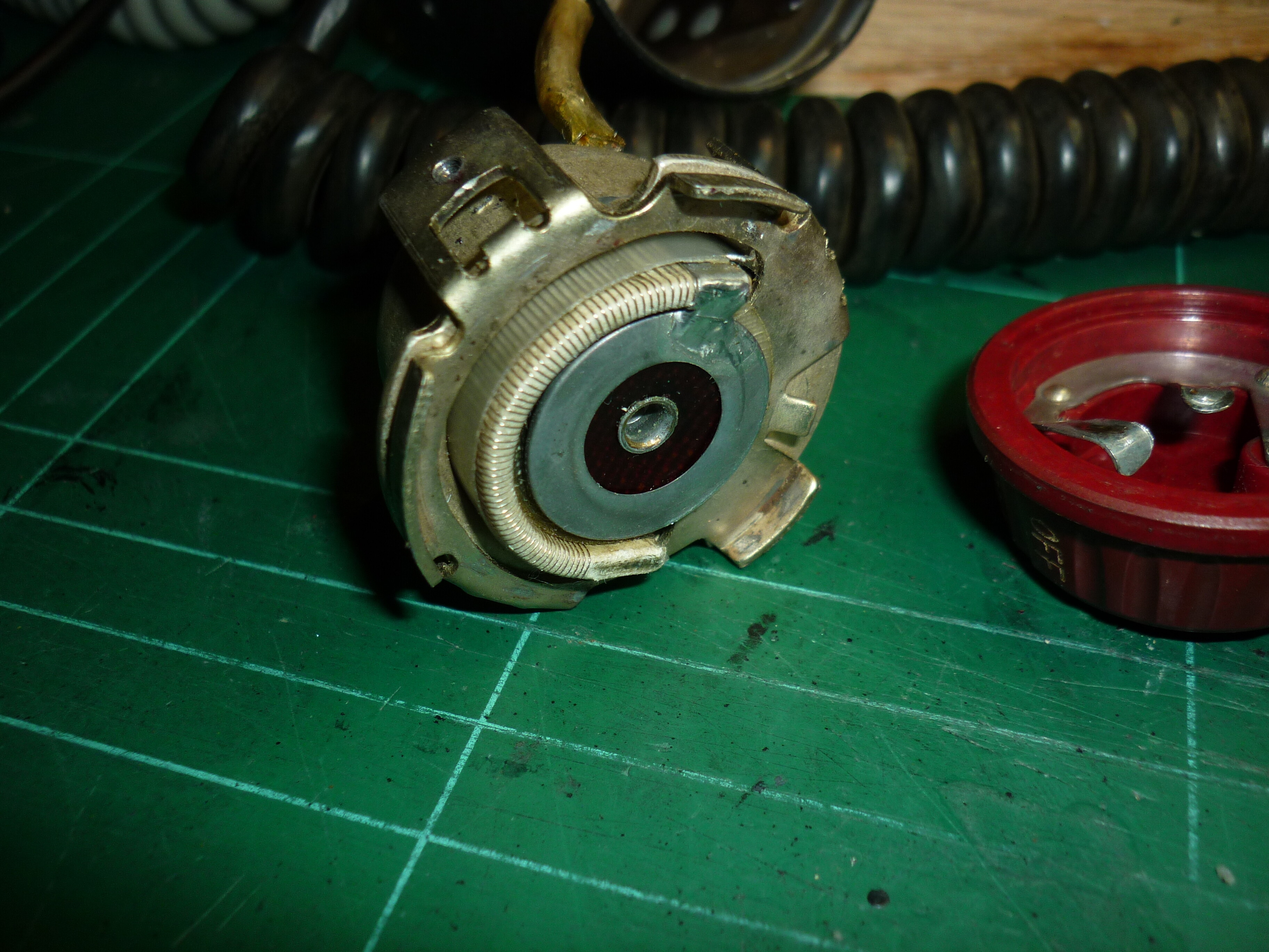
I managed to open and repair it with the help of someone on reddit. Here are some pics of the disassembly:
-
1
-
-
Yes, it was sold as scrap. I was very delighted to see it light up - when i shake it. The 28v bulb was already replaced by a 12v bulb, which i really appreciate, because my homecockpit has no 28v - only 12 and 5v. If i cannot open it without destroying it i may better leave it as is.
-
Hi! I managed to to aquire an original grimes cockpit utility light. https://imgur.com/gallery/ZSVYSzH Sadly there seems to be a bad connection somewhere in there. I fail to open it to have a look and all i found online are manuals to purchase. Can someone point me in the right direction on how to open this little gem in a non-destructive way to get it fully working again? I can take out the lens and the bulb, and the little screws at the back - the dimmer unit the rotates freely but does not come out. The screws at the pivot do not come out sadly. Thanks!

-
There WAS the super taurus from winwing, which was about 98% actual f-18 throttle, but it is no longer in production and sold out a long time ago. I have seen many people asking to buy a used one , but no one selling one. Rumour says winwing is working on a succesor, but dont take my word for it. At the moment your best option is to build one yourself - openhornet project has a lot of plans to offer.
-
2
-
-
If you have a 3d-printer (or acess to one) you could use this:
https://www.thingiverse.com/thing:4543158
Alternatively you could use the alps rkjxm/rkjxl/rkjxt switches or these:
https://pcflights.com/navigation-switch-joystick-2-axis-4-ways/
-
1
-
-
I always use the latest, dcs-bios doesn not seem to care about open beta or stable...
-
1
-
-
The zip file contains all you need. Under releases you can find older versions (if you ever need them) and you can download the arduino-library (DCS-BIOS_0.7.48.zip) if you want to program your modules on a computer without dcs.
-
Any news on this? Just found the arc-210 display in the newest dcs-bios reference and wanted to get out the tank hunter again, but nothing works. The "old" Hog works in with dcs-bios, but not the new one.
-
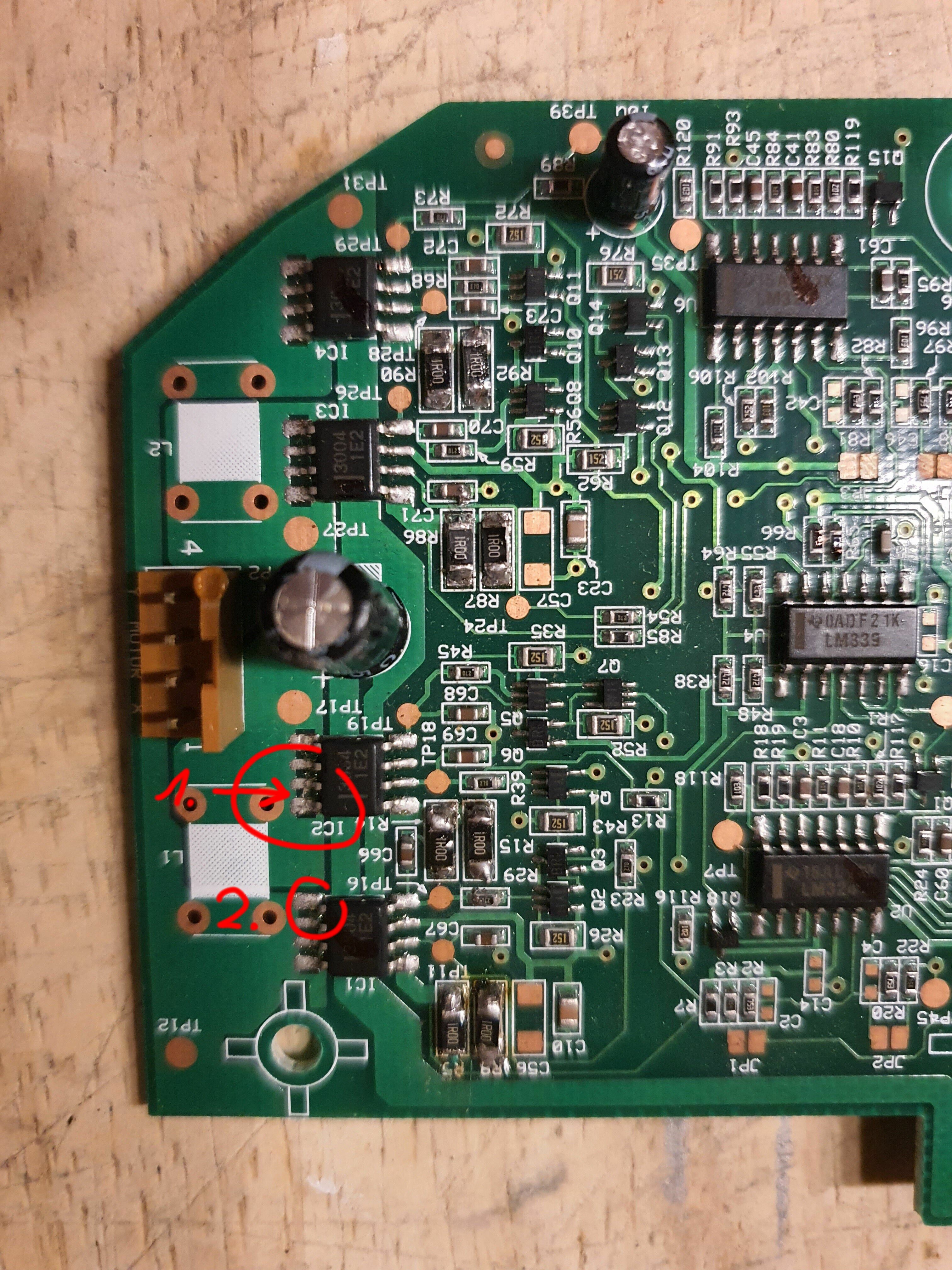
Hi! I was looking at your pcb and two spots hit my eye:
1. Is this a shorting?
2. Is this contact ok?
Maybe you check with a multimeter... Good luck!
-
1
-
 1
1
-
-
Hi Lesthegrngo, the hub version has not seen updates in 4 years. Active Fork is the Flightpanels one:
https://github.com/DCSFlightpanels/dcs-bios
-
-
Warthog base gimbal is made from plastic, it will break with such a long extension. Better get a base with metal gimbal like virpil, vkb or winwing.
-
4 minutes ago, Kenpilot said:
I just got back to working on my simpit and noticed the original DCS BIOS is no longer supported. I'm trying to update all my sketches with the new language and current DCS BIOS software. For the A10 CMSP LCD display, which I have wired to an arduino MEGA, in the sketch language, where do I put the pin numbers for the SCL and the SDA inputs/wires? Most sketches have PIN, where you put the arduino pin number, but the current language doesn't have that. This is the current language for the CMSP Display Line 1 and Display Line 2:
DcsBios::StringBuffer<19> cmsp1Buffer(0x1000, onCmsp1Change);
DcsBios::StringBuffer<19> cmsp2Buffer(0x1014, onCmsp2Change);
Anyone have any idea?
Take a look at your Mega: Pin 20 and 21 should be labeled SDA and SCL. You dont need to give a pin number.
-
Hi Bucic, I do not know anything about the boards you posted. About the allegro hall sensors: Do you have any experience with reichelt.de? I do not know about transport fee to poland but the sensors itself are dirt-cheap:
The problem with the adc in the stm chips is not the chip itself but the absence of filtering capacitors. Better get some no matter if you go with or without external adc...
-
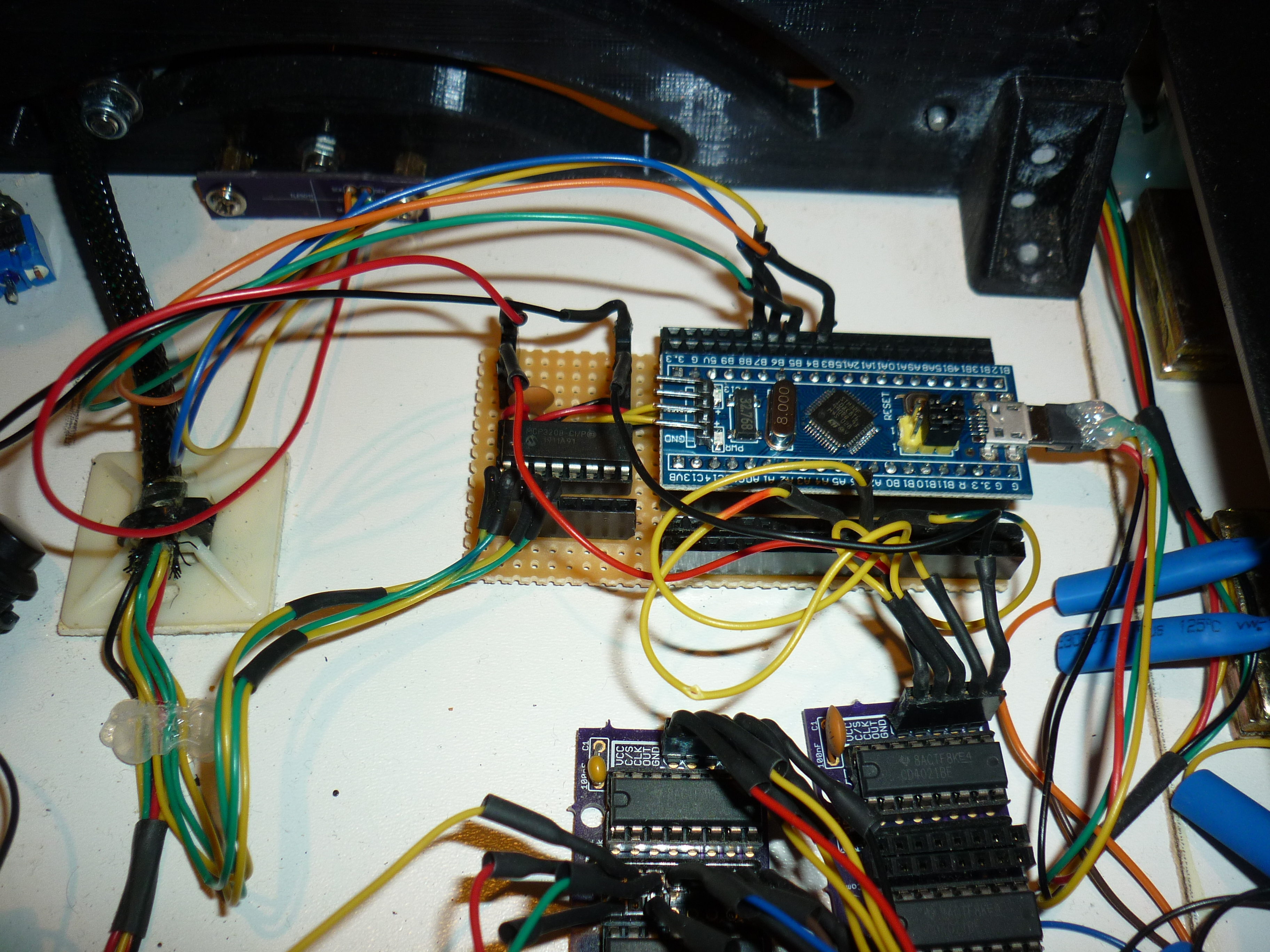
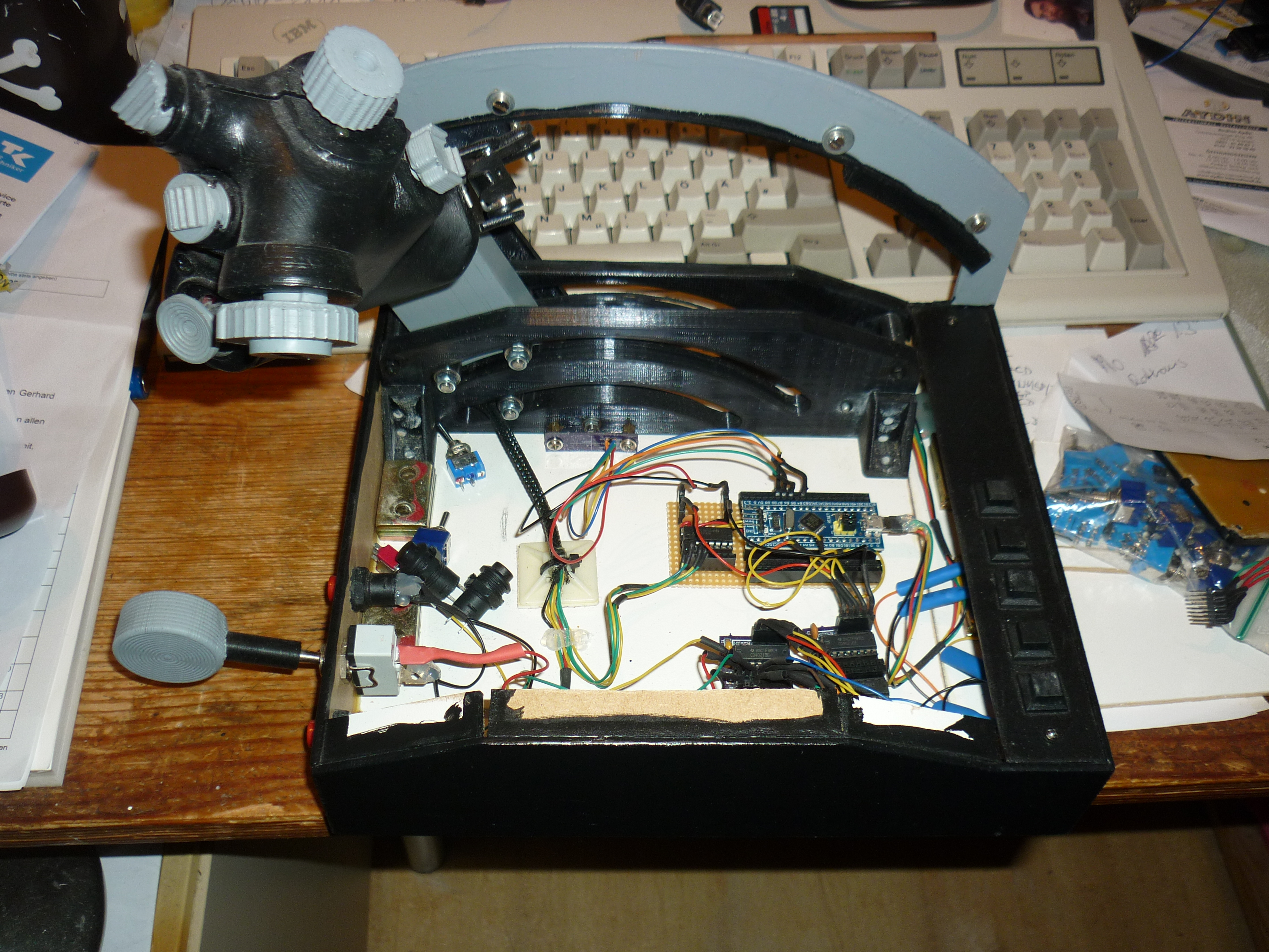
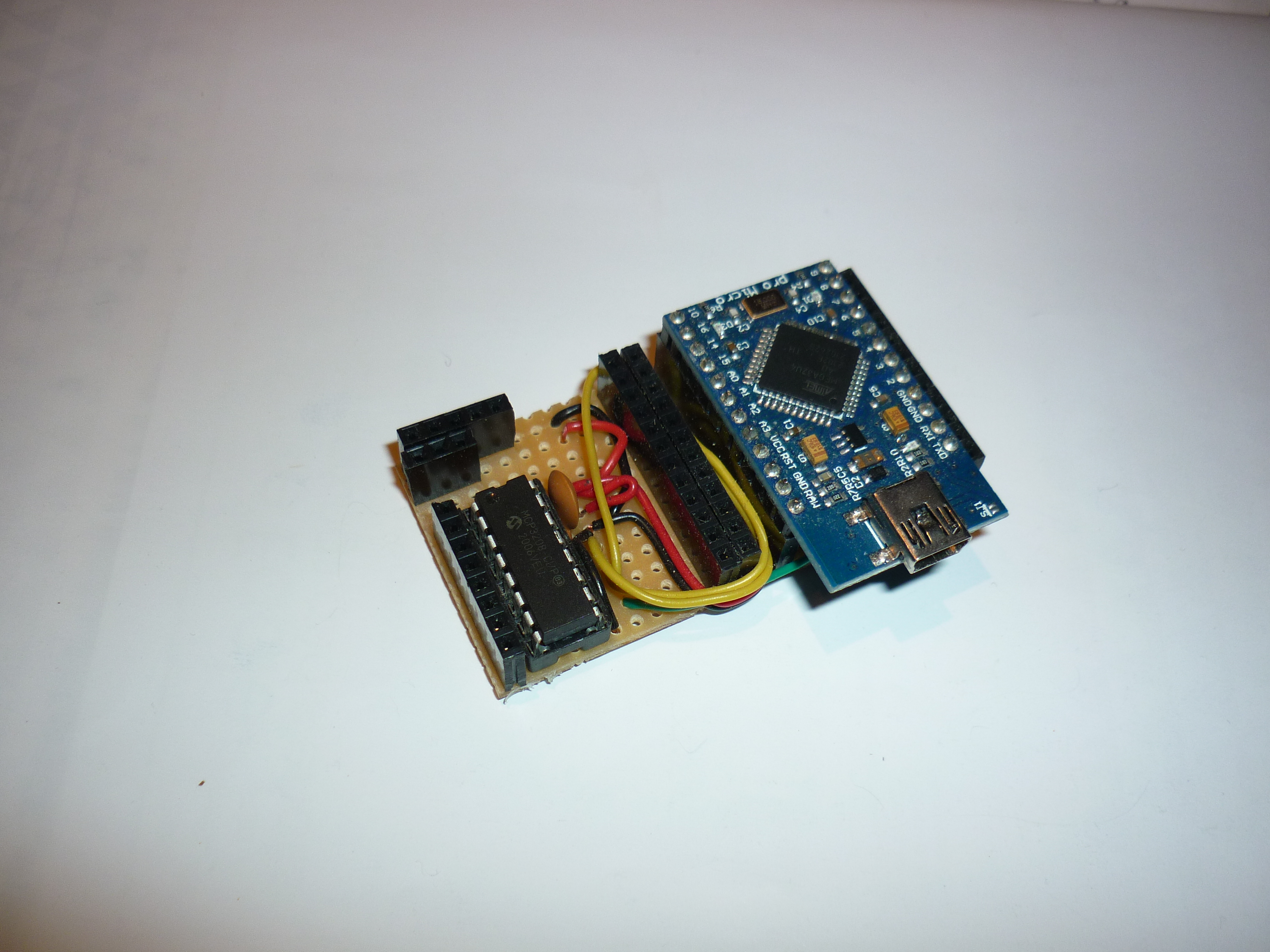
Here are some pics from my throttle project with freejoy. A tle5011 for the main axis, a mpc3208 adc for all other axis and shift registers for all buttons.

-
Lets continue this in the freejoy thread. I wrote you a message there.
-
1
-
-
Hi Bucic! I got one of these:
https://www.ebay.de/itm/402318508813?var=672304534726
You need the st-link programmer (or a usb-uart converter) for writing the firmware before first use. Afterwards you can write configuration data via usb.
-
As promised, here a fritzing diagram and a pic:
Green wire is mosi, yellow is miso, orange is clock. Blue is CS and can be any pin.
-
2
-
1
-
-
Bluepill is a nickname for the STM32F103C8 boards (used for freejoy) because of their blue pcb and as a reference to the matrix films... And because of cheapness their analogue inputs tend to pick up a lot of noise and need filtering so the higher resolution gets turned down by that. External ADCs are not really difficult to use with either mmjoy or freejoy. Here are links to the wikis:
https://github.com/MMjoy/mmjoy_en/wiki/Connecting-basic-inputs-and-setting-up-software
https://github.com/FreeJoy-Team/FreeJoyWiki/blob/master/eng/Connecting-analog-axes-to-MCP320x.md
Currently not at home, can post a fritzing diagram and pics later.
-
1
-
1
-


AHCP Button Box wiring
in Home Cockpits
Posted · Edited by crash test pilot
No. As all your switches are connected to ground, your microcontroller cannot discern between any switch on the same row. See Example below:
All connections must go to digital pins (most analoge pins are usable as digital) so when sending voltage to the column it can be sensed on the corresponding row. Diodes are not shown but as you want to use several switches at the same time they are needed. It does not matter if they are attached to the columns or the rows. as long as you pay attention to the direction of the flow of electricity (comes from the column and goes to the row). Three-position-switches may be confusing at first, as each is connected to two rows and one column (or two columns and one row) but with a little understanding of the principle of matrixes you will soon master this. Have fun and something to read:
http://pcbheaven.com/wikipages/How_Key_Matrices_Works/