I have just looked through this more carefully. What are you using for the LEDs? Is it a pre-made board with eight digits and a TM1637 driver?
In your code comments you say there should be seven digits, but the pictures show eight digits.
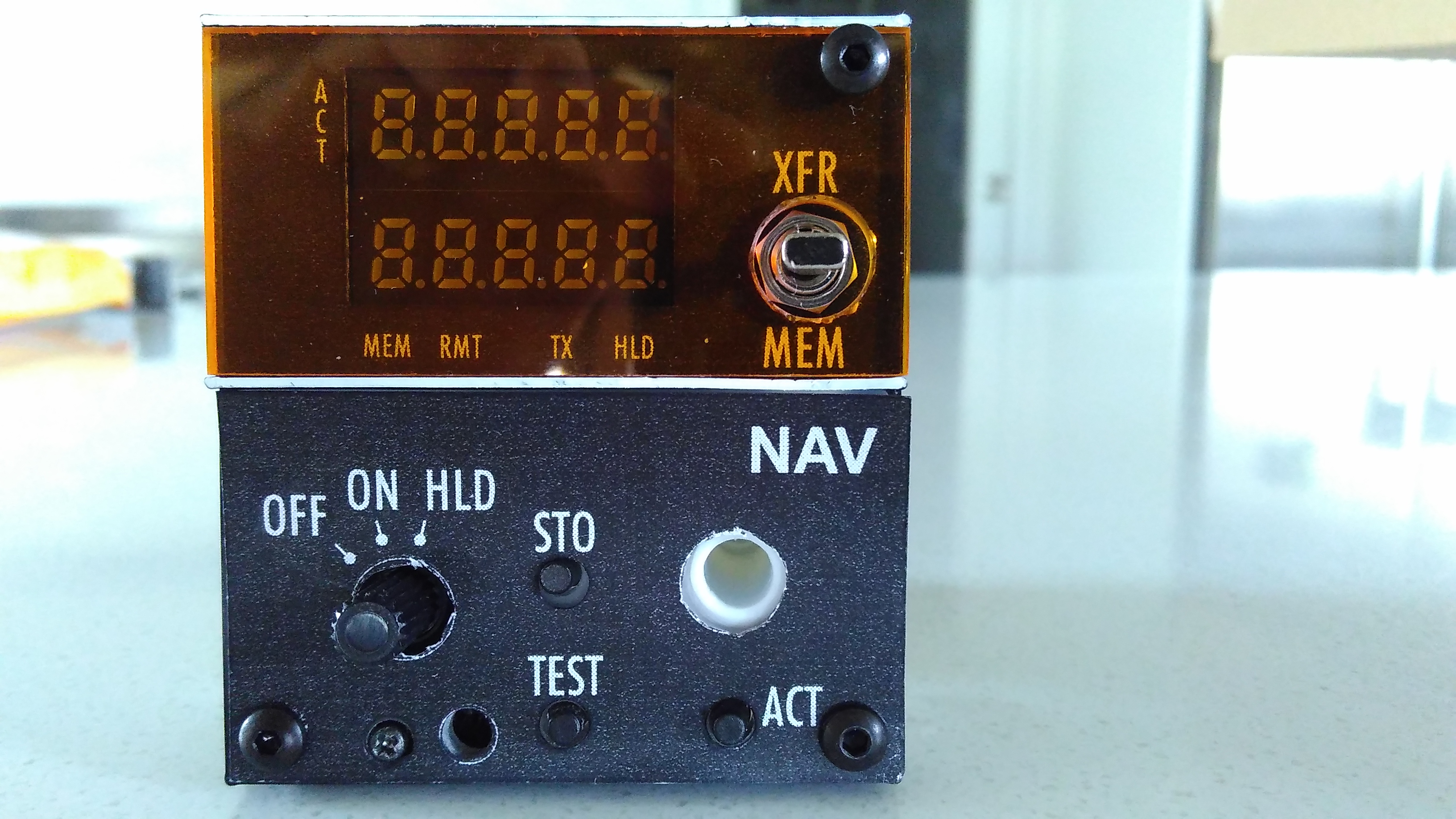
Then you are using the Holtek HT16K33 to drive the LEDs at the left side (one green, one RGB), right?
I am using the HT16K33 to drive two 5-digit 7-segment displays. The chip will drive eight 16-segment displays, so if I consider two 7-segment displays to be one 16-segment display then I am driving five 16-segment displays. Of the remaining three, two are unused, and one is used to drive five status LEDs.
Then I am using the keyboard input capability of the chip to read the switches on the front panel.
The original unit has a volume control. I am fitting one, with a 10K pot, but I won't connect the pot. The unit also has a light sensor, which I am fitting (because it finishes off the look of the unit) but I won't connect it. If I did I'd probably use an ADS1015 (or ADS1115) I2C ADC. They have four inputs each so two of those will let me hook up six volume controls and at least one light sensor (although not all of the units have volume pots, maybe five of them). Then everything is on I2C and can be driven by any I2C controller (such as a Raspberry Pi).
Waiting for parts...