loubial
-
Posts
27 -
Joined
-
Last visited
Content Type
Profiles
Forums
Events
Everything posted by loubial
-
 I turned my electronics Cougar and I replaced it with 2 cards Leo Bodnar: BU0836A (12 bits 4096 steps) embedded in the stick (buttons + 2 axis) BU0836 (10 bit not 1024 steps) embedded in the trottle (buttons + 5 axis) off course, each are connected via USB. Cards connected individually works perfectly, buttons and axis.... but connected all, buttons 836A are not operative, only axes are working... while the 836 continues to function properly. If I unplug the 836, the 836A becomes operational ... but if I plug again, problem ! All this found in the windows game controller. In A10, the cards are identified, each with a different number. ... but the 836A buttons do not work . I tried to change cluster USB, bad results. Does some one an idea? I am under seven 64pro, it is the driver of the OS that support the card.
 -
That's right, you start the manufacture? I receives my kinetrol dampers at the end of july...:pilotfly:
-
If you continue like that, my wine cellar will be too small when we meet!
-
I'm very happy to be the man you describe. Thank you for this dream... but the reality...
-
I've tried to find a web shop but no way world wide ! I've bought my KD on Kinetrol France (Distributor - < 100 € piece) You can find kinetrol distributor addres here The ideal solution is to get an adjustable vane dashpot (KD model) (which I have done) to calibrate the proper damping coefficient. Study kinetrol documentation and ask me my choice range parameters for my own using (I'm finishing blue print)
-
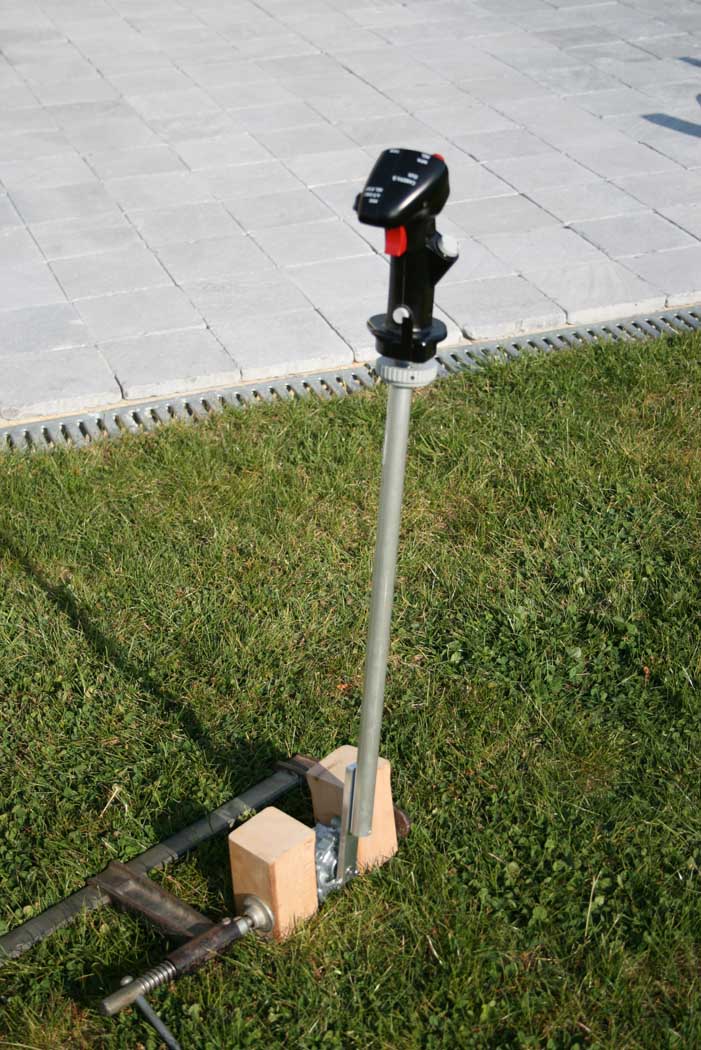
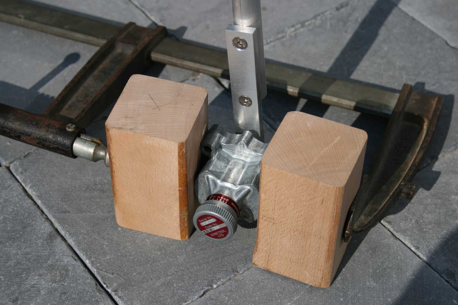
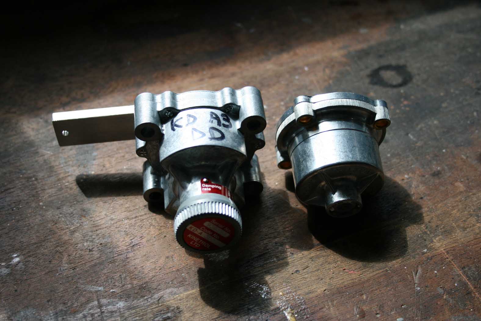
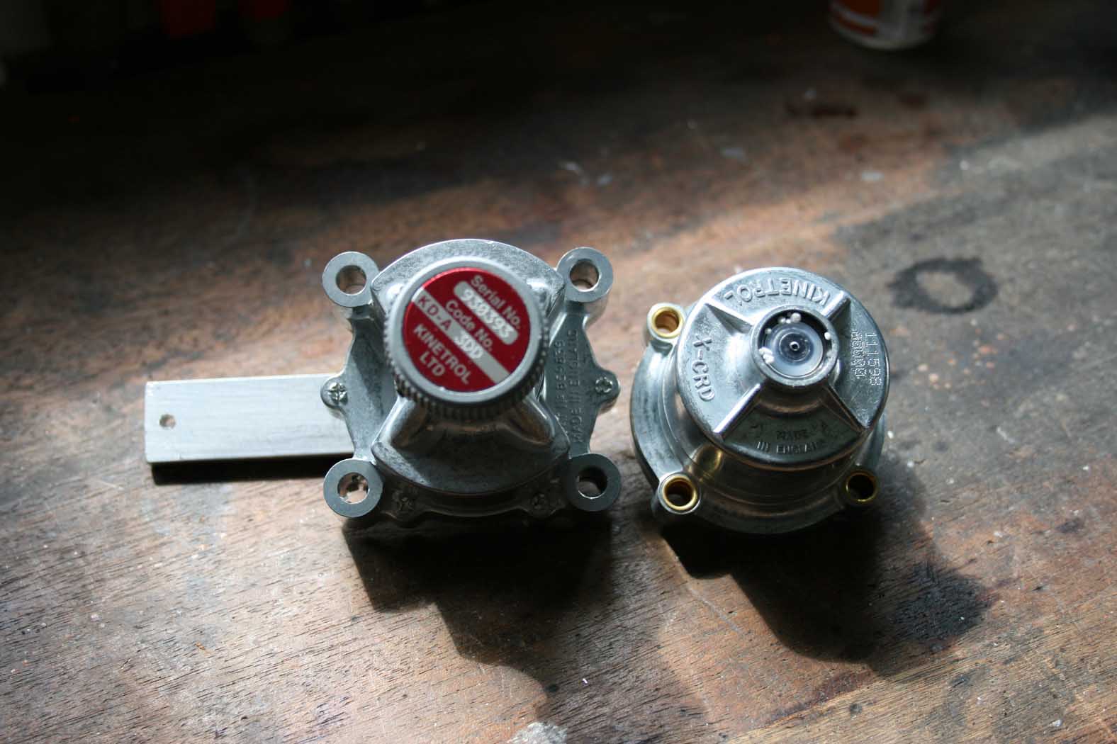
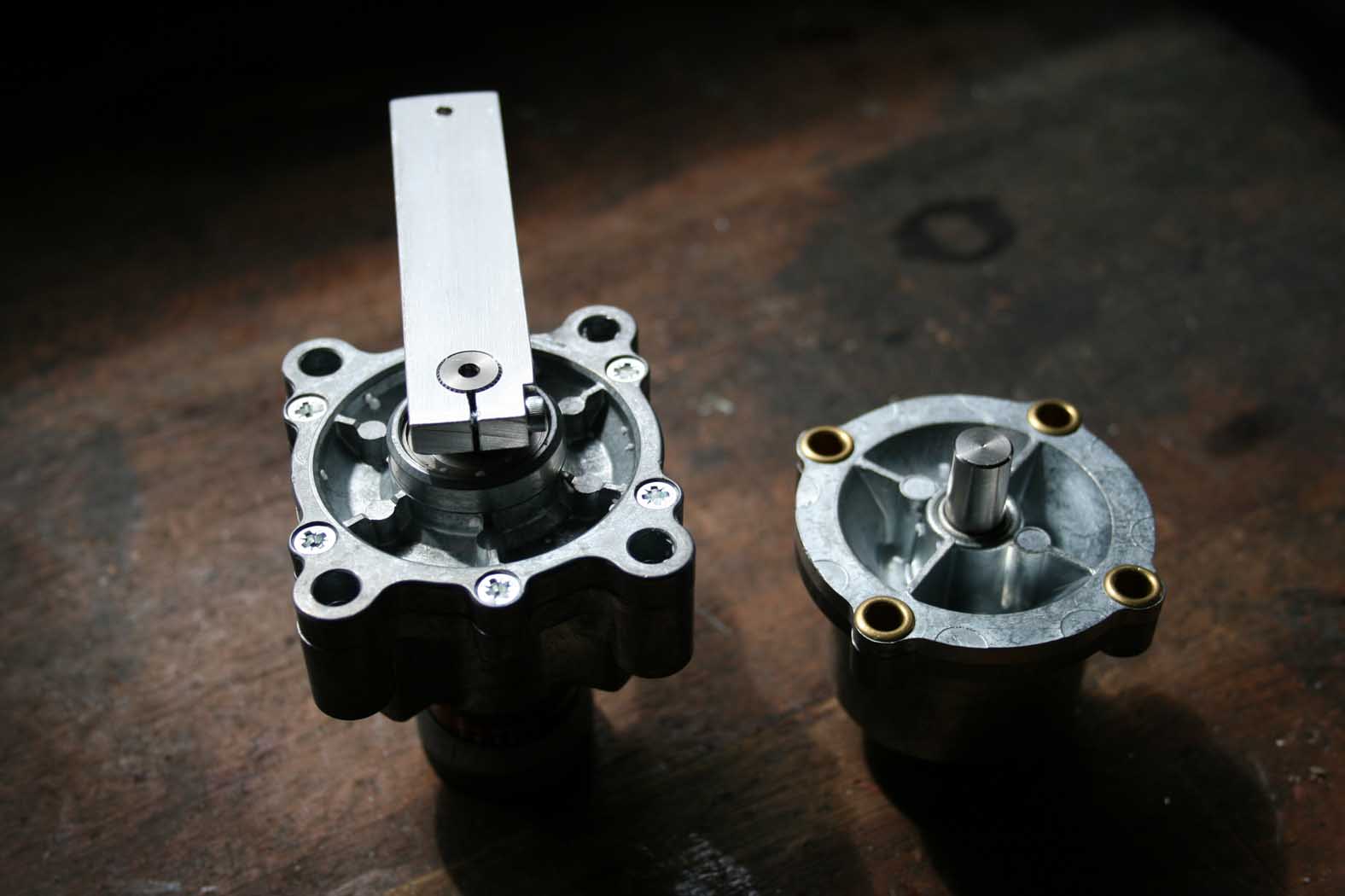
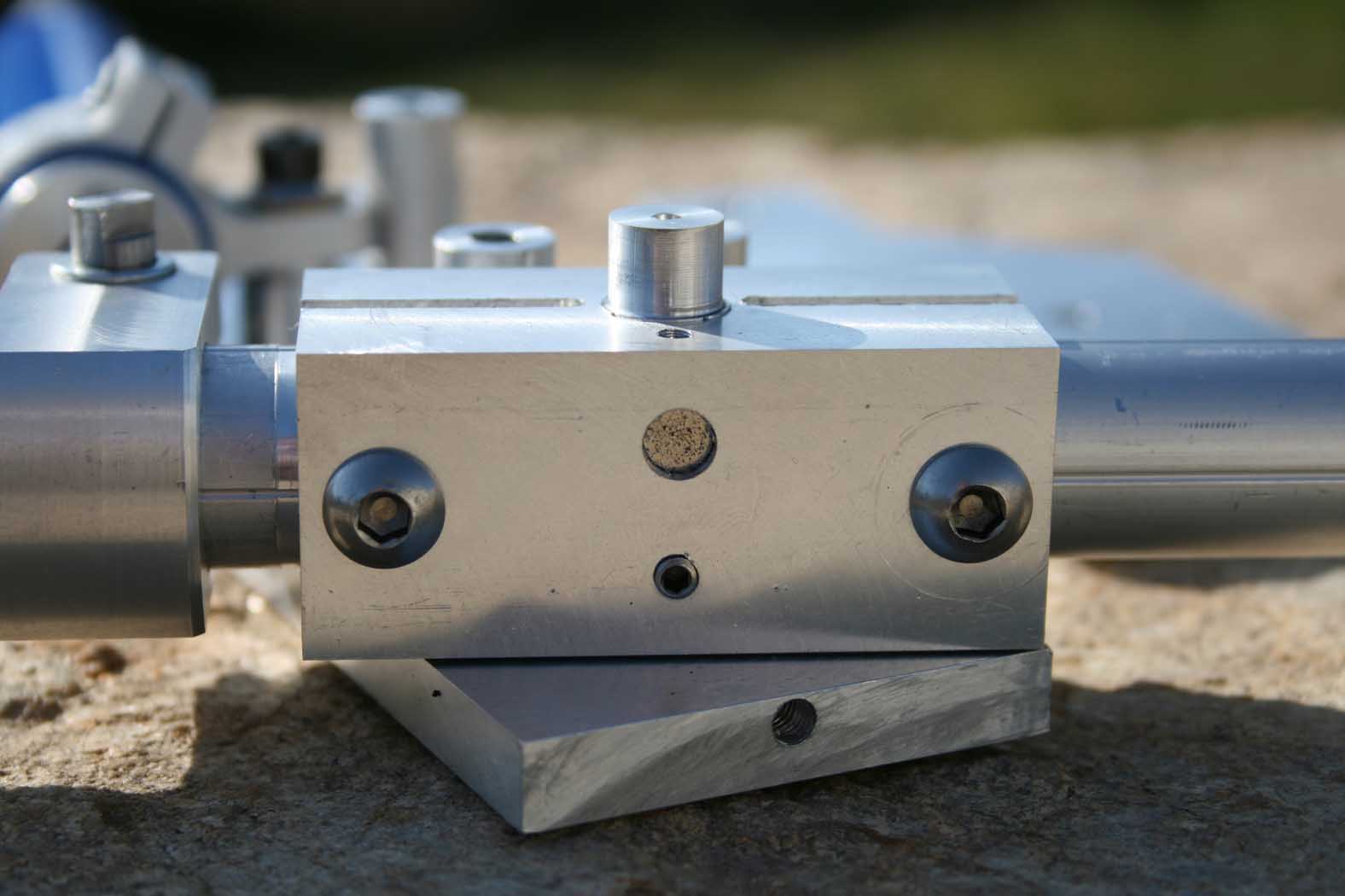
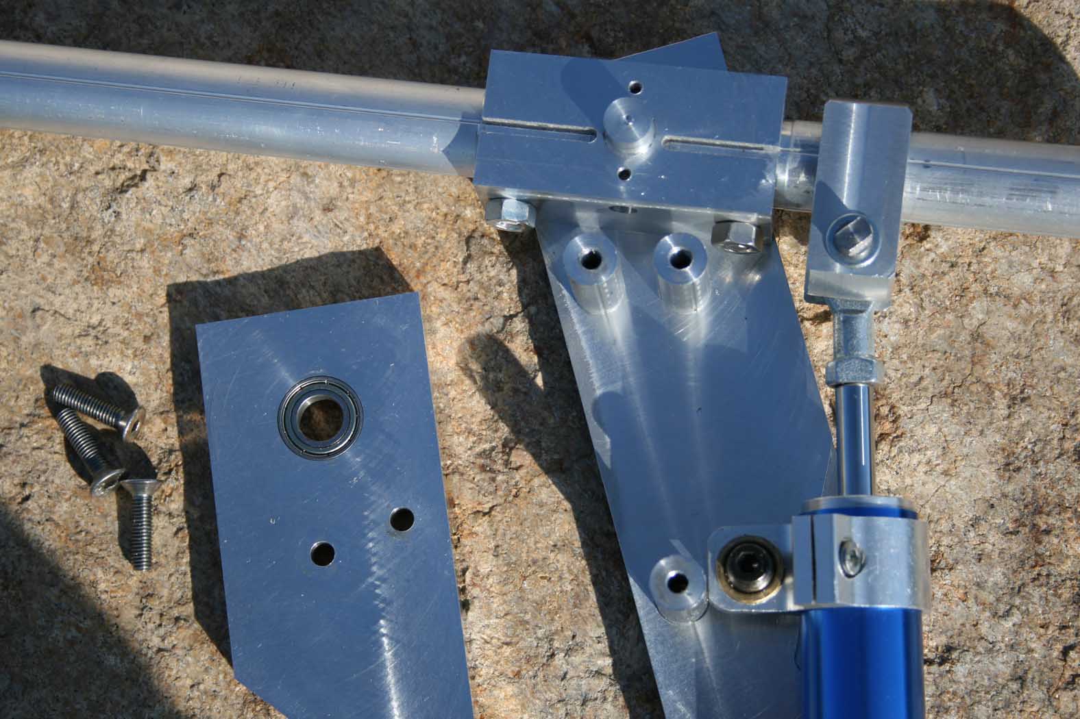
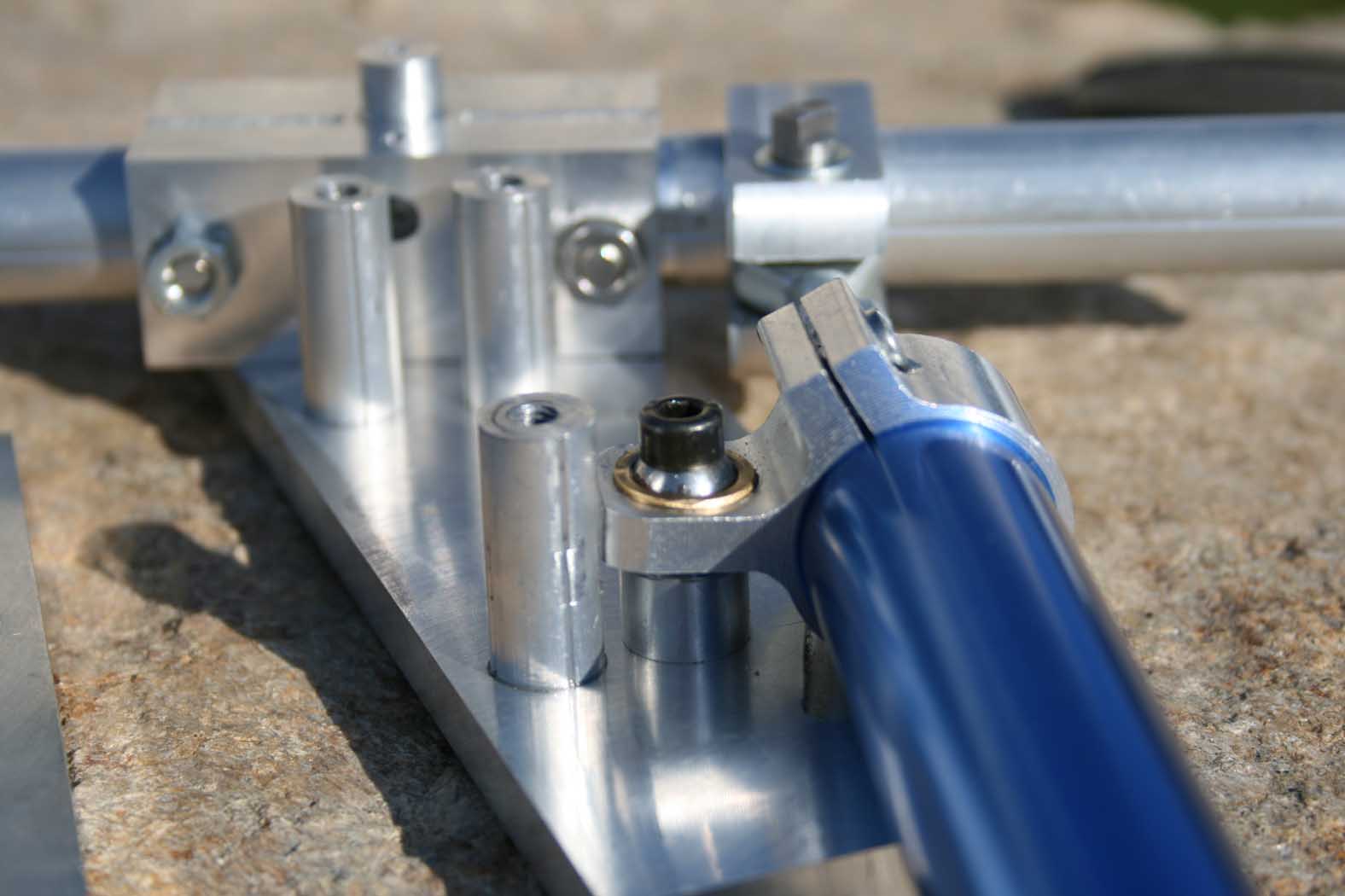
Dashpot benchmarking for a future use in a cougar joystick mode To be in optimum conditions, I dabbled with a joystick axis (depth) - the cougar is just resting on top of the tube to the picture ... The moment arm is 50cm long. (Photo 1 and 2) To avoid damaging the shock (new equipment loan, the damper is fixed between two pieces of wood, the clamp serves as ballast. (Picture 3 +) I benchmark a ajustable vane dashpot and a rotary dashpot. The vane dashpot have a more hard damping than the rotary dashpot. I name the first one "the hard" and second one "the slack". That said, they share certain characteristics while others oppose them. Common features: 1 - When we apply a very very small effort on the lever, you get a very slow movement but it's move !... and more the damping is low (the slack), more it's move quickly with the same force. The resulting weight of the lever positioned horizontally enough to bring it down very very slowly for "the hard", faster for the "the slack" (the lever being 160gr heavy this corresponds to a weight of 80gr placed 50 cm. 2 - Effect of previous point, rapid movement of the handle (like faceted barrels) or the alignment of a target with IL2 is easy with "the salck" (the barrels) and not enough dynamic (IL2) with "the hard". 3 - additional interesting of point 2, the stability contributed by "the hard" will benefit with a KA50 very fickle. Characteristics in opposition: The mechanical principles of these dashpots are different. Reminder: "the hard" operates a displacement of fluid between two chambers (classic depreciation ). "The slack" operates the shear fluid placed between a rotor and a stator (such nesting dolls). Consequently, when you stop pushing on the lever: - "The hard" stops :thumbup: - The soft back slightly backwards. (!) :cry: I think it comes from the plasticity of fluid that generates this rebound effect. Consequence: bad choise for a cyclic always "trim" when you loose the handle . The model Kinetrol X-CRD, and all rotary dashpot that exploit this technology (basically anyone who can rotate 360 ° and more) are not suitable, from my point of view, for a joystick. I've realise a movie of this benchmark (sorry, the comment are in french. I can write a translation of explains if necessary.) For my Cougar mode (cyclic and collective), I ordered last week 2 vane dashpots set slack for the cyclic and 1 set hard for the collective. Tests Kinetrol.zip

-
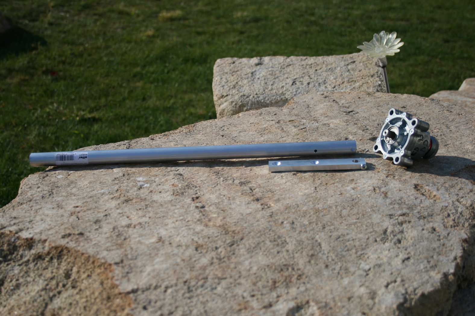
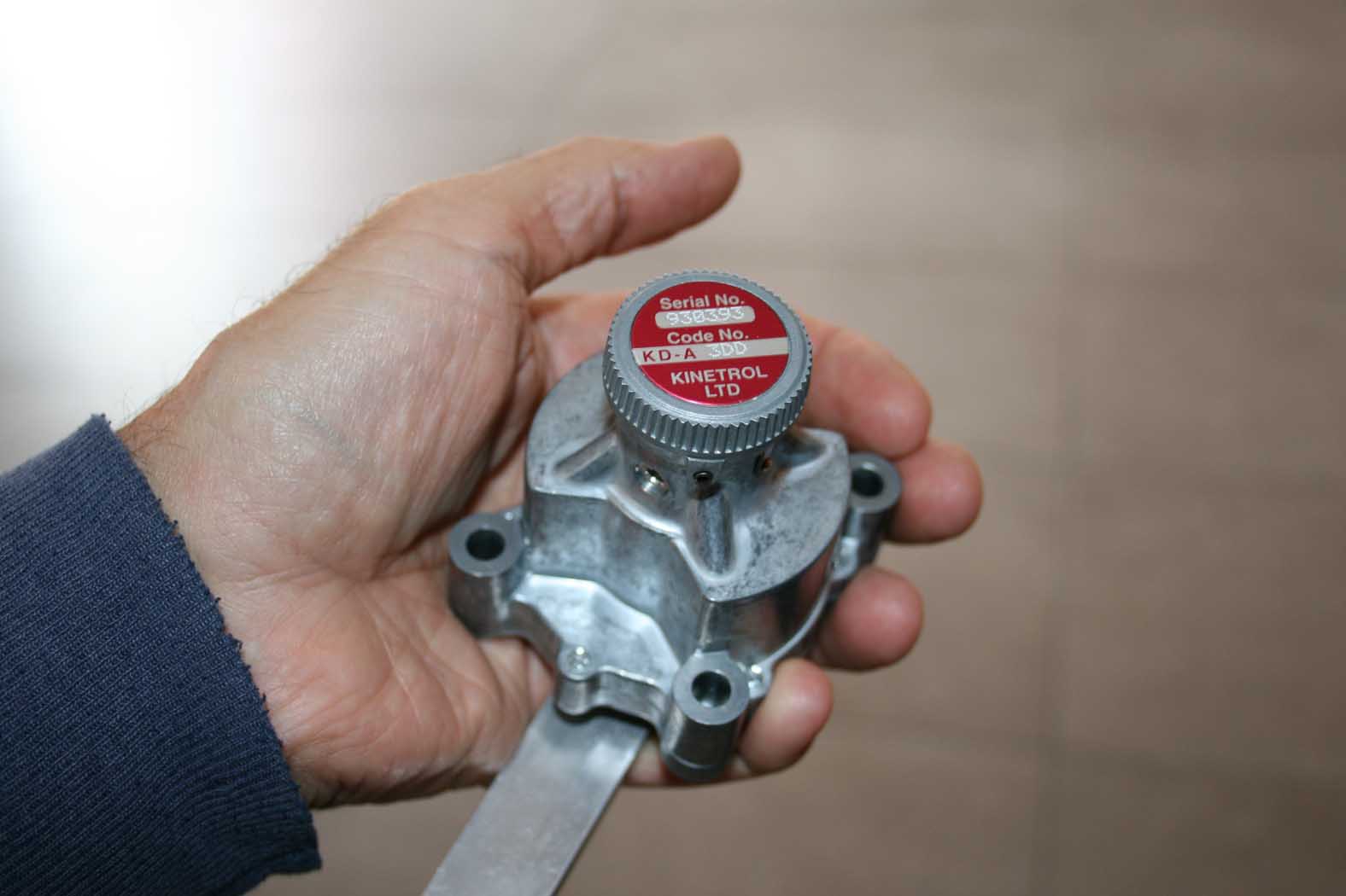
Rotary dashpots benchmark Rotary dashpots are precision fluid damping device witch give a smoth resistance to shaft rotation which increase with angular velocity. I tested two kings of rotary dashpot. Vane dashpot (the device with a dish in alu) give a restricted travel and high damping rate suitable for applications with reciprocating motions. It's a displacement damper. As the vane on the shaft rotates between fixes vanes on the body. Silicon fluid is displaced through controlled clearance from on side of the vane to the other. Continuous rotation dashpot (the little on the picture) gives viscous damping by sharing thin layers of silicon fluid between the concentric surfaces of a rotor and fixed stator. The first picture (in my hand), gives an idea of the size of the vane dashpot(weight 450gr).
-
For my first collective BS, I had kept a pocket bike damper to slow down movements and simulate the effect of inertia and weight as I assume would generate the collective of a true helicopter. The resistance to movements being very strong, I have in first step modify the rank of oil, by successively replacing original oil with oil motor rank 0/40, then some silicone oil rank 100, bike fork rank 5,and vaseline oil). This returned the much more flexible damper, which is what I searched but in put in an obvious place a defect hidden by original hardness. A hard point at the beginning of movement annihilates any feelings, causing one in blow and preventing any fine movement. Besides, some oils are " less fatty than other " (silicone oil) and causes a true blockage, the lip of joints spinnaker not being lubricated enough. I came back in one less thick but fattier oil, motor oil 0/40, and extended the passage of the hydraulic of Dia 2mm in 2.5mm, with for result a net improvement at the same time of the softness of movement (extended passage of oil) and reduction of the phenomenon of blockage, without nevertheless than it disappears. I therefore changed way and got a test under real conditions with dashpots. Suite in a post fellow. Perhaps Oakes, which was source of inspiration for me could add his own comments.
-
My pleasure
-
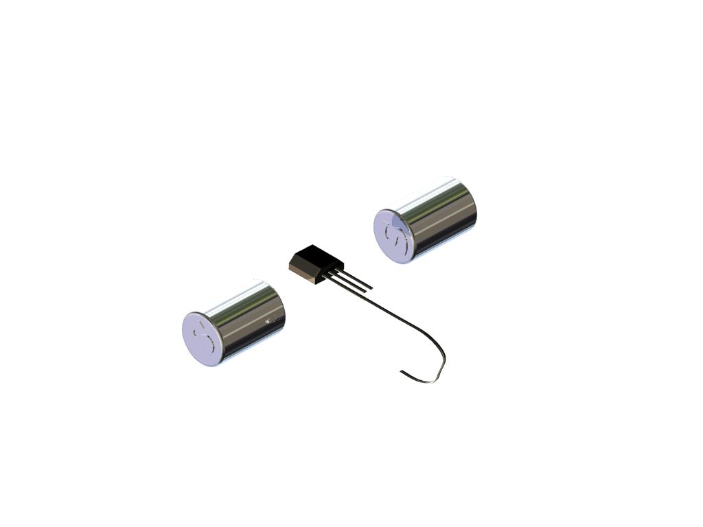
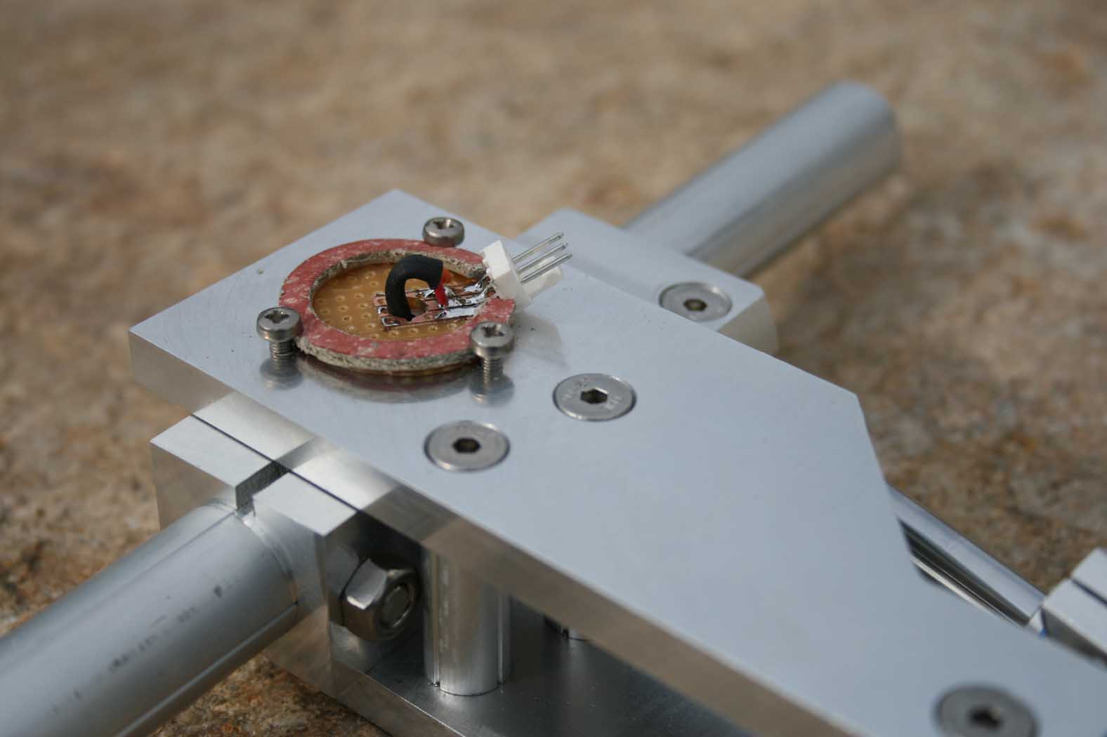
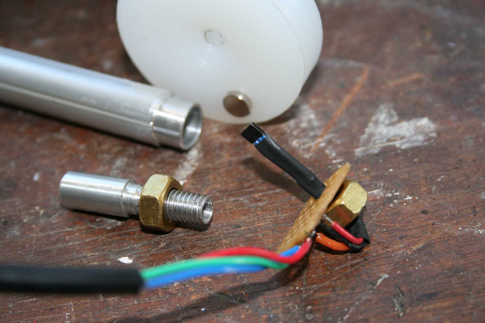
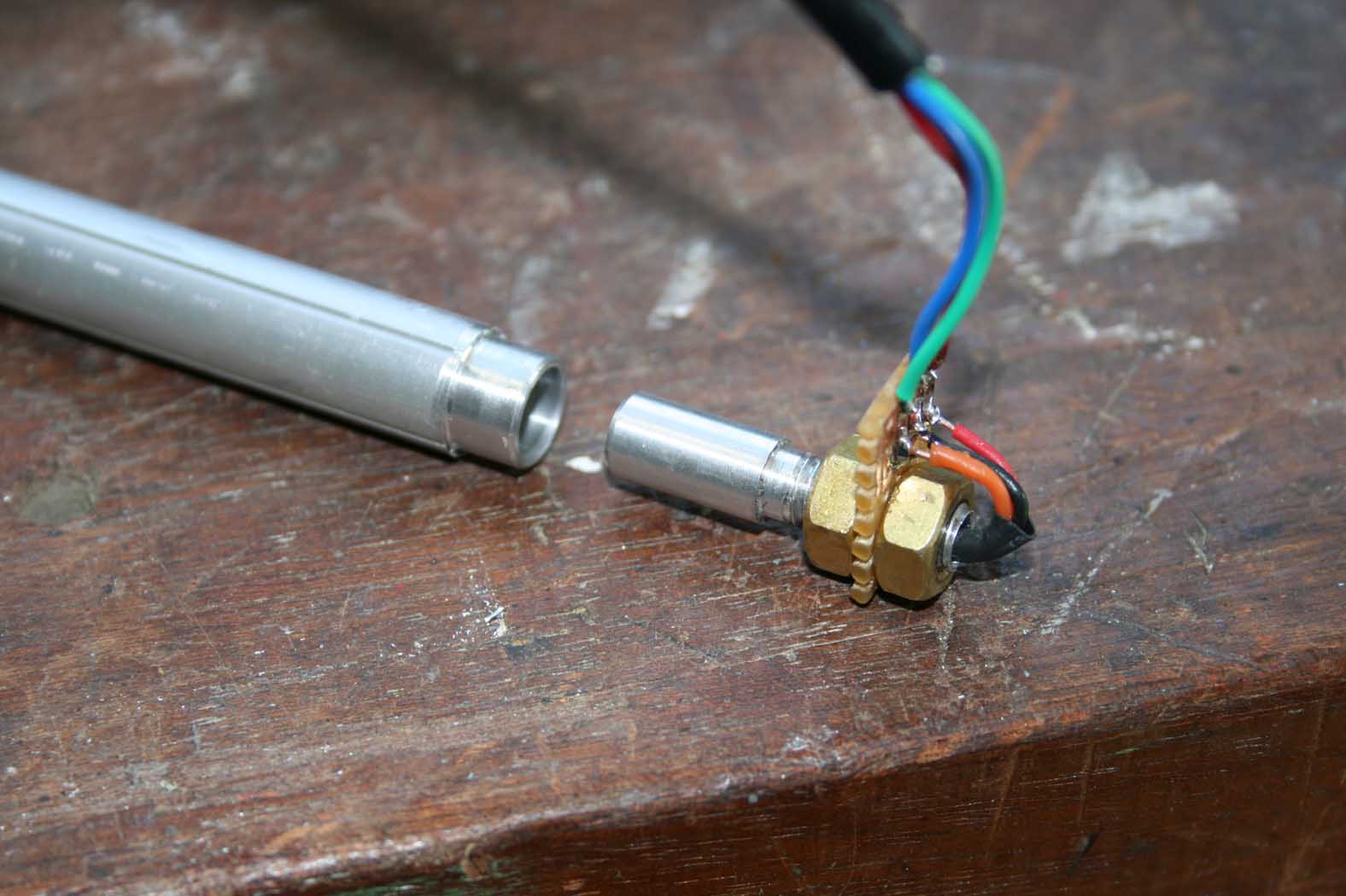
Three first picture for explain the relative position between magnets and sensor. The magnйtique field can move from 0° to 180°. In nominal conditions, 0° = 0vdc, 90°=2.5vdc and 180°=5vdc... Nominal condition=the good magnetic field for the target vdc output on 180° rotation. The good magnetic field depend of force of magnet and gap between the magnet. (you can place magnet(s) in different position of the sensor but my choice if the more easy for tun de output voltage). You can find more documentation on internet (look on honeywell site). From a nominal condition, if you incrase the magnetic field, the range voltage output is produce on a minor rotation (maybe 0 to 5vdc for 60°). I use this principe for tune my mode to have 0.4 to 3.3 vdc wiht 40° rotary for the collective I done. (picture 4 & 5) The last one picture represent how I've install the magnets (with a hole for a screew with block each magnet in the good tuning position). The sensor is install on a pcb fixed on the front plate. The magnets move with the collective. For the tuning, I use a little digital voltmeter, and an old PC power supply. The total cost for 2 magnets and 1 sensor honeiwell SS595A is less than 5Ђ. For the rest, it's an other story... Good luke
-
The manufacturer of rotary dampers that I chose does not come from the motorcycle world but the industry (KINETROL model KAF-DD). I have validated my choice through a benchmark (published on checksix in french) I'll post here as soon as possible. I leave the solution minibike steering damper, because the sensitivity of the current movement is not good
-
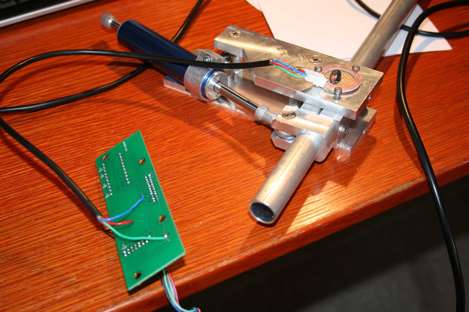
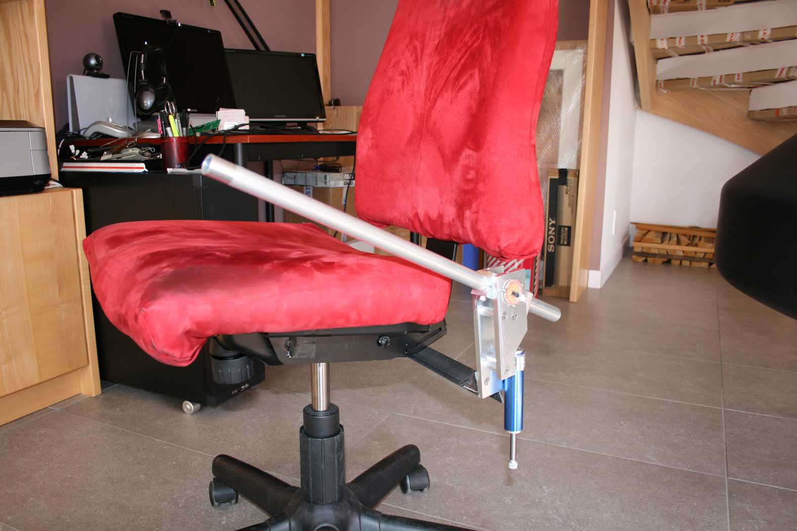
Final assembly of the collective... and the first test online with tha cougar trottle PCB... and the final attachement on my seat.:clap_2:
-
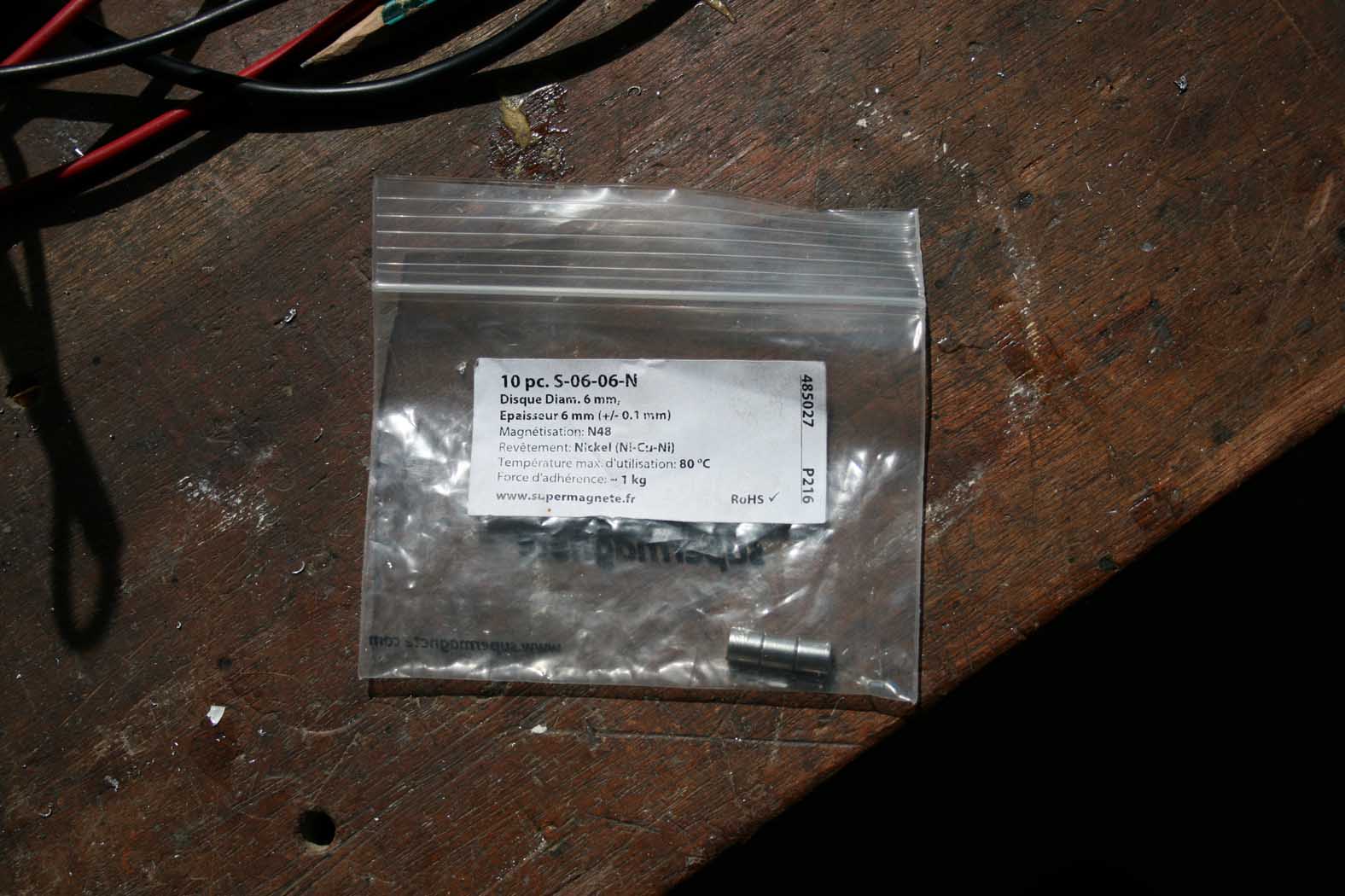
The magnets are sell by <A href="http://[font=Times New Roman" target=_blank>http://www.supermagnete.fr/index.php
-
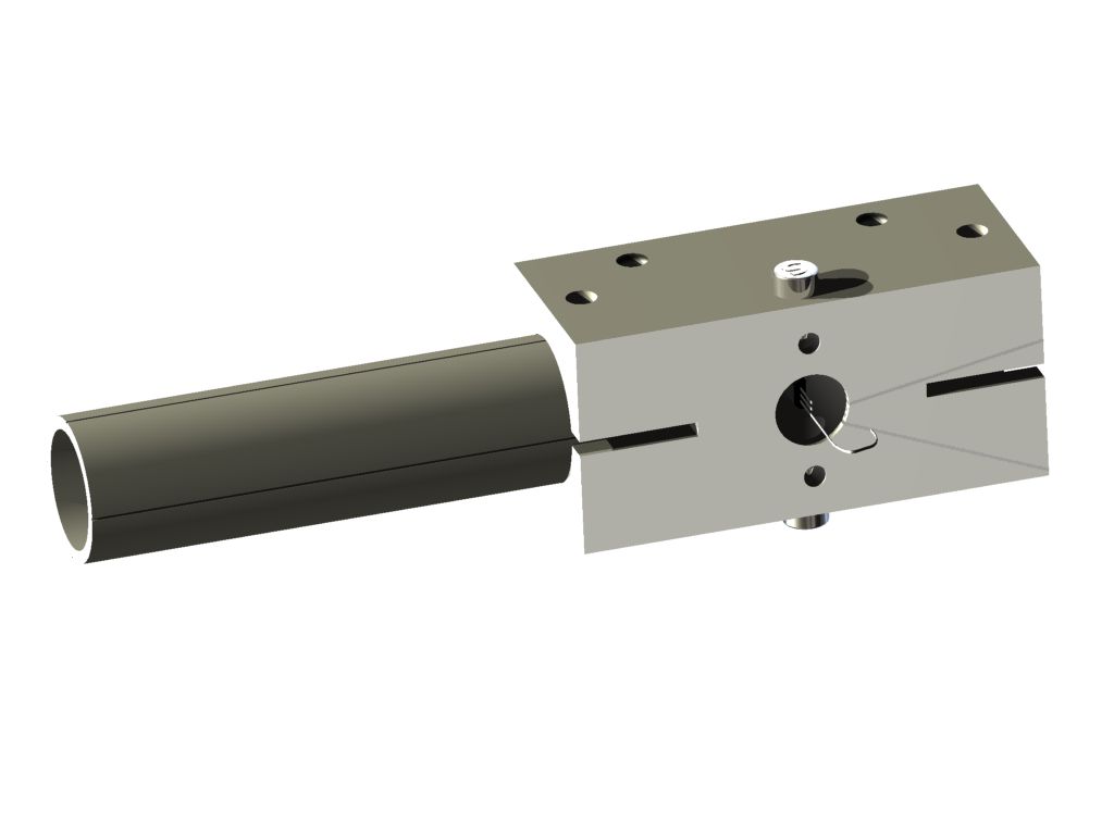
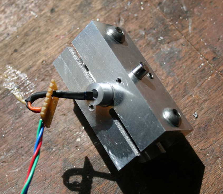
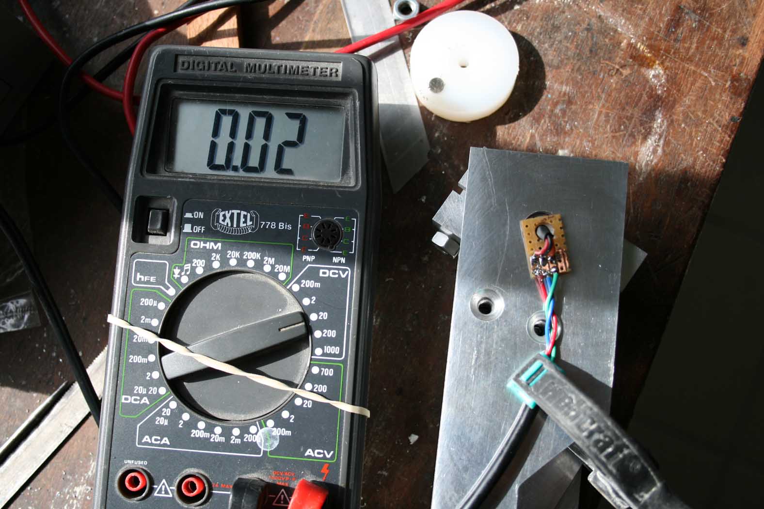
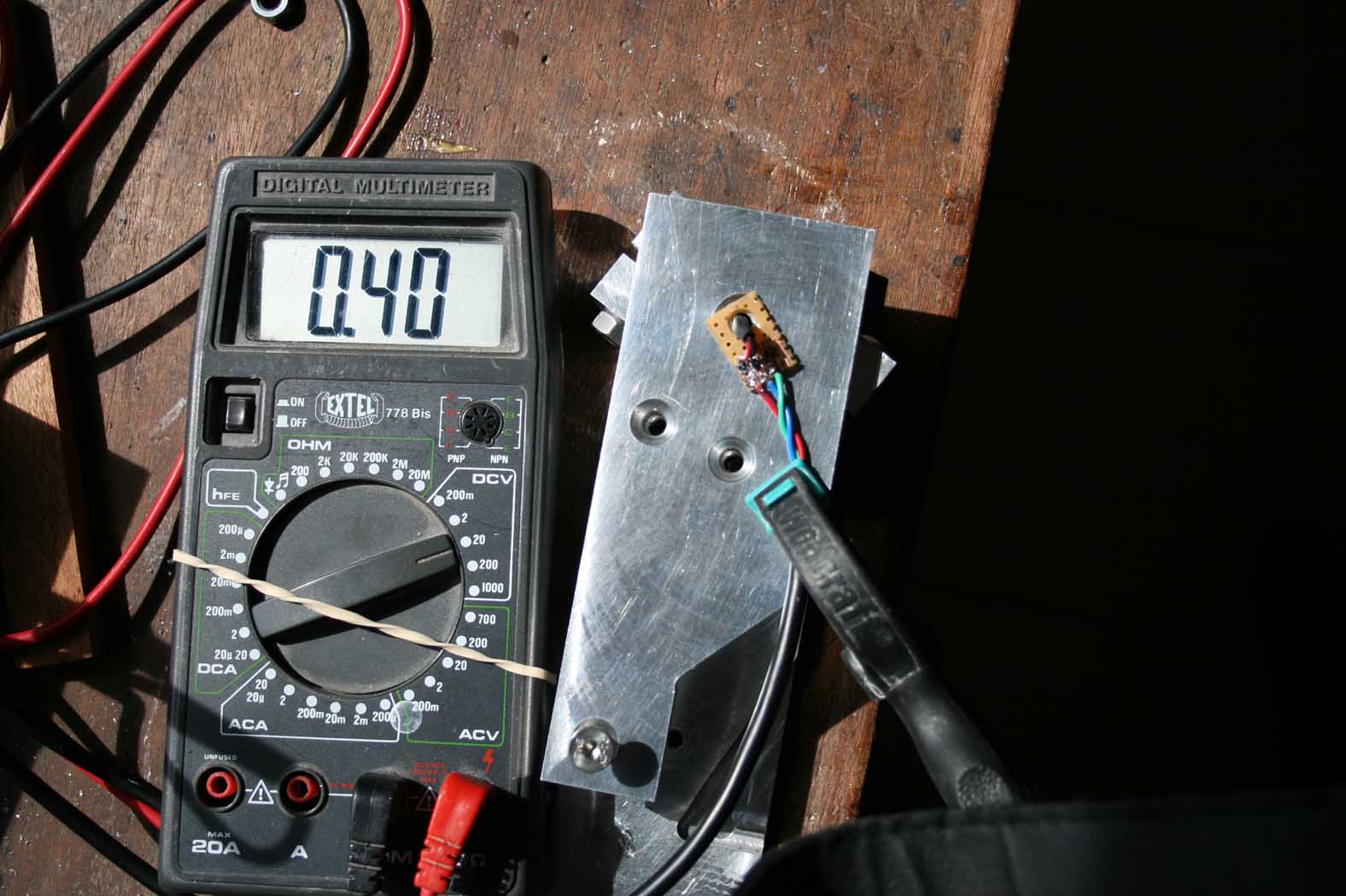
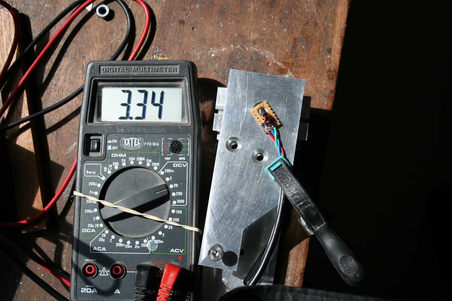
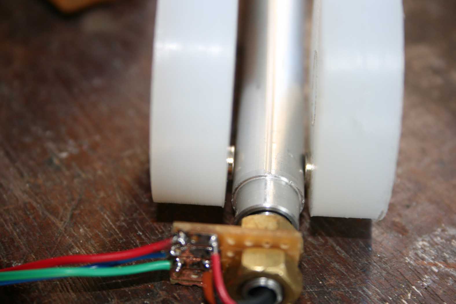
The first picture is the centerpiece of the collective (submitted upstream) where we see the housing magnets on both sides of the axis, the (small) screw for locking the magnets in the set position . The sensor (Honeywell SS495) that fits into a hole in the shaft and is positioned in the middle of the gap magnets. The sensor is fixed, are the magnets that rotate The following pictures show the progress of setting the air gap: e = 4.4mm Voltage = 0.2 => 4.78 vdc e = 9mm Voltage = 0.4 => 3.34 vdc with an angular deviation of about 30 ° The target is reached! remains more than to validate with calibration of cougar ... and the resultant sensitivity (by moving the animal in hand, I can generate voltage variations of 1/100th of a volt.
-
How do I adjust the output voltage of Hall sensor The slope of the curve, then the amplitude of voltage produced depends on the strength of the magnetic field surrounding the sensor Range of Motion The position of the magnetic field from the Hall sensor (symmetrical or more or less eccentric) and power (controlled by the power of the two magnets and thus their distance) to adjust to the nearest target voltage. Screw lock magnets See below (two page in hte show -clic, clic)
-
I'm not able to write directly in english without helper on-line tranlator . :cry: I promise to do an effort to do it and translate my recent expiriment to hydarulique flight control, sites address, budget and plans
-
Uuuuaaaah..! I have started building now..!
loubial replied to Triggerhappy69's topic in Home Cockpits
I have realise a benchmark about different hydraulic solution damper : -classical damper (mini bike steering damper... whith mofifyind the fluid and size off hole inside) - Rotary dashpot - Vane dashpot I relate this bench on a post on checksix forum (in french...) You can read the benchmark on the link below (with google translate...) -
Uuuuaaaah..! I have started building now..!
loubial replied to Triggerhappy69's topic in Home Cockpits
I am stunned by your creativity! On this picture, we can see two parts long and black near the rotary axe. Are they skock absorber (damper) pneumatique actuator ? ....... What are the fonction of that ? -
At this time, I have built the collectif as you can see on this post. I use a pocket bike damper wich is not the best solution. For other command, I'm in prototyping phase You can follow my progrees on this forum http://www.checksix-forums.com/showthread.php?t=159606 When I will be ok, no problem for plans
-
Public. Just ask..and I mail
-
Thank's !
-
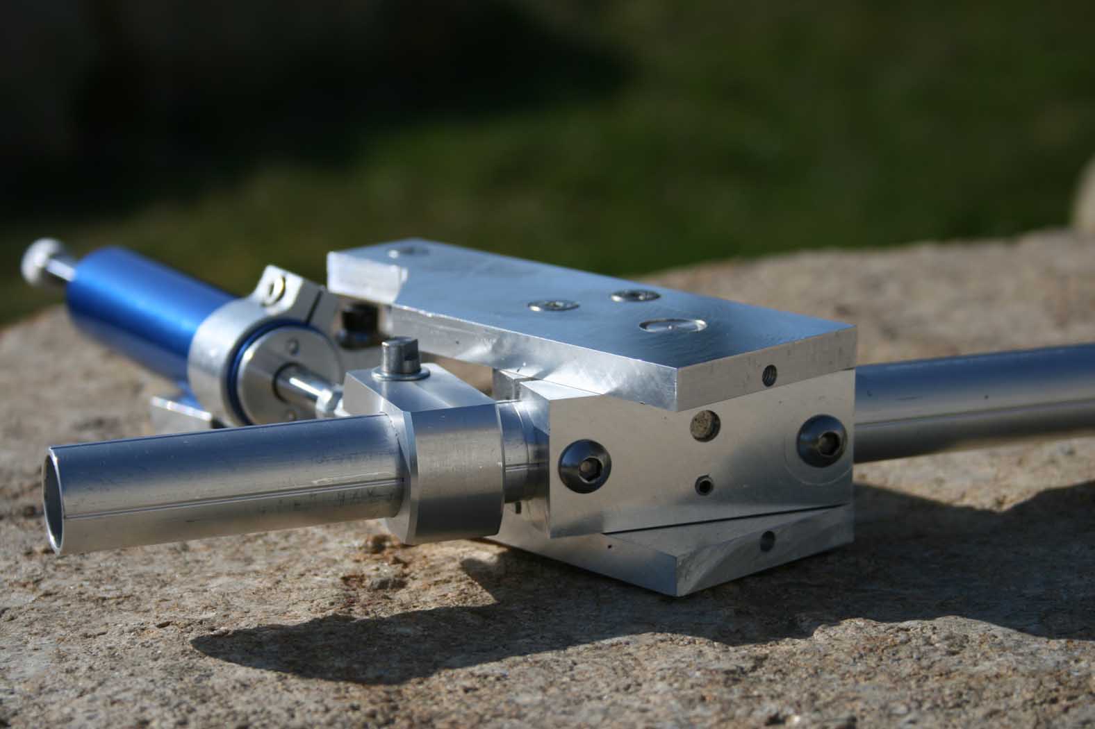
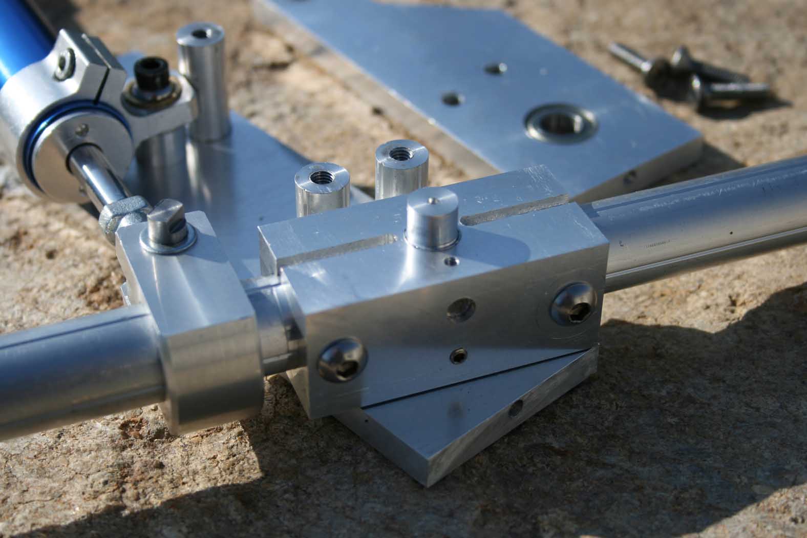
Back in two weeks holidays in the sun ... resumption of the project. The mechanical part is done (excluding the collective head ) See pictures. The small tube is designed to receive a weight-cons if the head is too heavy and unbalanced the sensations provided by the hydraulic jack. The hardness setting is done by adjusting the length of the lever arm (the damper is not adjustable). To give an idea of the size of the part, the damper rod is 21 cm long, the collective arm 40cm, for 30 ° deflection. The sensations are nice. No parasitic friction, no play (although I have to redo the fixing pin jack on the rear tube. The adjustment control trees / bore (without screw assembly and disassembly without extractor) qq hundredths of mm playpurchased through an experience that I have not hardly! (I had to block the punches rolling with screws rather than start over. (It seems that in the automotive industry, the bearings are mounted the glue ...) :cry: sorry for the google translation... I can explain again in a other form if it's not undersanting it remains to implement the hall sensor (connected instead of trottle the cougar) and if my theory is correct ...
-
Uuuuaaaah..! I have started building now..!
loubial replied to Triggerhappy69's topic in Home Cockpits
In fact, I have a secret ... I'm an expert to use ideas from my colleagues :book:... you personally and you do not miss. Your achievements are brilliant ingenuity -
I measure the dc voltage on the pot of the cougar trottle. It is supplied at 3.7 VDC and generates a voltage amplitude of 0.4 to 3.3 VDC on the course. My sensor (ss495A) is powered with 5 VDC, with the idea to generate the same voltage amplitude to benefit from the automatic calibration software. (I understand that modes using a Hall effect lost this feature and I suspect that these modes have amplitudes of tension outside the range of the auto calibration setting cougar (somebody have a feedback?) I made a small experiment designed to approximate the parameters of the voltage amplitude (power of magnets / gap) With a pair of magnet D6mm/L6mm, an air gap and a minimum adjustment range of 180 °, I spend 5.3vcd # 0 vdc that is the nominal voltage of power supply in my old pc. By decrasing the zise of the magnets and playing on the gap, I approach the goal easy 0.4 => 3.3 VDC ... I wil adjust in the final assembly To see the pictures The sensor is inserted into a small aluminum tube fixed to the deck. It is fixed. It is covered by a hollow shaft which supports the bearings. This axis is connected to an aluminum (# 25x25x50) which carries the magnets. All swings around the axis and varies the magnetic field ...
-
Tss tss tss, with a file, a hacksaw, a drill and some bits, you can do the same or almost ready to finish I'm ok to pay the second bottle