Gareth Barry
-
Posts
99 -
Joined
-
Last visited
Content Type
Profiles
Forums
Events
Everything posted by Gareth Barry
-
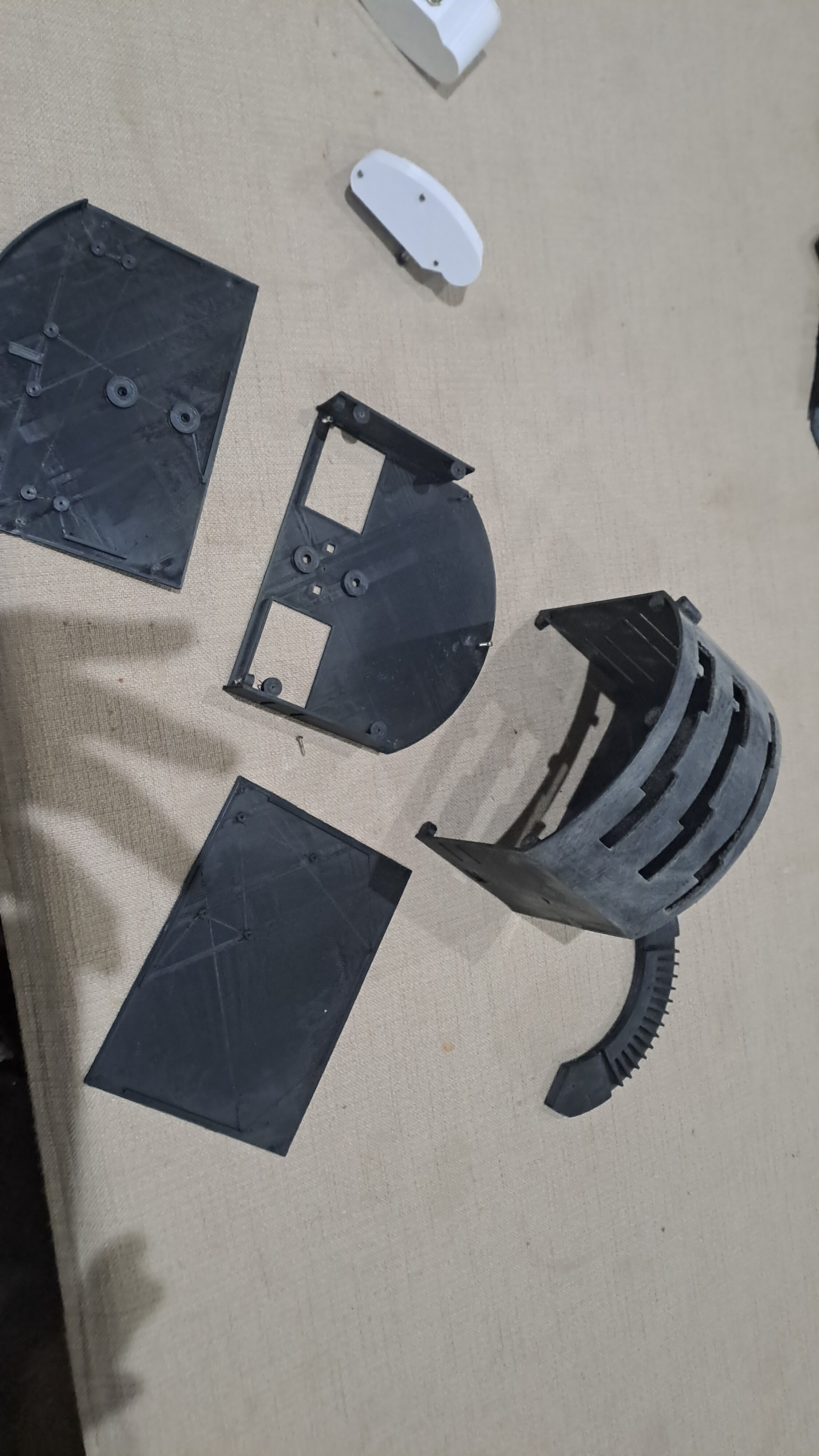
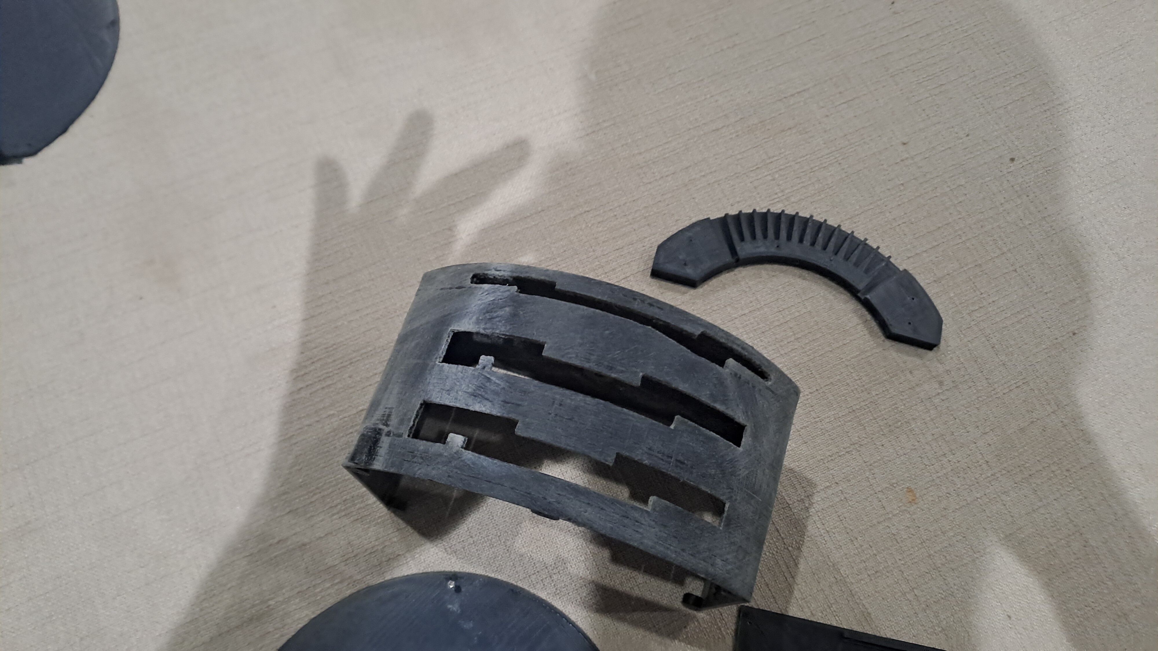
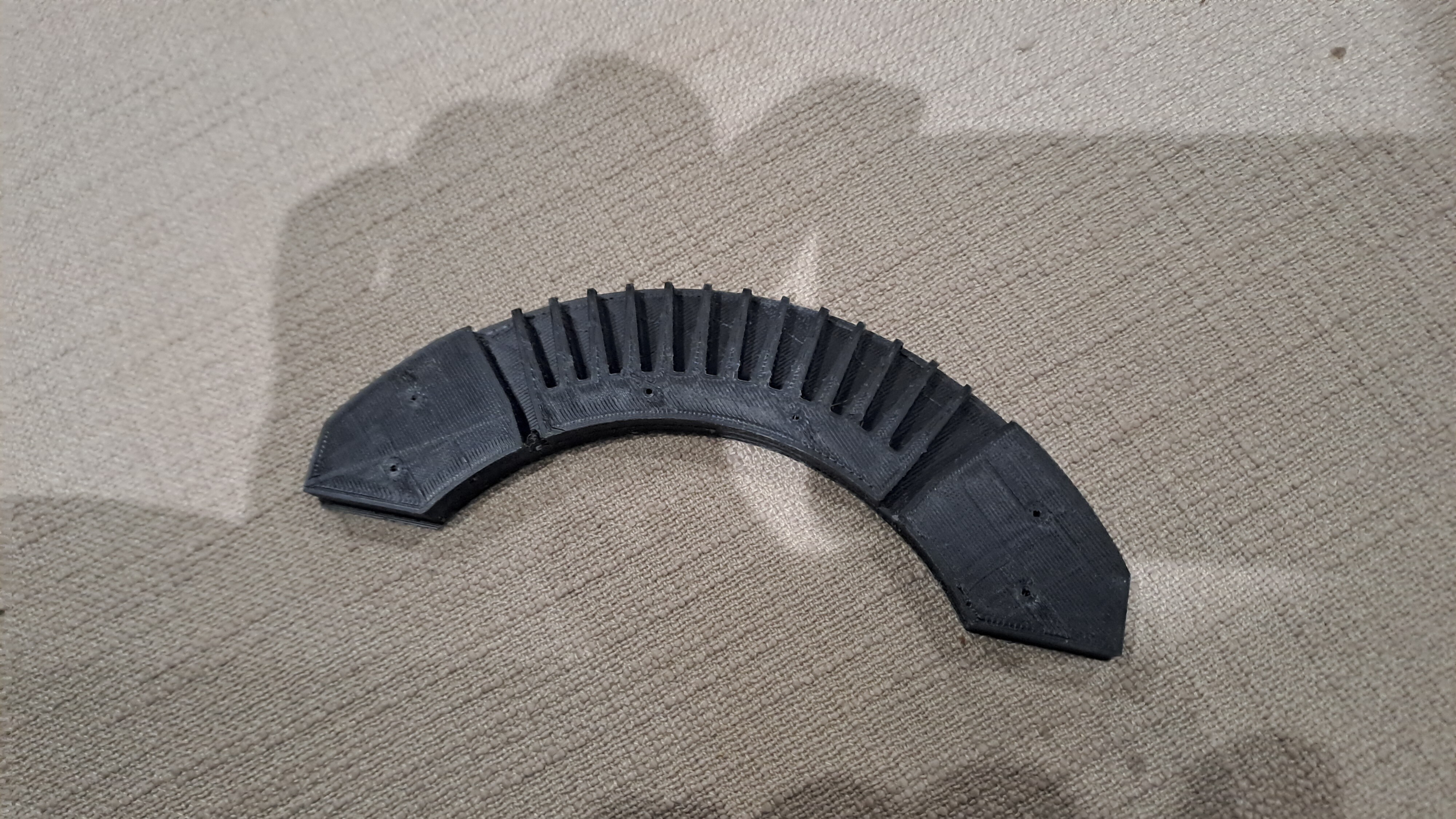
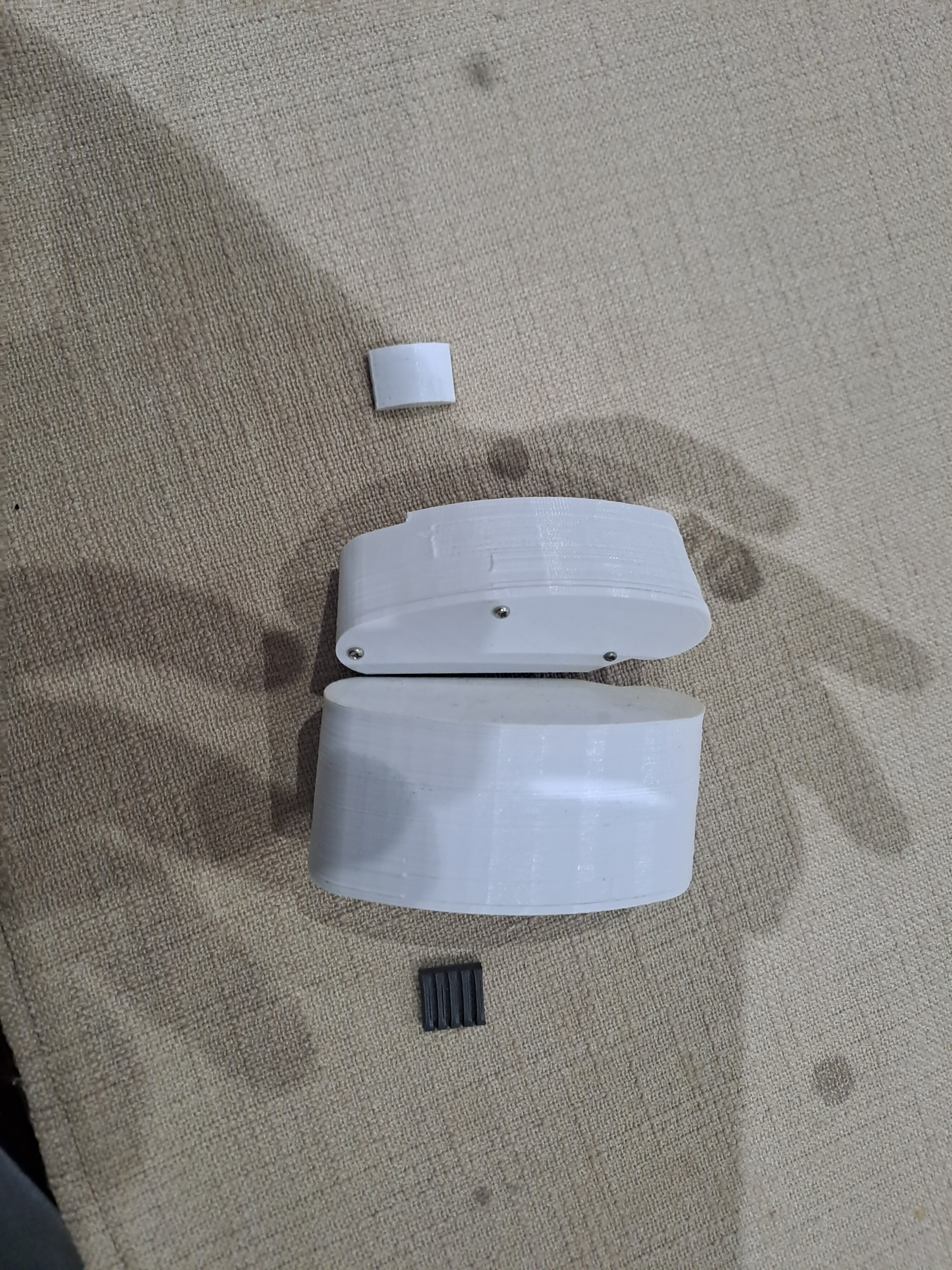
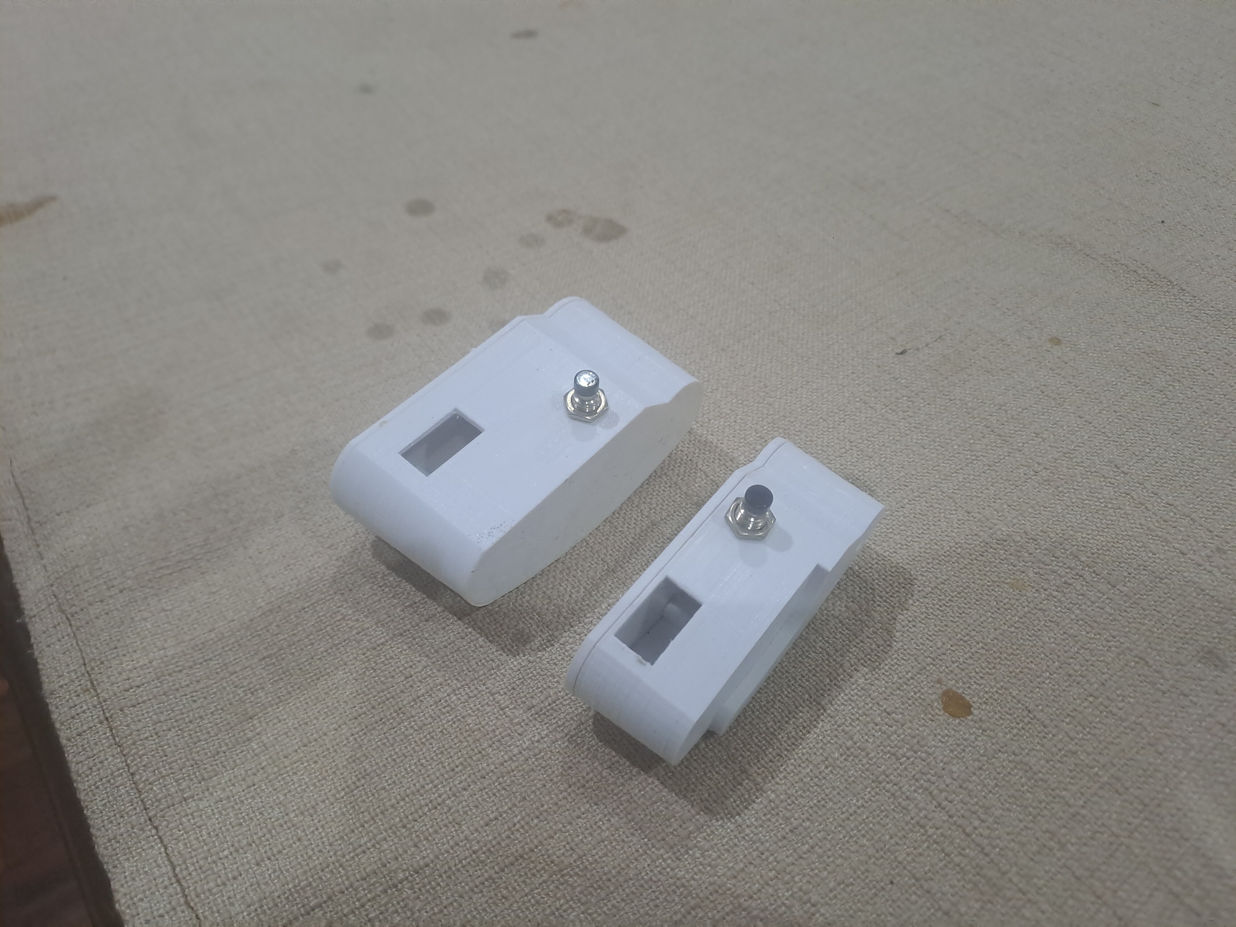
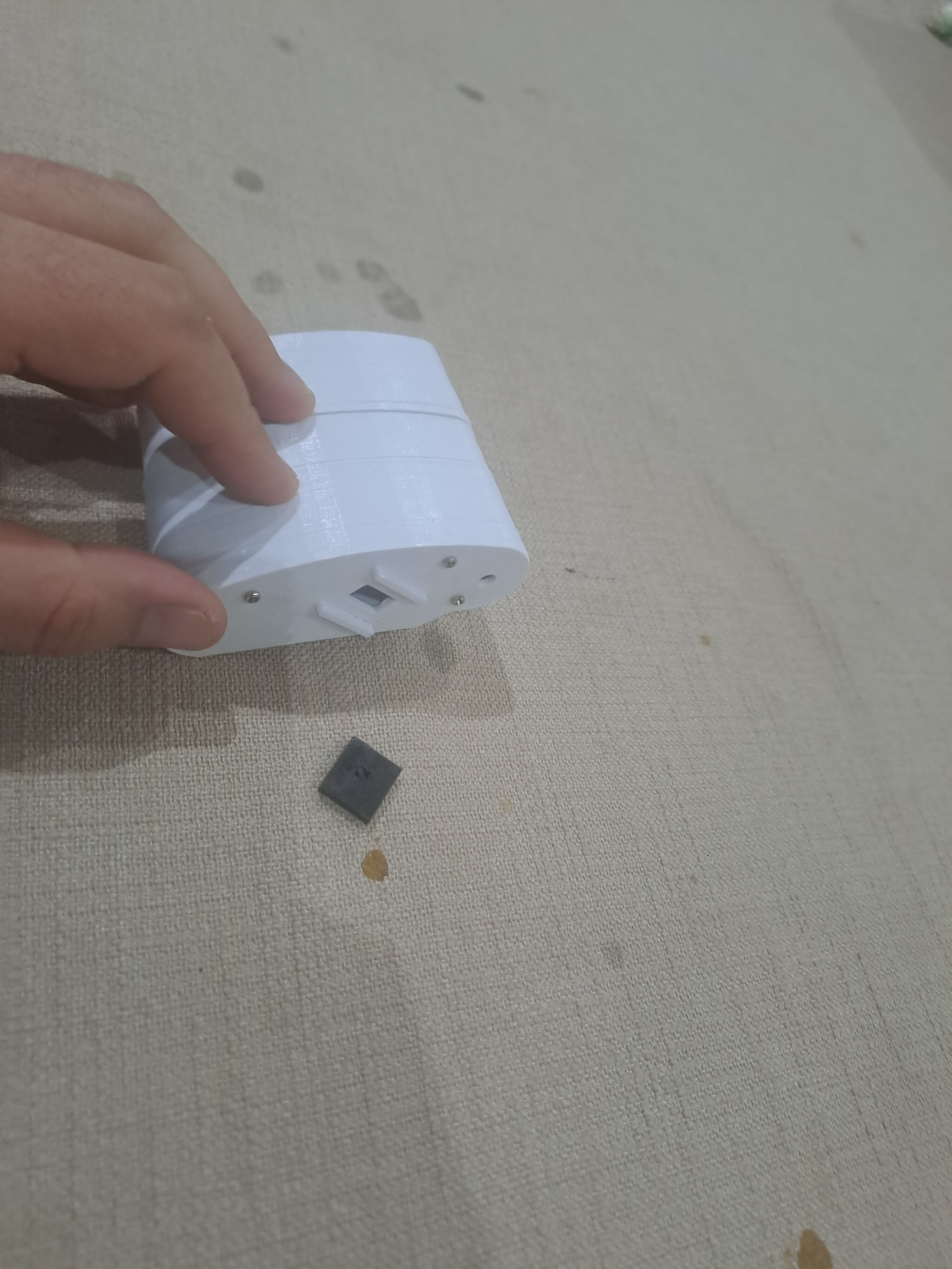
 So, an update for anyone who might still be interested. I have got some of the main parts 3D printed finally. The delay was trying to figure out an efficient way of engraving text in Freecad. In the end I gave up, and might instead laser cut and engrave a sheet of acrylic to act as an overlay. In the end, I will supply all of the raw 3D models so that anyone can make any changes as they see fit. Finally ordered some of the electronics, so will be making some progress in terms of wiring everything up shortly. Still got to finalise the model of the wing sweep handle and print the stalks for the handles. Nevertheless, I can see an end in sight. On one of the pictures, you can see the '4-degree notches' that a spring-loaded protrusion from the wing sweep hand will slot into. You can also see the large slots at the fully forward and overs swept positions to allow the handle to be stowed.
-
Hi all I don't know i this is something that I am doing wrong, but haven't ever noticed before until last night- when I get a PAL lock on a bandit and then fire an aim 7 from about 7 nm, the radar changes lock from the bandit onto the missile itself, causing it to go stupid. This is from a straightforward head-on shot, which previously was a guaranteed kill. Has anyone else noticed this, or is it something I am doing wrong? Thanks
-
OK so, the 3d printed parts have worked well - the laser cut acrylic, not so much, sadly. I was shocked at just how brittle the stuff is, and the laser cutting didn't quite get all the way through the 5mm sheet. I tried to bend the parts out, only to crack through most of the parts at the edges. It looked very pretty before that though! I am probably at this stage going to redesign the main chassis of the throttle to be 3d printable - would probably be easier for most people. Oh well you live, you learn! Still chugging along in this project, hopefully it will be of use to simpit builders.
-
So my plan is, to first build the throttle as a basic axis, without the servo actuated autto-throttle and wing-sweep mechanism, and then try to add in the motors and drive units for those. The whole unit will obviously be built with the accommodation for ser-motors etc in mind. Now, regarding the system to motorise the throttles and wingsweep- I have come up with 2 ideas, and I am unsure as to which is best- I may experiment with both. idea 1 (the one I have done the most planning for) ; is to use moderately geared 6v motors, driving the throttles and wingsweep handle by way of gt2 belts. The 'stalks' of the handles have gears that I have drawn that will accept a 6 mm gt2 belt for a 3d printer. Each handle will have its own hall sensor to monitor position, and use a PID (had to learn what that is) to move control the motor which drives each handle. There would need to be some sort of condition that when met 9from a person shoving on the handle) trips out the PID loop and disengages autothrottle/wingsweep. My one thought was to use a current sensor to register a spike in current due the motor being stalled, and use that to trip out the PID loop. However, I would far rather a clever solution in the code that would take care of this without the use of something like hall current sensors. idea 2; use a clitch servo from DFrobot; DFRobot 2kg Clutch Servo | 300°, 2kg, Integrated Clutch (diyelectronics.co.za) or maybe a lighter one, such as DFRobot 9g Clutch Servo | 180°, 1.2kg, Integrated Clutch (diyelectronics.co.za) This would then drive the handles, which would still have analogue hall-sensors to monitor position regardless of whether the servos are driving them or not. I am unsure which of the two ideas would be simpler, bearing in mind I have still yet to code anything in arduino, and have no idea how DCSbios even works !! But, that is half the reason that I am doing this project, firstly or the challenge, and secondly to learn something. Heck, this project has already taught me what a PID is and how a servo works! As always, I appreciate feedback and thoughts. Rustbelt, here's seriously hoping to hear from you...
-
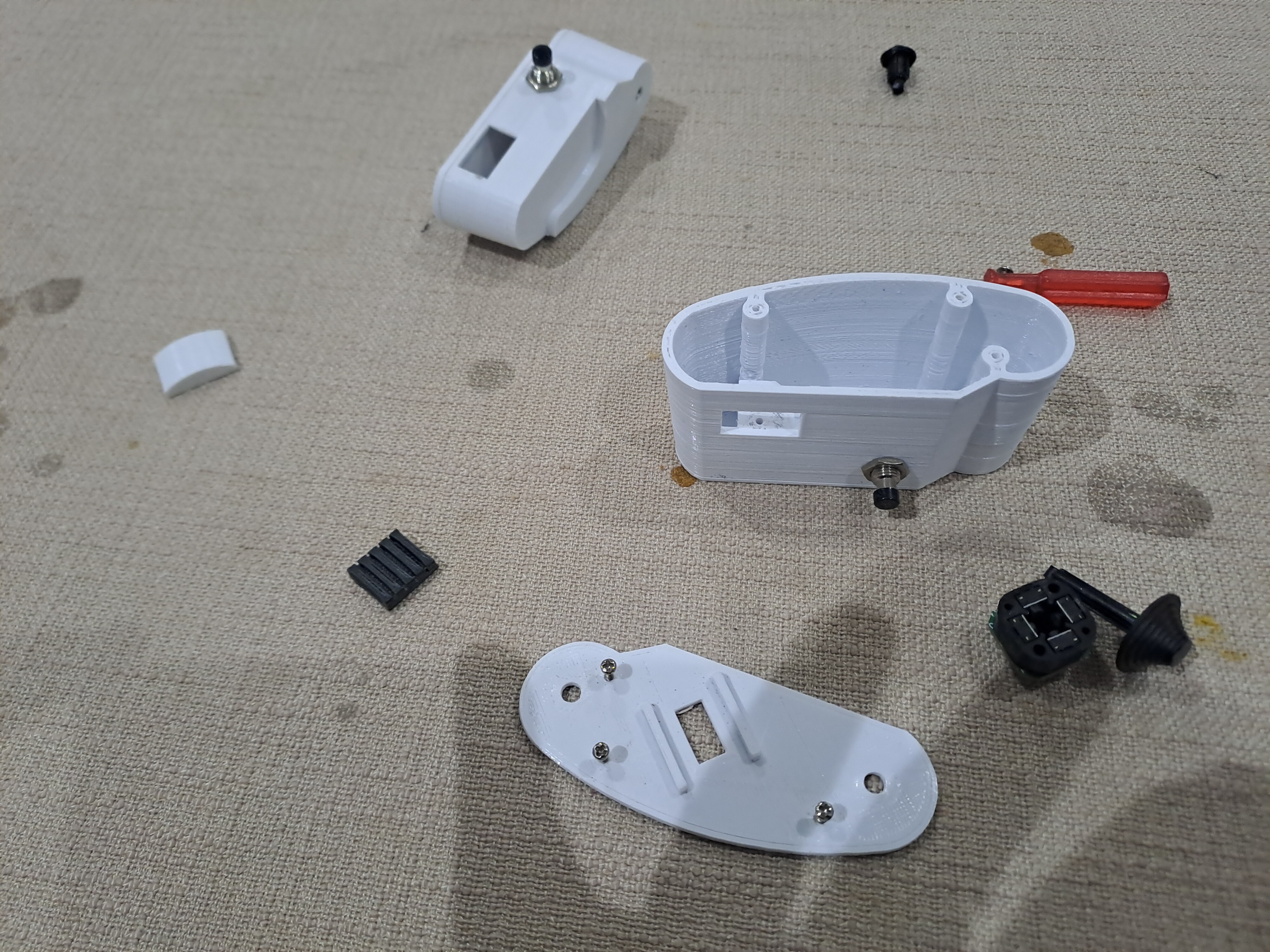
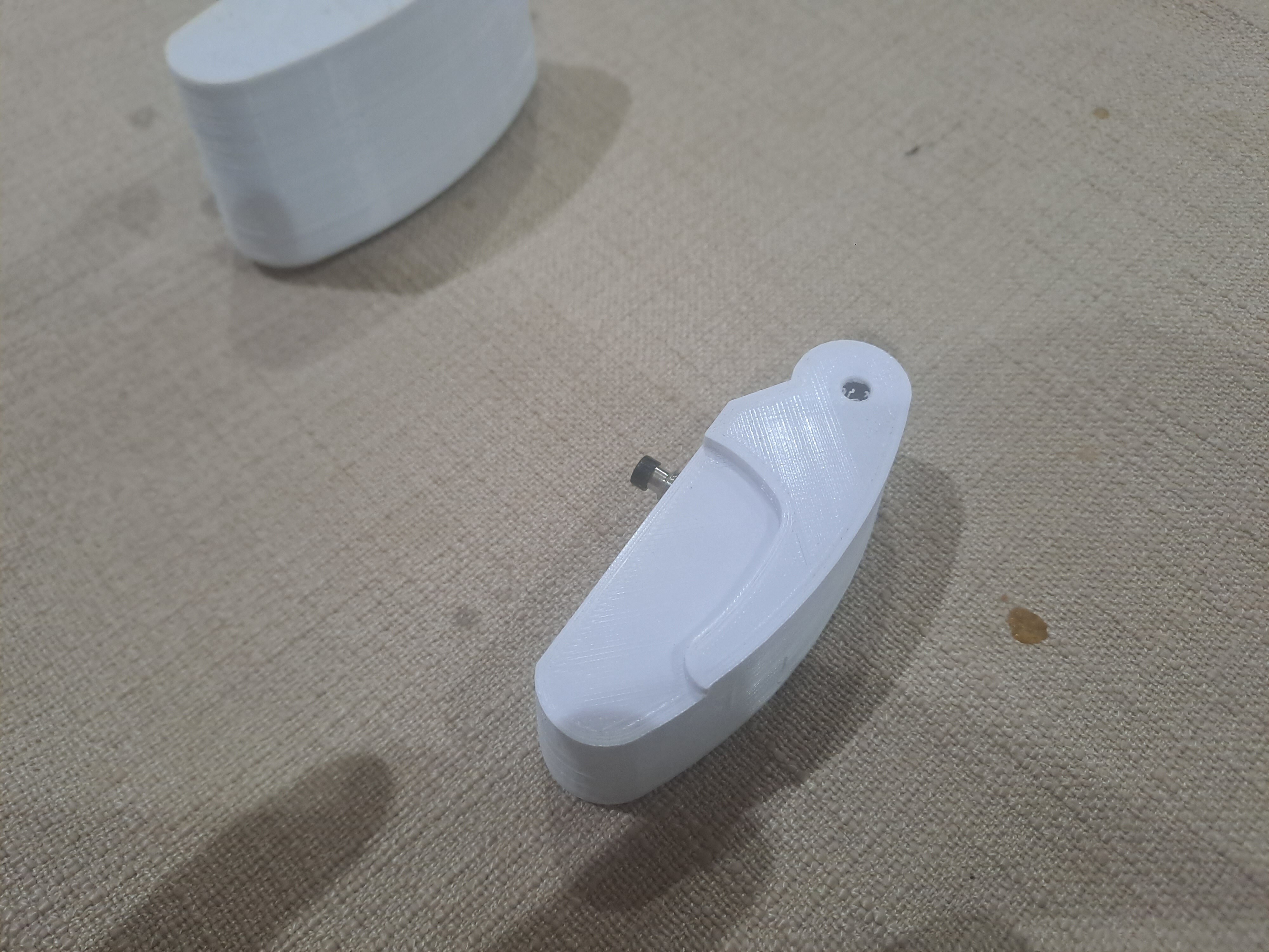
OK so, after a holiday in the UK and the Netherlands....(btw, I HIGHLY recommend the Soesterburg airforce museum in the Netherlands, great value for money, and ticked off many of my aviation bucketlist items to see...) So, have made some progess. Chronocidal, your CAD model looks great - my CAD skills are not nearly as good. However, I may try to implement your design. In the meantime, I have begun 3d printing the throttle handles - pretty happy with how they came out. I will begin wiring the up this weeekend. I haven't included models for the hat switches, as i thought most people would be able to do that themselves? However, I may do that anyway (include them). Already, I am seeing some improvements that could be made to the model, for instance, the holes for both ha-switches should be bigger - I will get onto fixing that. Again, I will provide all of this for free, hoping that someone else will use my models, and perhaps build themselves this throttle. I am also unsure of the size of the flap handle - it seems to scale according to the pictures but it really is small? I bought the black acrylic to begin laser cutting the templates for the throttle body. I ordered 5mm acrylic, which I am now thinking might be overkill- perhaps 3mm would have been a better choice. I don't want to waste the money I spent on the 5mm sheet however, so I will probably go with that for most of the chassis, and just use 3mm for the curved part on the top. All in all, I am happy with the overall shape and fit, especially considering that I am only learning all this stuff.
-
OK so, the summary of what I have done to this point. For the last few days I have been checking and rechecking clearances etc, this is because my CAD skills are limited at best. Still, we do the best we can. Still have to; -engineer the push switch which allows the handle to be stowed, as well as tell DCS that the handle is being stowed -engineer a detent system for the different flap positions, ie up, down, emergency up and emergency down (even though emergency down does nothing as far as I know) -decide on how I am going to mount the magnets for the hall sensors - there will be a few of them -decide on what power supply to use for the motors; at the moment I have drawn a hole for a kettle plug input, which would mean that the 12v DC for the motors would all be done with internal circuitry from a mains supply - I am not sure whether to just go with a generic commonly available 12v input and save myself the bother -decide on either 3d printing the flap lever or laser cutting it from aluminium and then bending it. Other things I should mention; I am thinking of using commonly available gt2 belts that are used in 3d printers for the pulleys between the motors and the levers, however, I may go with gears. I am probably going to make the parts as they are currently drawn, check that they all fit, and then correct as needed. I will update the files with any corrections that I make. My plan is to get it functioning without the motors, ie as just a basic input throttle, and then get the motors working. At the moment, I am getting ready to go on vacation so it probably wont be until mid July that I begin laser cutting and 3d printing parts. At that point, my hope is that I keep receiving suggestions, criticism as far as construction choices are concerned, so as to improve the design. In any case, the CAD files are will be here as at least a starting point for anyone who wants to make something like this. f 14 throttle.zip
-
Chronocidal, that's an excellent illustration, and thank you!! And it looks a lot like the original!
-
Thanks so much Parkerfly, those pictures are quite helpful. I may, or may not, decide to try to model something with the same mechanics. As I said, even if I don't those pictures will be very helpful. At the moment i am leaning towards a simple push-button switch which will let DCS know that the handle is now being pushed in. However, this may change. As I said, getting there. Determined to see this project through, although it may take some time.
-
One other part that is giving me a headache- probably due to my lack of modern manufacturing knowledge - is how to go about making the wingsweep cover. For a once off part for myself, I would probably just hand carve a form out of wood and then vacuum form some clear acrylic over that - but again, I would like this to be reproduceable by anyone else if they so wish to do so. So, can 3D printing produce clear parts? And clear enough to be able to see the wing sweep handle underneath? I have my doubts to be honest. Perhaps the side profile could be laser cut from clear acrylic, and then the curved part bent by hand and then glued to the side profile using MEK solvent? That's about the best that I can come up with.
-
Thanks Parkerfly, it's good to know I'm not the only one crazy enough to want to want an f-14 throttle! Making steady progress on the CADs. However, I have run into something of a dead end in terms of the mechanism of the wing sweep handle. Not so much in terms of the pulling it out of spider detent, as well as the 4 degree notches when in manual - I think I have come up with something that models that. I am trying to model the functioning of the actual yellow handle on the end of the wing sweep handle. Specifically, there is a button on the yellow handle itself which must be pressed to allow the handle to be stowed away. I have no idea how this actual mechanism works. Now, I could design a system that achieves the same thing, and I have tried to make the parts look as authentic as possible - but the way the mechanisms work is not exactly the same. Bare in mind that I want this whole thing to be achievable by someone with access to a laser cutter, 3D printer and not much else in terms of manufacturing - no welding, cnc milling or anything like that. So, if anyone knows how this part works (the handle itself with the button) please chime in...
-
Thanks Rustbelt - also for your response in the PM I sent you. I am seeing that the electromagnet solution that I had in order to act as a clutch so as not to strip the gears or burn the armature of the servo is unnecessary. I think I am going to go with a current-load sensor on the servo, and when that exceeds a high value from being stalled due the pilot shoving on the handle, the arduino will switch off the servo motor, simple.
-
Sooooo.... For anyone who is still interested in this, I am posting some of the files of my 3d drawings, the flap handle, as well as both throttle halves. Still thinking about how to implement the autothrottle and the motorised wing sweep with manual override. In another thread, I discussed some ideas about to implement an autothrottle that can easily be disabled/overridden by applying some force to the handle- and was given the excellent suggestion of using a motorised linear potentiometer as used in high-end digital mixing desks. So then i got to looking at how these motorised linear potentiometers work (ALPS seems to be the common brand) - and it seems to be a simple belt pulley round the motor when then moves the position of the wiper - there don't actually seem to be any complex clutch systems or anything at all between the motor and the potentiometer - I am guessing slipping of the belt is the extent to which there is any clutch mechanism. With that being the case, I am in two minds as to whether to just use a motor with a belt and pulley to move both throttles and the wingsweep handle, with hall sensors on each of the latter so as to measure position, or to buy motorised linear potentiometers and use those. In any case, the 4 degree 'notches' can be quite well simulated in that case, by coding the motor to try to 'restore' the position of the wiper to either the 20 degree, 24 degree, 28 degree position etc etc. This seems on the whole to match what Rustbelt was suggesting, ie to use motorised potentiometers and clever coding to mimick the system as much as possible. In any case, here are the files of some of the stuff I have drawn. f 14 grip lhs cover.FCStd f 14 grip lhs.FCStd f 14 grip rhs cover.FCStd f 14 grip rhs.FCStd f 14 throttle flaps handle.FCStd
-
Whilst I'm at it, let me also mention that the autothrottle function I am keen to do similarly, ie with electromagnets to act as a simple 'clutch' between the servo and the handle. The throttle stalks will have hinges to allow sideways rotation, so that they can be moved sideways through the various 'gates'.
-
Hi Rustbelt What you described is basically how I imagined it (the real system) would work. I have been mulling this over, and I THINK I have come up with something that is acceptable. My goal is not to reproduce the system exactly, as in, the exact amount of force required to 'break' the link between the servo and the handle etc. At some point, some compromises have to be made I think. I am progressing on the drawings and 3D models and I think I am getting to the point where I can post something for everyone to comment on, criticise and hopefully improve. Anyways, here's what I have come up with. The handle will have another lever to the inside of it, which will be operated by a servo, controlled by DCS bios. On the lever will be an electromagnet, which can be switched on or off. On the handle itself will be a strip of steel for the magnet to grip on to (most all the parts will be laser cut acrylic and 3D printed.) Both the servo actuated lever and the handle will have hall sensors to measure rotation angle. When the pilot shoves on the handle, forcing a misalignment between the handle and the servo actuated lever, a few things will happen; i. the electromagnet will power down ii. the arduino will send a message to the PC that the system has now switched to 'emergency wing sweep.' iii. the arduino will now send the position of the handle to the PC. electromagnets for arduinos are cheap and readily available. Also, the '4 degree locks' will be a series of teeth, almost like a section of a gear, scaled such that the notches are in even increments from '20 degrees' to '68 degrees' and then 'oversweep.' The handle will be spring loaded to the 'down' position. When it is pulled up, a spring-loaded catch will flick out, over and ultimately into the 'notches' mentioned above. In order to move from one 'notch' to the next '4-degree notch', the handle will have to be pulled out/up some further distance. Pulling the handle up such that that the spring-loaded catch is now engaged with the '4-degree' teeth, a microswitch will trip so that the arduino knows that handle is engaged with the notches. The notches at the 'oversweep' and '20 degree' position will be somewhat thinner than the rest. When the pilot wants to put the system back into auto, he will push a button on the handle which will retract the spring-loaded catch sufficiently to clear either of these two settings, but not enough to clear any of the others. With the spring- loaded catch retracted and the handle at either the 20-degree or oversweep position, the handle can be pushed down so that the spring loaded catch is now underneath the notches. Pressing 'master reset' will then command the arduino to move the servo operated lever to match the position of the handle, as well as re-energise the electromagnet. When the readings of both hall sensors are aligned, the system is back in 'auto.' Wow...that was a long description!! Congratulations to anyone who read through that, but honestly, writing it all out help me to organise my thoughts on this.
-
sLYFa - thanks so much - it turns out I was wrong after going through your recommended reading.... I would suggest Heatblur perhaps update their manual as imho it's description of the mechanism doesn't seem quite right - maybe I was just misreading it. It turns out that the wing can only be returned to the stowed position in the 20 degree and oversweep. The handle is spring loaded toward the stowed position, but requires depressing the release button on the inboard side of the lever to return it to the stowed position. Interesting..got some thinking to do...
-
thanks Draconus Hmmm...sLYFa, reading through the manual seems to suggest I was right regarding being able to put the handle back into the spider detent at any wing sweep position , although with my ADD and general low IQ I could be wrong? From the manual 'To return to the normal mode of operation, the handle should be pushed into the desired position and pressed down and the guard closed. The MASTER RESET button on the fuel management panel should then be depressed and the wing-sweep system set to the same position as the handle. The servo will then drive to the commanded position and re-engage the handle to the spider detent, resuming normal operation.' I could be reading this wrong? Personally, i have never found the need to open/close the cover mid-flight, so perhaps the procedure of re-engaging the spider detent was specific to the commonly encountered time when this is done, ie before take-off, when then 'desired position' will obviously be full forward sweep? Draconus, are you saying that opening the hatch, then moving the handle without extending it will also disengage the spider detent and let the wing sweep angle be manually moved- ie that extending the handle itself only serves the purpose of providing extra leverage? If this is the case, it would require some sort of clutch system similar to what I am imagining for both throttle levers, such that the pilot can override the servo without stripping any gears. Also, with the handle out of spider detent, does the spider detent continue to move, controlled by the CADC? Or is the servo that actuates the spider detent thingy also disengaged at some point in all of this? I am guessing the latter? Just got a bit more drawing to do and then will show all, for anyone's input and criticism. Thanks so much guys. sLYFa gosh, the 4 degree thing is another complication....I can see why none of the manufacturers have given this thing a go... So does that this mean that in emergency mode, only discrete values of wing sweep are selectable, in increments of 4 degrees? Thanks again
-
Ahh Ok thanks. Hmmm, gonna require some thought as to how to engineer a system that imitates this, but your post is very helpful. At the moment i am thinking of 2 'axes' that lock into each other, one for the 'spider detent' and one for the wing sweep handle.
-
Greetings all. So I have been slowly making progress in designing a full throttle for the f 14. The throttleteck version is a bit pricey for what it is imho, and has certain limitations. My plan is to implement a functioning, servo actuated autothrottle and wing sweep handle, which will talk to the PC via DCS Bios. I also intend to make all of the plans etc freely available so that whoever else is crazy enough to make their own f 14 throttle can do so. My current question is regarding the 'spider-detent' of the wing sweep handle actuator. My understanding is that there is essentially a 'pin' on the handle that fits into a 'slot' on the actuator, such that when the pilot pulls out/up the wing sweep handle, the handle itself is disengaged from the actuator and is then free to move. The wing sweep position will then be determined by the position of the handle, and not the CADC. However, the CADC will still move the actuator, thus for the pilot to put the system back into auto he/she must first move the handle to match the position of the 'slot' in the actuator (ie the spider detent) and then push the handle back down into it. At this point, the wing sweep handle will then obviously move with the actuator. Have I got this right? If my understanding is incorrect, please correct me, so that I avoid going down the wrong path in designing a system that imitates this. Thanks so much. Regards Gareth Barry
-
No1sonuk - I hear you, although I think i am going to go with Vinc_Vega's suggestion- seems elegant and simple. I was thinking mainly in terms of RC servos since I am familiar with them, but I hear what you are saying. If Vince_Vega's suggestion doesn't work out for some reason, I might go with a low geared motor and hall sensors. Vince_Vega - Being a gigging musician who is used to digital mixing desks, I am ashamed that I didn't think of this! I see they come in both the rotary as well as linear varieties. For the f14 the rotary variety will be easier. These things seems to have a clutch mechanism and everything all built in rotary; Alps Rk16812mg Dual Potentiometer 10k Ohm Lin Taper Pot Motrorized Rk16 for sale online | eBay linear; 8x Alps Fader Motorized Rsa0n11m9 Touch Sensitive 10k Linear Slide Potentiometer for sale online | eBay So the next step will be finishing up the cad models, and then 3d printing the parts. Will be posting the progress as I go, as I am going to need a bunch of help with DCS Bios etc. Thanks everyone.
-
Thanks, interesting suggestion - however, I would think that any spring between the servo arm and the throttle lever would be hinderance toward the goal of getting a true-to-life version of how auto-throttle disengages, ie when the pilot exerts hand pressure on the throttle quadrant. So in essence, the system needs to detect either a force exerted on the throttle quadrant, or else detect a mismatch between the servo position and the actual position (due to pilot had pressure) and then use that to disengage. Hence my suggestion of a force-dependent resistor with a voltage across it which could feed and input to the arduino and act as a switch for the servo. Another thought is maybe to use a solenoid instead of an RC-plane type servo, and maybe have quite a low gear ratio, so that moving the throttle quadrant against the gears when the solenoid is switched off doesn't harm the gears too much. This would reduce the complexity compared to my initial idea of having a servo fixing in place another servo which operates the throttle quadrant.
-
So, after having 3d printed my stick for the f 14, which works great ( I used the thrustmaster t16000m and simply replaced the shell), I am looking to make my own f 14 throttles. Some of the shapes are simplified by my limited CAD skills. Anyways, what I am really hoping for is help in making the throttles and wing sweep mechanism to be servo actuated using DCS bios. Seems simple at first, until I started thinking about the actual mechanics of this. My understanding is that in the f14, auto-throttle is immediately disengaged if the pilot exerts any pressure on the throttles. So a mechanism needs to be made that allows for this without the servo gears breaking from being worked against when auto-throttle is not engaged, which seems complicated to my small brain. At the moment, I am thinking of a system of 2 servos, one for actually moving the throttle, and another one to lock the first servo in place. Then maybe using a force sensing resistor, to sense the hand pressure of the pilot 'resisting' the position of the throttle, which would then be used to A) power down the throttle actuating servo as well as B) use the 2nd servo to 'unlock' the first servo to allow it 'float' in its movable base. This might seem like a lot of work to make a moving auto-throttle but heck, it seems fun! Perhaps others have more elegant solutions to this problem, ie a moving auto-throttle that disengages with hand pressure, without ruining the gears of the servo when being moved by hand. Other ideas that I have seen on the net involve slip clutches, but those seem crazy expensive to me. Keen to hear what others think of this.