Gareth Barry
-
Posts
60 -
Joined
-
Last visited
Content Type
Profiles
Forums
Events
Everything posted by Gareth Barry
-
Yogi Another thing i wanted to mention, is that it is very possible to code the 'axis' of the flap handle to act as a switch, without swapping the potentiometer for a microswitch. In fact i personally think its the better way to do it. Simply have something like; If (flap_axis_value < 100) { Joystick.pressButton(20); Joystick.releaseButton(19); } Else { Joystick. pressButton(19); Joystick.releaseButton(20); } I havent debugged the above code because i typed it out on my phone, but im sure you get the idea. Doing it this way, you could even have a third artificially created 'button' the acts as the emergency flap position. To clarify, in the above code, 'buttons' 19 and 20 wouldnt be actual physical buttons, just artificial ones created by the code in order to send the switch state to DCS based on the value read in from the pot/hall effect sensor. I might just redo the flap handle on mine for this very reason. I am definitely going to use this idea for the idle cutoff- so that i dont have to put actual buttons or microswitches at that detent position.
-
Hi Yogi I will watch the video later but just wanted to ask- did you see some of my suggestions in the other thread to the stability issues you were having? Personally i cured all of mine by averaging 50 values of analogRead and then passing that to the joystick.h library, without having to use shielded wire or a low-pass filter capacitor from signal to ground- although i may just do the shielded wire part simply because i think it's better practise.
-
 Yogi It seems i was right regarding using shielded wire. Essentially, the spikes on the signal wire voltages are most likely due to noise coming into the wire, be it from a faulty connection (make sure you solder the wires well) or coming into the wire from stray RF signals, for shielded wire is an excellent fix. Another thing we would sometimes do in building audio amplifiers is to twist the two power wires together, ie the ground and 5v wires running from the pot to the arduino. Another thing you can try is soldering a 1nf or so capacitor between the signal wire and ground- the higher the capacitance value the more 'smoothing' you will get of the voltage. And finally, i think another thing you can do, and a simple fix i was going to try, was to run a sub-loop in the code of the main loop, that samples say 20 readings, averages them, and then sends that as the actual output value from the throttle. I am having some spikes as well, which i thought i had fixed, but seem to come back intermittently. Oddly enough, it doesnt seem to affect the handling of the tomcat too much, i guess the latency of the engines themselves overwhelmes any small throttle input spikes that there may be. My bigger problem at the moment is that the two leonardos do in fact seem to be conflicting with each other, in that the button and axis mapping has to be reset everytime DCS is loaded up. Going to fix this after christmas. I hope you get your code working Yogi! I guess if push comes to shove, you could always use a cheapish but decent PC compatible 'joystick' (the ones shaped like a playstation controller) and gut the boards inside and rewire that? Perhaps just use your arduino for any extra buttons, as i need like 16 or so on my throttle, 4 more than a PC gamepad controller. These gampad controllers i think have all sorts of filtering to make sure that the signal output is super stable. I hope this is helpful!
 -
Hey Yogi I guess we are both fighting arduino! The first thing i will say, have you soldered the actual connections to the board? As soon as i did that i noticed an increase in stability. The other thing, are you using the Joystick.h library for a leonardo or promicro? If so, you can remap the input to reduce the resolution from 1024 to 256 bits, which also increases stability. The decrease in resolution has not made my flying any better or worse. Another thing that helps is calibration- sometimes going through the calibration makes it stable and sometimes it messes everything up- i find i just need to persist until i get a good outcome. Are you using Hall effect sensors or pots? My understanding is that a hall effect sensor has a high gain amplifier in it, so i am wondering if using shielded wire for the signal wire could help reduce interference that may be causing voltage spikes. This works well when building for example high gain guitar amplifiers (a hobby i used to have a few years ago). I guess if nothing else, i would think that keeping the signal wire run to the microcontroller fairly short would help some. I could be wrong re the shielded wire for the signal from the hall effect sensor but i was going to try it, but good solder connections to the arduino along with calibration seemed to have made the spikes acceptable. I hope that helps? I found out that it is possible to use a leonardo for example with the joystick.h library and still get information back from DCS bios. I dont think a leonardo can send information to dcs via dcs bios.
-
And now I find out that DCS BIOS doesn't work with the Leonardo...gosh. Ok, will just enjoy the throttles as they are for a week or two and will then get a nano and try to do the axes with that.
-
Hi Draconus That's my son's corn snake - he handles it pretty much every day! -it actually crapped on my other son and I had to wash clothes and bedding (yuck!) You are exactly right regarding the joystick , it's a t16000m that I replaced the 'shell' with ont that I 3d printed. It was my first foray into this world of cockpit building - and now the bug has bitten pretty hard. At first I was going to do the same thing to the t16000 throttle and use it's electronics, but i am so glad I didn't. On the one hand, I have learnt so much about microcontrollers, and have gotten my son into arduino as well. Also, who knows, maybe one day I will build another gimbal and restore the t16000m back to another more generic joystick, then I can dogfight my kids and show them who's boss. Ultimately I want to build pedals that also more closely match the tomcat's.
-
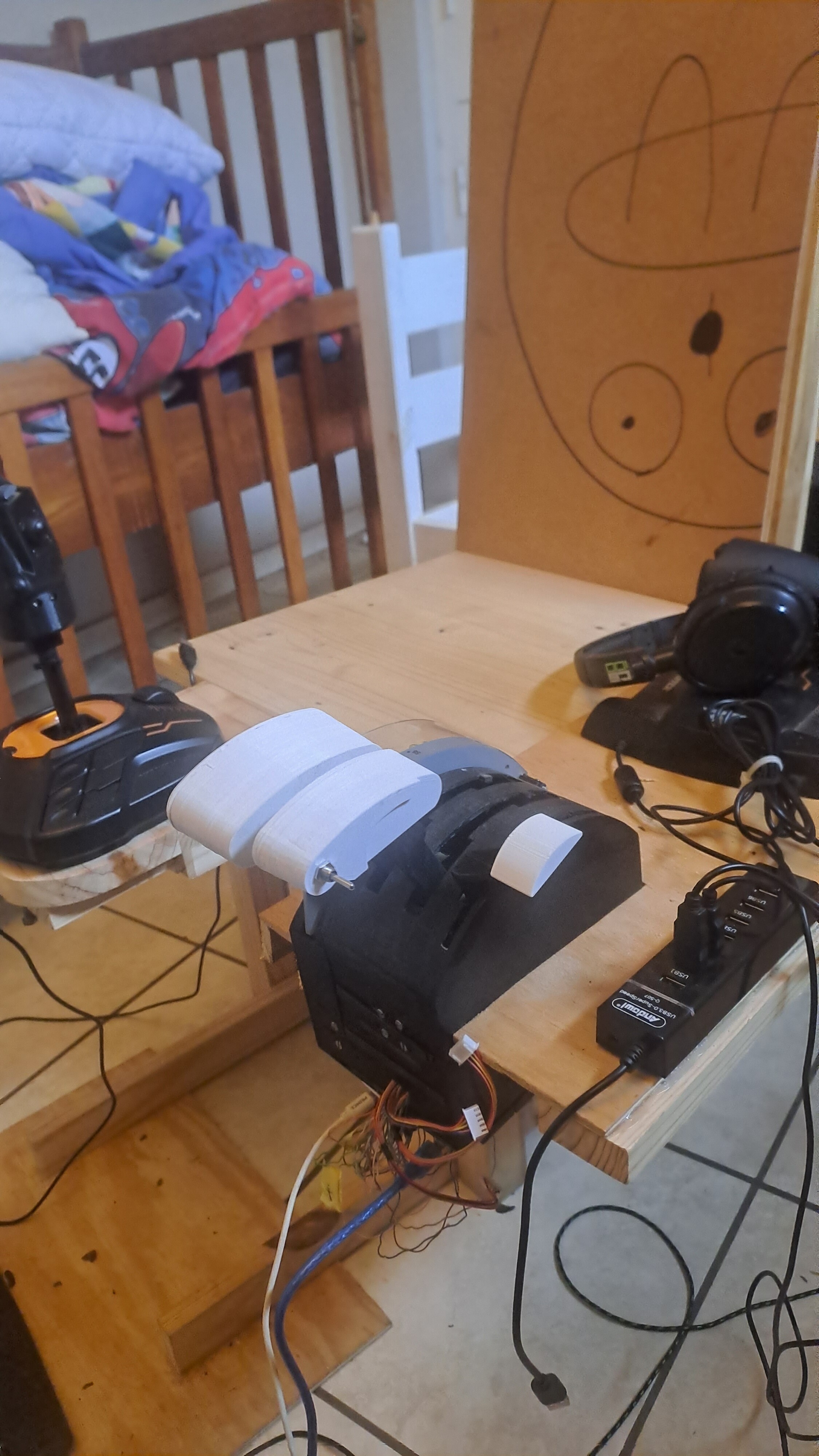
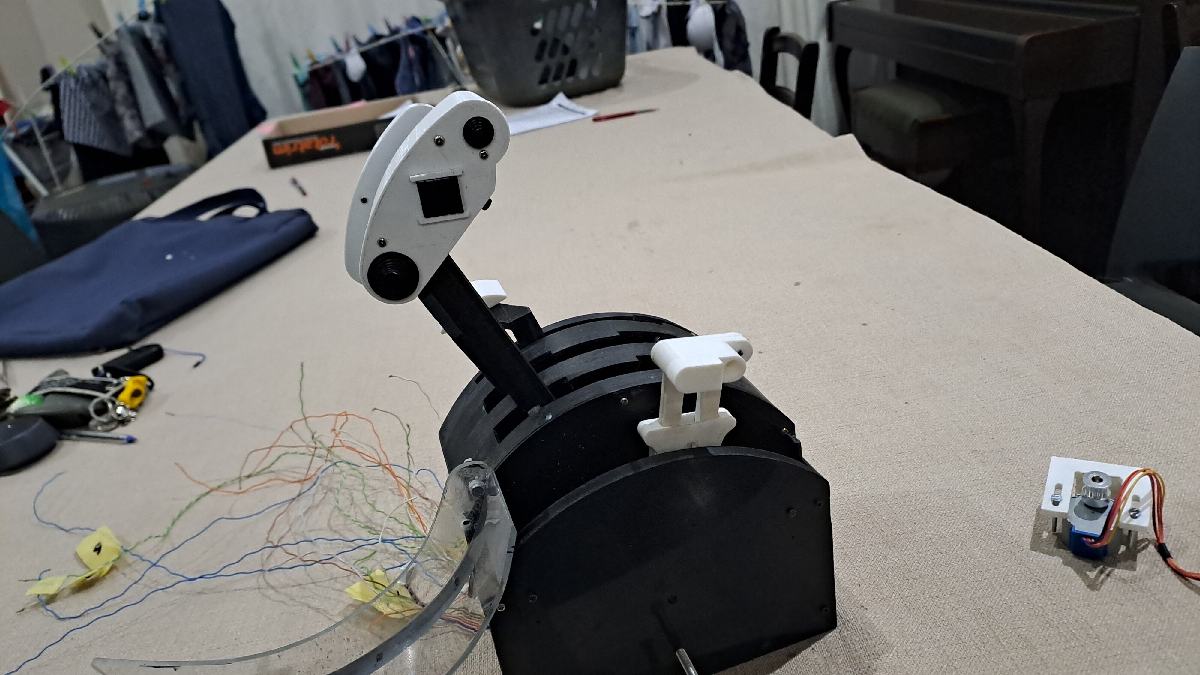
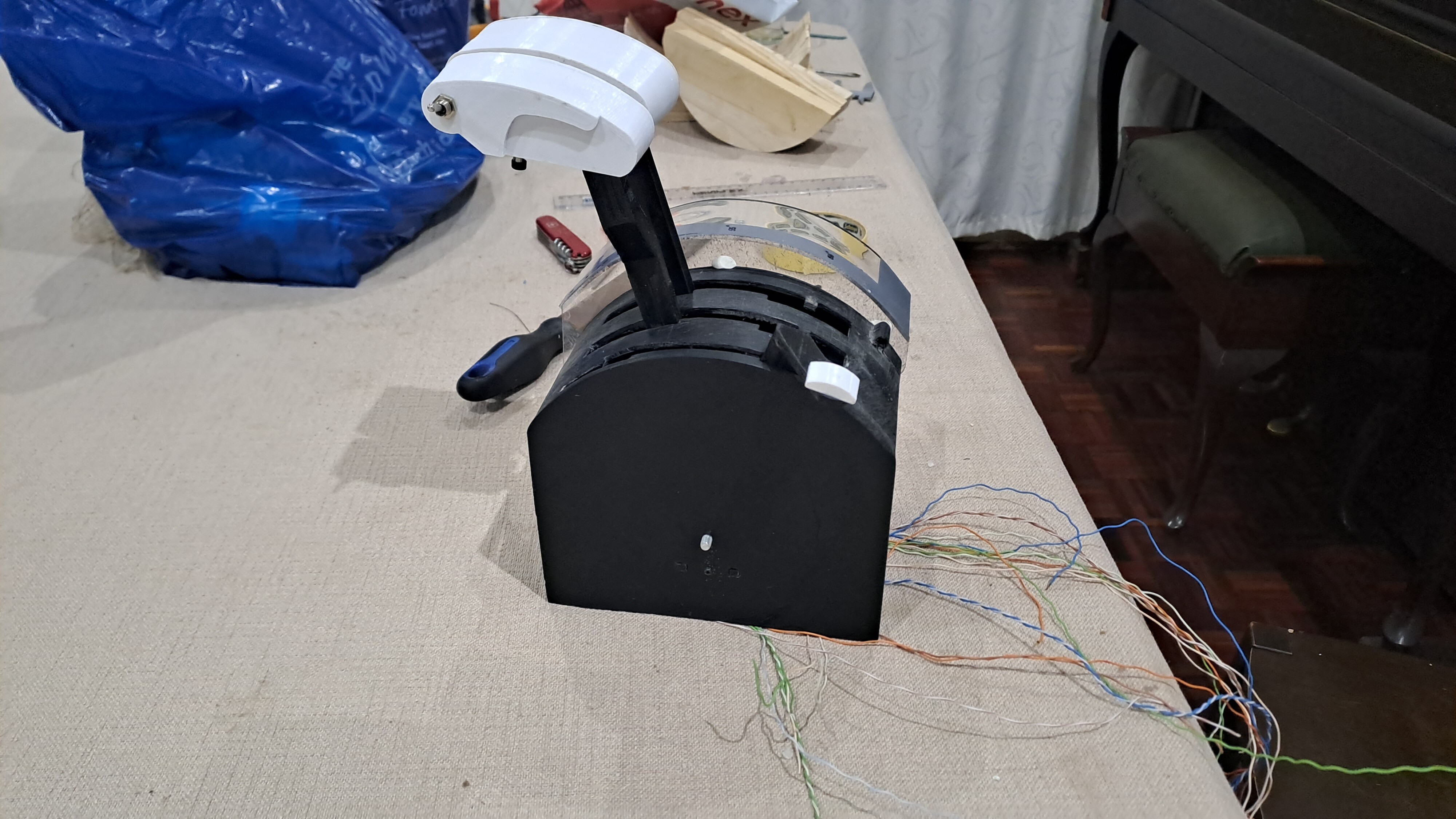
Time for another update - Been learning how to code arduinos. The problem that I had was that I don't have enough pins on one leonardo to operate all the buttons, axes and stepper motors. I tried and failed to use shift registers and I2C components. I could have tried a multiplexer, but in the end I just bough a pro-micro to handle the buttons - the Leonardo handles the axes and will also control the stepper motors. I was worried that DCS would confuse the two boards but that doesn't seem to be a problem. Now that the axes and buttons are working, with sufficient pins to add the stepper motors, I went and installed in my crude simpit chair. Pretty happy with how it has turned out. I ran out of room in the box itself to contain the leonardo and stepper motor boards, hence you can see them poking out the front. Nevertheless, as a simple axis with all the buttons in the right place, it works. It's pretty cool to open the wingsweep cover and see the same thing happen in DCS.

-
multiple arduinos conflicting
Gareth Barry replied to bessta's topic in Controller & Assignment Bugs
Apparently you have to rename one of them in the 'boards.txt' file as well as chanigng two other numbers. But this is not without risk of bricking the microcontroller. And to make matters worse, arduino updated the IDE so that changing the name as I mentioned above is not nearly as simple as it used to be. I don't know if you have had success with this? -
Hi all I'm hoping this is the correct place for this question- I am wanting to build my own throttle replica for the f14. I am at the point of coding and connection an arduino leonardo, and I would like to use to CD4021 shift registers daisy-chained together to handle the 15 buttons that I am going to need. I am having some trouble understanding the 'shiftin' function for arduino, and how to use it work with the joystick.h library in order to use the shift registers to handle the buttons. I have found this tutorial; CD4021B Shift Registers | Arduino Documentation I am still struggling to make sense of how I would modify it to handle the buttons of the joystick. Any help would be greatly appreciated.
-
**********update*********** sorry for the lack of progress, been a bit busy with work. Nevertheless, some progress has been made. All of the hardware side of things has now been hooked up and is functioning correctly, as far as I can tell. Funny how certain things that one thinks will be trivial end up being a hassle- namely, getting the magnetic field oriented correctly so that the Hall effect sensors will work properly. Got there in the end though. On the plus side, the wing sweep handle system that locks into the 4-degree notches is working perfectly. The next step is to get it working as a basic throttle, without the stepper motors moving anything- even though I have tested those on both throttles and the wing sweep-handle and they work perfectly. I have ordered an Arduino Leonardo and two CD4021B shift registers to get all the buttons to work. I'm still struggling to make sense of shift registers and the 'ShiftIn' library of Arduino - the basic joystick with the joystick.h library seems fairly simple.
-
I think what helps me is to hear "Slammer" Richardson's voice in my head telling me to be '2 steps ahead of the jet.' In this particular instance, for me that means working the throttles by small amounts, but constantly. I know that kinda contradicts what I said earlier, but at this stage in my 'flying' (250 hours in the 'cat) I have my hands full trying to manage lineup, ball and groove time and being consistent. I find that I land better after I've done some inflight refuelling, as it forces me to have finesse with the throttle, particularly in terms of being 'ahead' of it, ie accounting for the delay in perceptibe repsonse from whatever input i make from the throttle. Oh, and some interviews do mention small blips of DLC here and there. I know victory 205 says it's really just to counteract ballooning over the ramp, but I have heard other pilots talk about using in other parts of the pattern. In any case, I do try to keep it to a minimum. Personally, I found that a mistake i was making was not adding sufficient power prior to the final turn onto the groove - all because I didn't want to spoil my beautiful on-speed trim that I had worked to achieve on the downwind leg. This would result in my losing too much altitude during the final turn, then intercepting the glideslope too close to the boat, and with a hell of a lot of work to do to get properly trimmed when I finally did get the ball in the right place but with very little time left to keep it there. Far better to add some power in the final turn, manage the descent properly, to come out right smack bang where the needles cross on the TID, giving me sufficient time to trim for the groove onto (hopefully) a perfect 3 wire. Sorry if some of this if OT.
-
I've also wondered about this, particularly since I am building a set of f14 throttles that have functioning autothrottles- the NATOPS specifically says that autothrottle can be selected on the downwind leg before final 'if desired', thereby implying to me at least that it is perfectly valid to select autothrottle for even CASE 1 approaches. In that case, the way to get more power if you need it is to pull back on the stick, and vice versa. Having said that, listening to interviews with LSOs, they seem to imply that the only perfect landing is one which has zero corrections at all, not pitch, throttle, nada, but coming into a perfect 3 wire in around 17 seconds of groove time. In other words, the turn on to final approach is managed such that when the jet has rolled out, it is lined up perfectly laterally, at the correct altitude, on speed and with perfect sink rate, with zero subsequent corrections needed. Seems almost impossible to me, but there you go. Interviews also seem to suggest that it was all the more difficult with the tomcat to get good scores because the jet telegraphed any and all corrections to the LSO.
-
Thanks Yogi but honestly, your throttle is really on a whole different level, and if i was to go back in time, i reckon i would just print yours! However, i have learnt a heck of a lot in terms of electronics and coding, which i guess was really the point. My real hope is that i can get the autothrottle working and people can use that as an outline to do it for themselves if they so desire.
-
Also been working on the geometry of some of the parts, for example, the wing sweep cover is presently interfering with the wing sweep handle when in the overswept posiiton, so I have to fix that. On the whole though, some solid progress. From a coding point of view, I have been able to; 1. Get the stepper motors to work smoothly and reliably in both directions, whilst bein easy to override by hand 2. Managed to code a way by which manually moving the throttles forwards or backwards manually when the stepper motor is turning disengages the stepper motor and then returns the updated throttle position. The GT2 belt acting as a simple clutch is working very well. I still have to buy a leonardo and some PISO shift registers, and then figure out how ot make those work within the joystick library. I also have to get DCS BIOS to work, but I want to make sure all of the mechanicals are sorted first.
-
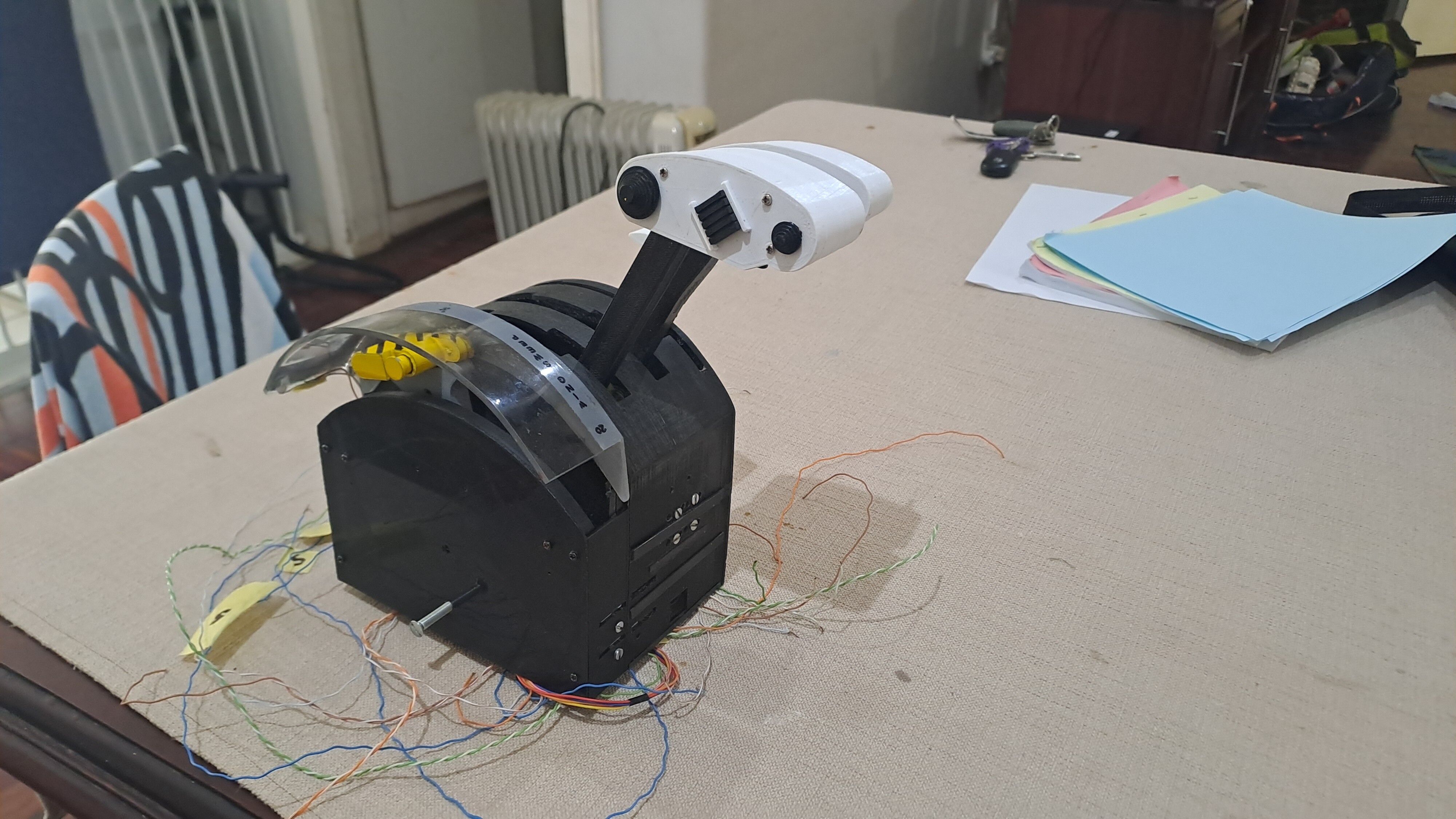
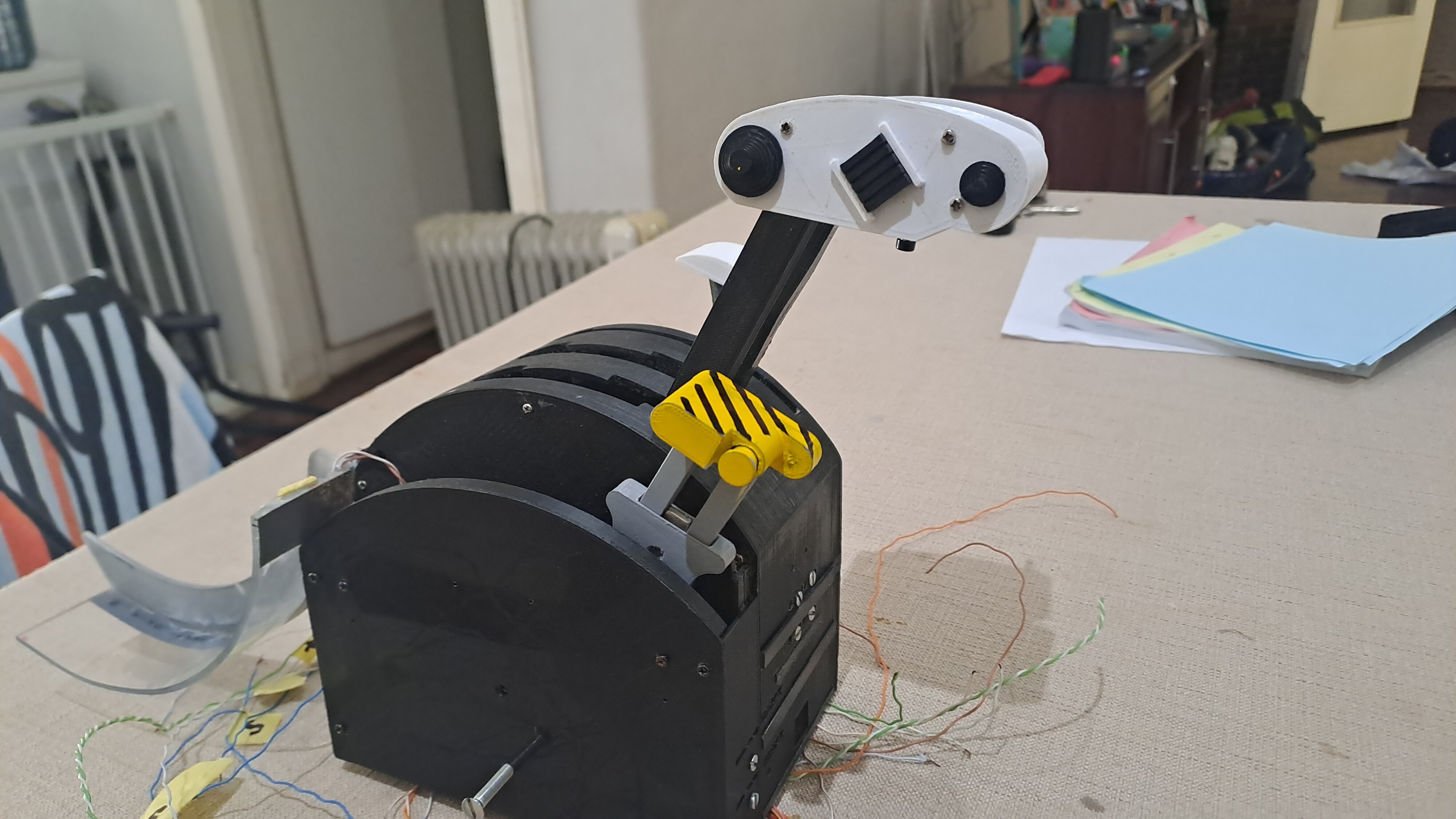
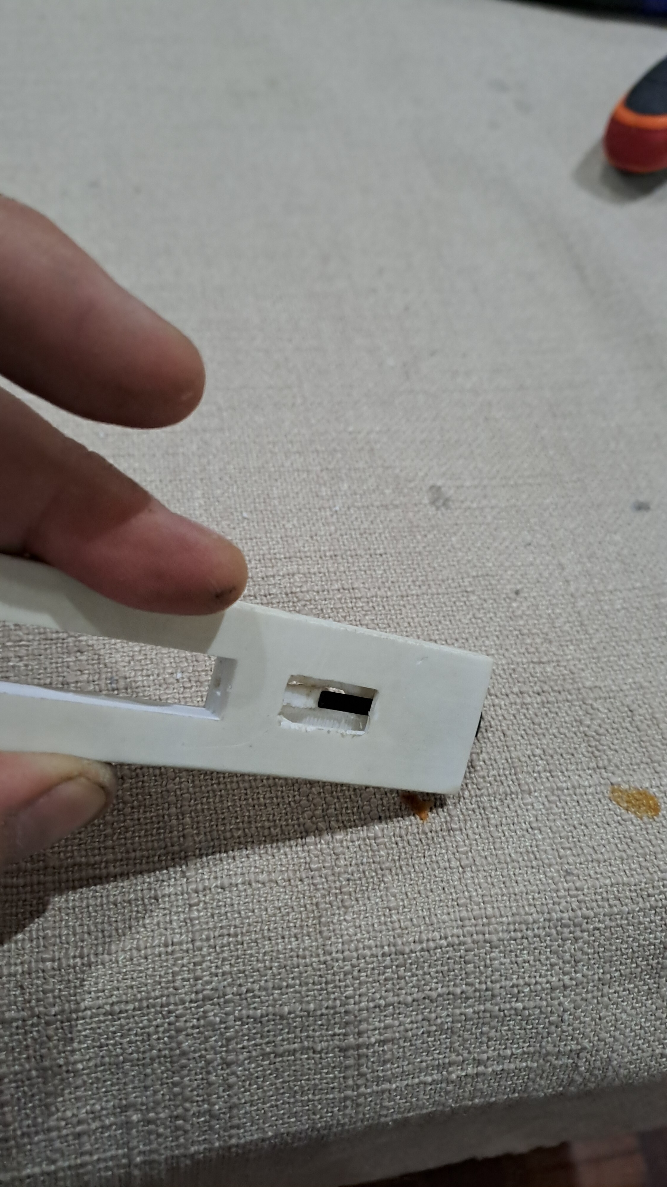
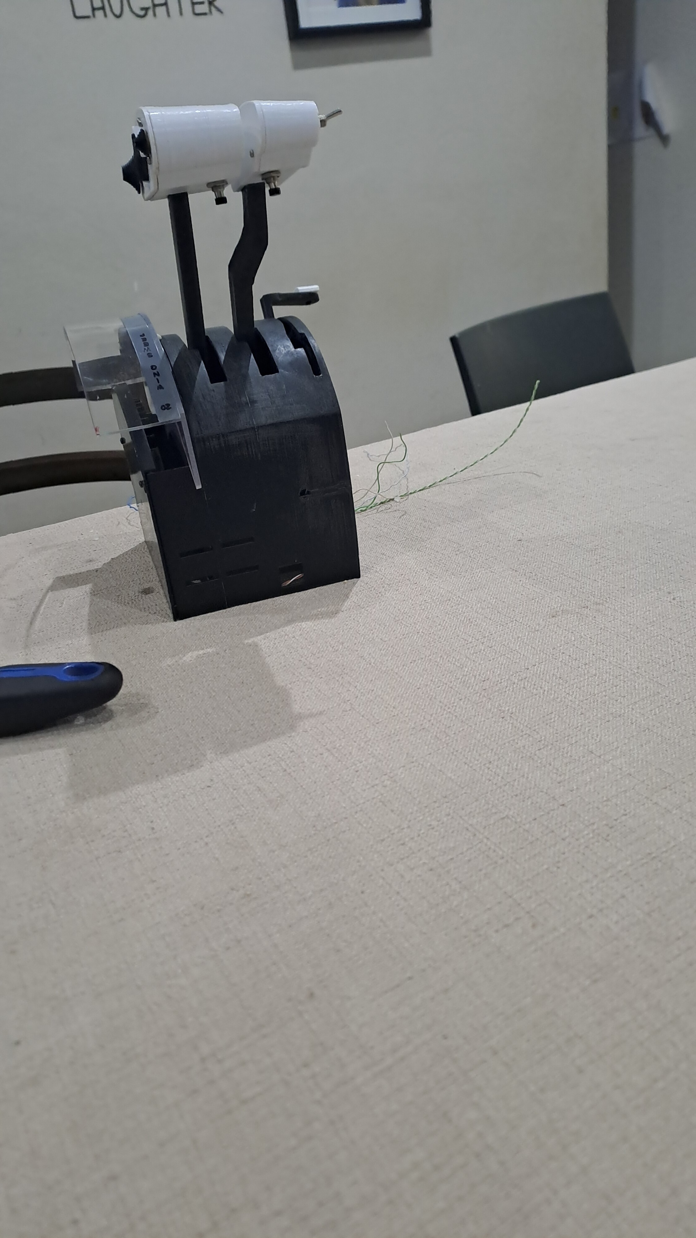
Some updates, got the wing sweep handle printed and functioning. To be honest, I was rather shocked at how well it works, especially given how little and fiddly the parts are. When the handle is extended, the little spring loaded latch flicks out and slots into the '4 degree notches.' I am using a thin strip of carbon fibre as the spring. The handle still has to be painted greay, with the yellow and black striping on the upper part of the handle. You can see in the above shot how the shape of the latch allows it to slip under the notches when being pulle dup, but not when being pushed down. In order to stow the handle once extended, it must be put into the 20 degree or overswept position. And here is a shot of the whole thing almost fully assembled, minus the stepper motor for the wing sweep handle, which is in its mount in the background.
-
Elo, thank you so much, this is extremely helpful. I will definitely go the flightpanels route.
-
Thanks Elo Perhaps you can clarify - my (mis?)understanding was that flightpanels is specific for interacting with saitec equipment? When I was looking through the DCS BIOS commands for the f14 I was very surprised to see that there is nothing for the throttle position on autopilot - so I was thinking of getting that indirectly from eg the engine rpm or fuel flow?
-
OK so, I managed to get far more torque from the stepper motor without having to mod the stepper motor itself, essentially from better coding. The speed of movement of the throttles is perfect, as is the ease at which they can be overridden by hand. Overall I am extremely pleased to this point, despite taking a whole day to figure out how to get the halll effect sensors to work properly and breaking 2 of them!! In the end it basically came down to needing a stronger magnetic field. So now I am at the point where I am trying to get to know DCS BIOS and I have hit an immediate roadblock - I can't even get it to open! My firewall (I think) seems to be blocking it - it won't let the program 'listen on tcp port 5010' or some such. I have tried unblocking it on the advanced settings, bo matter what I do I can't get it to work. Any ideas? Ok; I'm a dumbass...it was open on the bottom taskbar lol!!
-
please ignore, problem solved
-
Hi Rustbelt Your idea as you outline the general coding is essentially exactly how I was going to implement it. My idea was to use a leonardo instead of my current uno, as my understanding is that it's easier to implement it as a joystick. I thought of just using the uno and communicate the throttle position directly through DCS bios, but i like the joystick libraries such as unojoy, and I can at least then calibrate the thing easily. Obviously I would have to add lines of code in order to communicate with DCS Bios as well as get the autothrottle and wingsweep working. Having said that, I have no intention of making this a general use throttle for anything other than DCS with the Tomcat - I hardly ever play IL-2 and mastering the Tomcat is honestly taking up all my sim time. For steppers I am using the typical ULN2003 driver, and tried powering it with its own supply instead of through the arduino, which didn't seem to make much difference to the amount of torque produced. I preferred powering it with its own supply, less chance of blowing the USB on my PC. I have been some reading in terms of gaining more torque form these things (28 BYJ steppers), as I understand it, my options are; 1. run the whole thing at a higher voltage, and make sure that there is enough pause/time delay in the loop to let it cool down some between steps 2. run it as a bipolar stepper ommiting one of the wire taps, but that would require using a more expensive driver 3. Actually write out the code to send voltage to each tap(s) in sequence in order to step the motor, and in doing so, send 'high' to 2 taps at once during each step. This should increase the torque somewhat. Going to fiddle tonight and see. I feel that I am somewhat on the right track.
-
Hi Yogi Let me say that your stunning throttle helps provide motivation for me to finish mine! I have looked at your throttle extensively and stolen ideas here and there, so don't worry about sending me the files, i would have re-engineer the whole thing anyway to fit mine- i seriously appreciate the offer though! And you are right re the whole thing sliding around- I clamped it down firmly and the whole thing felt a heck of a lot sturdier. However, the problem I think is the 3d printed stalks, they seem to have some flex in them. I will need to increase the sturdiness of those I think. In terms of stiction, if I hadn't planned on going with functional autothrottles, I probably would have used the same system that is used on my dobsonian mounted telescope - ie a pair of teflon pads on a slightly 'pebbled' surface such as formica. And now, some progress electronically. I have been learning about dcs bios, but more so how to use arduino in general. I got the throttles moving backwards and forwards using the inbuilt stepper function in the arduino. The results were slightly disappointing, these steppers seem just barely adequate in terms of torque. Anyways, I will keep fiddling with the code, power supply, and perhaps go to the 9v versions of the same stepper motor. I also managed to figure out how to read in an analogue voltage and print out a serial number based on that. So the plan for now is to get to a system whereby I use both this throttle and the new one as a test - I will hook up DCS bios to give out the position of the throttles when in autothrottle, which will energise the stepper motors, which will start moving the levers on the new throttle, whilst the t16000m is stationary. From there I will try to combine both functions into one. Should have the main handle printed sometime this week.
-
Hi Yogi That's actually a good question- I made some mistakes on the chassis design; in particular, I didn't give enough wall thickness in places which has meant I needed to glue some reinforcements to stop the walls from bending due to the tension from the stepper motor belts. These are things I will correct when I publish the whole thing. On the whole, it is not as sturdy and rigid as my thrustmaster t16000m. Still acceptable though. On the plus side, I was pleasantly surprised of the feel of the belt sliding over the throttle stalks. The rubber gt2 belt over the plastic seems to have similar coefficient of static and dynamic friction, meaning that there is less 'stiction' than for example my t16000m. I find the 'stiction' on my thrustmaster to be somewhat of an annoyance when trying to get very fine control of the throttle, either on final approach or a2a refuelling. I know there are workarounds with niogel etc and i have tried these but it still not great. I compare it to for example my dobsionian telescope that I built, where the feel is utterly buttery smooth - this throttle approaches that. Making a start now on learning arduino. Will get the wing sweep handle printed next week.
-
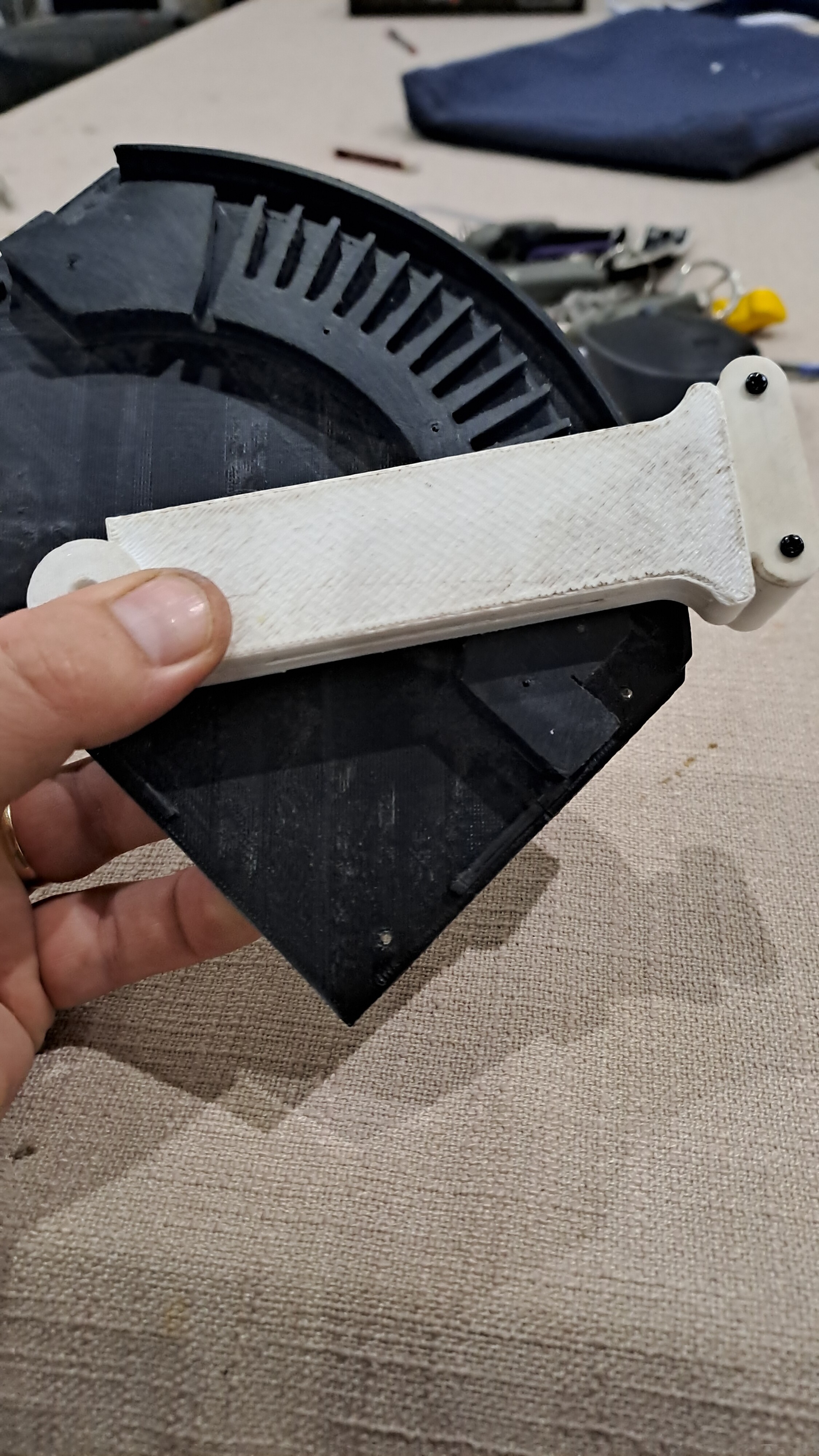
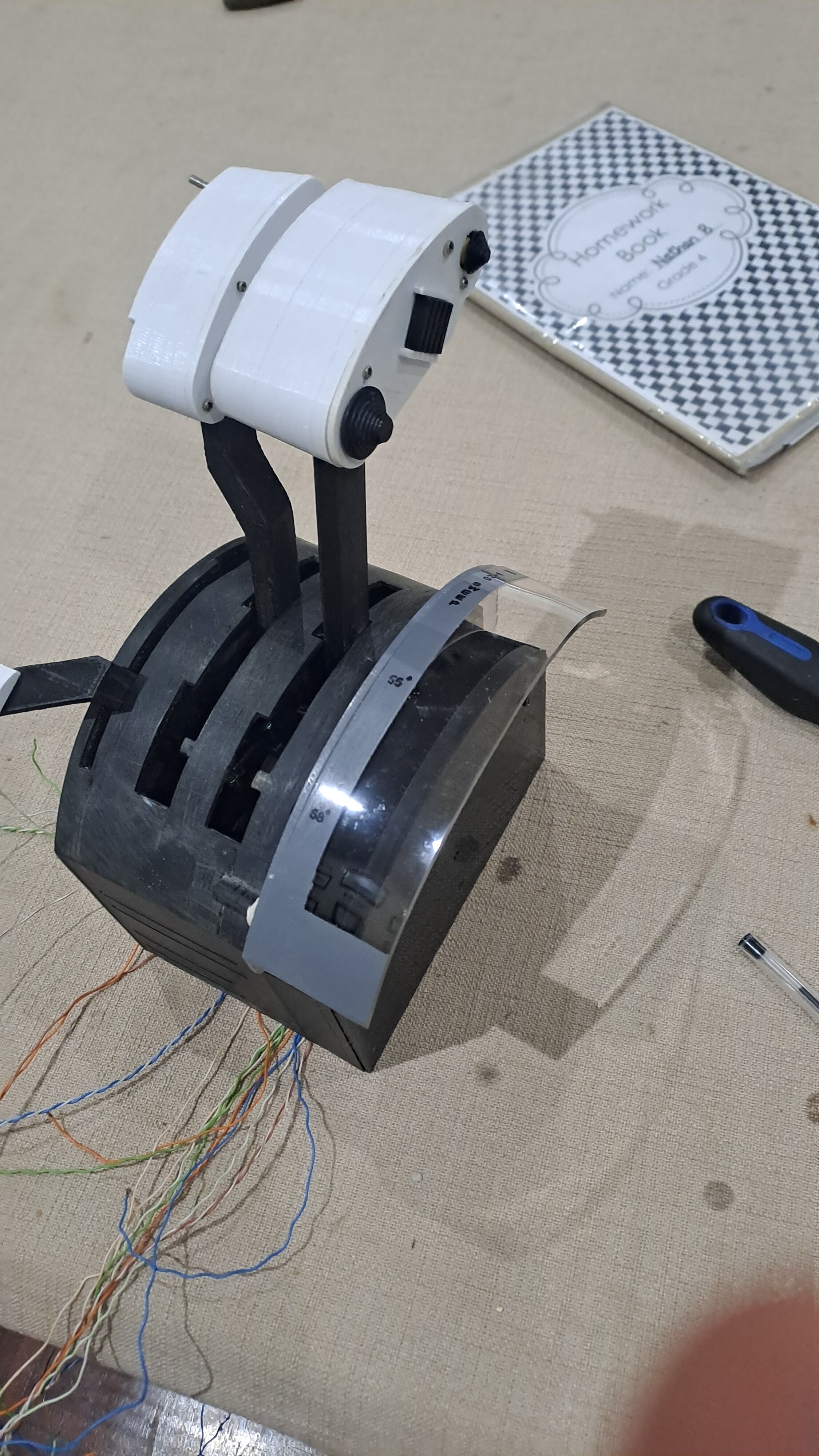
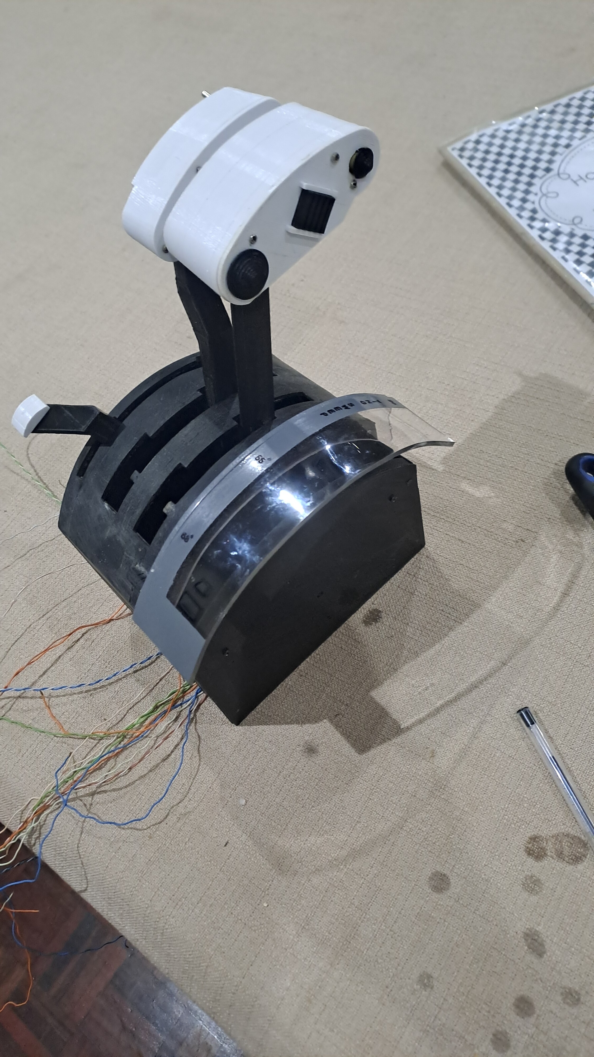
Here you can see how i basically manufactured it - I first laser cut and engraved the main section from 3 mm acrylic. I then made a set of form blocks to the same radius as the throttle chassis, then heated the acrylic with a heat gun and pressed it between the form blocks - a bit of spring back here was a good thing as the radius needs to be slightly more than that of the throttle chassis. You can see one half of the form block in the background of one of the pictures. Anyway, once that was done, I cut the flat section on the bandsaw and glued the two pieces together using MEK. works very well. Masked and then painted grey. There was a bit of overspray, but that will be easily cleaned up with some polishing. If you look at the last photo, I think it's still sitting a bit high relative to the rest of the throttle chassis, what do you guys think? I think I need to trim the bottom curve a touch to make it sit lower. I haven't drilled the hole for the swivel yet, it's just held on with prestick. I finish it up tomorrow. In the meantime I am going to get the stepper motors in place.
-
Thanks guys- that's I guess why i embarked on this project, ie to learn to fly the jet as close as possible to how it was IRL. i guess I mostly use full mil, min burner and full burner in combat, so the mil stops should help keep everything aligned. I guess it's just something one gets used to in multi-engined aircraft. So made some more progress today - most of the electronics have arrived, just have to do my final meaurements of the wing seep handle and then print that. I made a start on the wiwng sweep cover, was quite happy with the way it turned out. I discovered something called a 'mercury tilt switch,' which seems absolutely perfect for the wing sweep cover, so I ordered one and will be trying it out. Still going to use a reed switch for the handle extension.
-
And now I have some questions for people with dual throttles or perhaps someone with knowledge of how the actual tomcat throttles function can respond. My question is, is there any mechanical linkage between the two throttles to keep them moving together? I know that there there is the assymentric thrust limiter, but the NATOPS seems to imply that this is only for ensuring that both cans are lit at more or less the same time. It just seems somewhat disconcerting to me, coming from my t16000m throttle, so thrust assymetry isn't something I have had to deal with. The wide apart engines+thrust assymetry seems like a recipe for disaster (Maverick notwithstanding). I thought about perhaps linking the two via a magnet or something, such that they can be pulled apart if needed but that they usually 'stick' together- dunno if that makes sense or whether I am over thinking this.