overpro
-
Posts
158 -
Joined
-
Last visited
Content Type
Profiles
Forums
Events
Everything posted by overpro
-
According to my friends and my own statistics, we are always suffering these issues: 1. Unable to login to multiplayer, after entered username and password and click Login, it stuck at the login page. 2. unable to connect to master server. 3. Server Ping Timeout, it will always happens with no exception, some times it happens after 5 mins since I join the server, but some times it happens 30 mins or 1 hour later. If the server are located in mainland China it may even worse! I'm pretty sure that our network quality is the worst in the world, we have 3 major ISPs: China Unicome, China Telecom and China Mobile but the interconnection between them are terrible. This is how I found out: I have a TS server installed on my PC and by inspecting the connected peoples network statistics, I can see that the average packet lost is around 5%~15%. So if I setup a DCSW server and ask friends in China to join, there are 30% of the chances that they are even unable to see my server or they can't join the server connect by IP. If we connect to foreign servers, the situation might be a little bit better but the lag is worse ( > 300ms ). Well, as you may know, China gov has some very powerful devices dubbed "The Great Firewall - GFW", tailored to internet censorship, this may set another layer of complexity to the situation. Make the case worse. We have a bunch of people would like to have some fun on DCSW multiplayer every weekend but it always end up with frustrating on login to multiplayer or lost connection to the server, we have to use two hours to figure out which server is suitable for most of the people, and after we connected and ready to takeoff, someone suddenly lost connection: "Server ping timeout", or "master server connection lost" WHAT THE HECK(****)? If someone have the chance to visit China I'd recommend to have the try on multiplayer. I'm sure you will have the impulse to smash the keyboard or monitor. We have the DCS A-10C since 2010 and it's good in terms of single player, but multiplayer? NO, IT SUCKS, I can't feel it's improvement on the connection stability during the last 5 years. Every time the news letter said it is improved, we update but still suffer the same: connection lost ... connection lost ... connection lost Does ED really care about the multiplayer stability?
-
an Arduino USB HID controller, composite USB controller
overpro replied to overpro's topic in Home Cockpits
Please check the top post, there are some instructions on how to compile the firmware, if you want to change the name check Descriptors.c ProductString definition, and I think the PID value in DeviceDescriptor should also be changed. -
an Arduino USB HID controller, composite USB controller
overpro replied to overpro's topic in Home Cockpits
Well, please have a try on this the current analogRead is : joyReport.axis[ind] = map(analogRead(54+ind), 0, 1023, -32768,32767 ); try changed the code to joyReport.axis[ind] = analogRead(54+ind) << 6; -
an Arduino USB HID controller, composite USB controller
overpro replied to overpro's topic in Home Cockpits
This requires change the firmware code for atmega16u2, delete the all the descriptors related to Endpoint 2 Output, and this also lead to the joystick HID report data structure changes so the arduino code also need to be modified : comment out all the key scan code from Row8 to Row16. Wire all the unwanted analog input pin to ground. To generate a "pulse" for a toggle switch or button ( edge triggered instead of level triggered) the key scan code should work like this: 1. Scan the key value, 0 is on, 1 is off ( we have input pins set to Input with Pull Up ) 2. Compare the scan value with the previous round's value ( need some buffer to store the previous value ), if you want a pulse when you flip on the toggle then the truth table is like below. Note that the "prev" and "current" value is the key scan value ( 0 = on , 1 = off ) and the result is the value should be put into the HID report ( 1 = 0n, 0 = off ) prev current result 1(off) 0(on) 1 0 0 0 0 1 0 1 1 0 3. after the HID report data is assembled for this round refresh the prev key scan value with the current one. 4. BUUUUUUUUUUUUT not finished yet, this algorithm needs more code to deal with the delay, with the above algorithm the pulse width is totally depends on the time difference between 2 rounds of keyscan: if the 2 rounds of the keyscan is only 3ms then the pulse width is also 3ms, this width is not enough for some of the flight sims especially FSX. The delay code works like this, declare an array of buffer to store how many keyscan rounds elapsed since the start of the delay for each button. Say we want to delay a pulse for 30 rounds, then increase the counter by one in each round of the keyscan. Once the counter reaches 30, set the the "result" to 0 and clear the corresponding counter to 0. the delay is used for rotary encoders, you can see how it is implemented in arduino sketch. -
an Arduino USB HID controller, composite USB controller
overpro replied to overpro's topic in Home Cockpits
what tools are you using for testing the button / encoder ? If you are using the Windows joystick test window for this then that make sense because the window only shows first 32 buttons status, you can try using some other tools such as "Pointy's joystick test" -
Well the ILS power button mapping has changed, at before press the mapped button turn it on and press it again turn it off, now you need 2 buttons to do that: one button is for turning on, the other is for off.
-
an Arduino USB HID controller, composite USB controller
overpro replied to overpro's topic in Home Cockpits
Hi usul :wacko: i can't see any error in the wiring, have you tried remove the button and just keep the rotary encoder alone to see if it works? -
an Arduino USB HID controller, composite USB controller
overpro replied to overpro's topic in Home Cockpits
Uh, got it, just as Ian mentioned above, please refer to that link on how to configure the switches in DCSW -
an Arduino USB HID controller, composite USB controller
overpro replied to overpro's topic in Home Cockpits
The toggle switch works just like a push button, you flip on the switch then it's on, flip it to the off position then it's off. I don't quite understand on this: "I hook a toggle switch up to it and it flipped the switch on but I could turn the switch off" Are you saying after flip on the toggle switch you are unable to flip it back to the off position? I tested by using http://www.planetpointy.co.uk/joystick-test-application/ and never encountered this issue before. For the 3 pin toggle switch, you can just wire the common (middle) pin of the toggle switch to the ROW pin in the matrix board, and wire the left / right pin of the switch to the COLUMN pin. Can you please provide more details on this? -
an Arduino USB HID controller, composite USB controller
overpro replied to overpro's topic in Home Cockpits
Well I haven't tried to compile the firmware under windows, so a stable approach would be use Linux to compile the firmware, and we don't need to edit Makefile too much. I added a simple instructions on how to compile it under linux, actually It's very easy. please check the first post of this thread. If you prefer windows anyway, then I believe GNU make ( MinGW make.exe or cygwin ) and GCC for windows is required. And winavr from sourceforge.com is required as well. -
an Arduino USB HID controller, composite USB controller
overpro replied to overpro's topic in Home Cockpits
Hi Peter, If you don't mind to have an ubuntu linux VM installed I can let you know how to compile the firmware, so you can change the name to what ever you want. Regards -
an Arduino USB HID controller, composite USB controller
overpro replied to overpro's topic in Home Cockpits
Hi banillasky, the code has the analogread() commented out in the arduino code ( it's located at the very end of the code ), you can uncomment the line and it should work. Please read the first few posts in this thread, there are some discussions. Uno R3 uses ATMega16U2 so the USB firmware can be used, but the arduino code can't be used on Uno, it requires some changes -
[opensource] A-10c EMI gauge with arduino and PCB KiCad file...
overpro replied to overpro's topic in Home Cockpits
:pilotfly: Good to see :) -
an Arduino USB HID controller, composite USB controller
overpro replied to overpro's topic in Home Cockpits
Hi Peter, many thanks for your effort on testing this, I think I have understand the point and uploaded the code to github, The arduino code was changed, no firmware change for ATMega16u2. please have a try when you are free. https://github.com/calltherain/ArduinoUSBJoystick/commit/0f7146c27b83f465fafaaf6b1d35ad45ab0cb2b1 -
an Arduino USB HID controller, composite USB controller
overpro replied to overpro's topic in Home Cockpits
Hi Peter, Thanks for the information, Regarding the pulse send to windows, actually the encoder's pulse is not send to Windows directly, instead, arduino main chip - ATMEGA2560 will try the best to capture the pulse from encoder and do some sanitization to judge a CW /CCW rotate, once a valid CW / CCW rotate is recognized the arduino board will send the USB report to Windows, so the pulse length has nothing to do with the USB report, I believe the code still missed some pulses generated from encoder. Anyway, let me have some try to see if I can make some improvements on this. I will PM you with my updated code. -
[opensource] A-10c EMI gauge with arduino and PCB KiCad file...
overpro replied to overpro's topic in Home Cockpits
Hi Marick, Below is the screen shot of the PCB view, connect your 5v power source to CONN 2 pin and be aware of the +(VCC) -(GND). For the CONN 3, connect CONN3-SER, SRCLK, RCLK to Arduino 22,23,24 or 25,26,27 or 28,29,30. Because one board controls 4 stepper motor, so 3 of this board can control 12 stepper motor which covers EMI panel. You can also attach just one board with one stepper motor to test your build. The CONN4 should be connect to stepper motor, if you are using the VID29xx or similar motor, the connection should be like this: I will post some pictures later to indicate the relationships between the 4 conn4 pins and the EMI gauges. Regarding the fp-lib-table.for-github, because I'm using the latest nightly build of KiCad, the project management is quite different compared to the downloaded Windows build which was released in 2013 July, I recommend you compile the KiCad by using KiCad-Winbuilder: https://launchpad.net/kicad-winbuilder
-
[opensource] A-10c EMI gauge with arduino and PCB KiCad file...
overpro replied to overpro's topic in Home Cockpits
Sorry I didn't check the files carefully, now I have fixed the Kicad CvPCB symbol to footprint associations. Please pull the files from github again, and make sure you add the default symbol footprint libraries by using this method: 1. copy this file d:\kicad-winbuilder-3.4\kicad\share\template\fp-lib-table.for-github to this place, ( remove ".for-github" from the file name ) %userprofile%\appdata\roaming\kicad\fp-lib-table 2. restart KiCad, and open Schema file and open CvPCB, this may take a few seconds because CvPCB will go to github to download the footprint libraries. And you should good to go. Please let me know if it works or not. ps: I also uploaded the gerber files to github, just in case anyone who wants to have a try ASAP. -
[opensource] A-10c EMI gauge with arduino and PCB KiCad file...
overpro replied to overpro's topic in Home Cockpits
Not really, I just made one PCB by myself, it's ugly :(, but you might want to try my shared my PCB designs on first post, it's KiCAD files. You can use KiCAD to export the PCB to Gerber files and send them to a PCB manufactures to build some sample boards. Oh ... I didn't noticed that there are more then one models available, Just checked my shield and the chip model is WIZnet W5100. -
[opensource] A-10c EMI gauge with arduino and PCB KiCad file...
overpro replied to overpro's topic in Home Cockpits
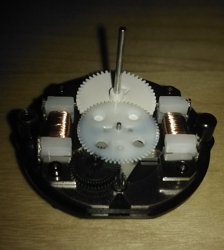
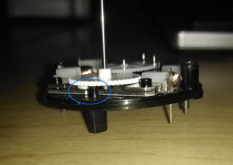
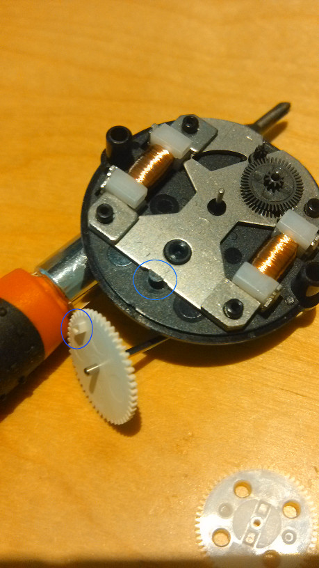
That's correct, I attached some pics of this motor, there is an internal block to make it hard stop. Because it's designed for gauges so the torque is small and will not make any damage. And if you cut one or both of the blocks and polish it carefully the gauge pointer can go 360 degree full motion but in that case you might need to add some photoreflectors to detect the zero position. a pair (Black and White ) of internal blocks:
-
[opensource] A-10c EMI gauge with arduino and PCB KiCad file...
overpro replied to overpro's topic in Home Cockpits
this stepper motor is tailored for gauge and has an internal block to limit the pointer to [0,315] degree, so no need to sense the zero position, just do a full range move is okay void GotoZero() { for( int i = 0; i < 315 * 12; i++) { sendCmdTo595_1( B00000000 ); sendCmdTo595_2( B00000000 ); sendCmdTo595_3( B00000000 ); sendCmdTo595_1( B01010101 ); sendCmdTo595_2( B01010101 ); sendCmdTo595_3( B01010101 ); delayMicroseconds(180); } } -
[opensource] A-10c EMI gauge with arduino and PCB KiCad file...
overpro replied to overpro's topic in Home Cockpits
occupied by myself for more information -
Some people might have the interesting to implement their own EMI gauges, I did one in last year, I'm glad to share the source code and the PCB design. This is the demo thread: http://forums.eagle.ru/showthread.php?t=115997 First of the first, I'm just a web developer, and have very limited experience on MCU, PCB deisgn, so my work is not beautiful, don't argue me on that :joystick: License: The MIT License (MIT) export.lua: function LuaExportStart() udpEMI = socket.udp() udpEMI:setpeername( "192.168.1.105", 13135) //change the IP and port according to your env udpEMI:settimeout(0) end function LuaExportActivityNextEvent(t) --get the value of each EMI gauge and multiply a number, --the result is the required stepper motor's position, the driver IC is VID6606 --and stepper motor is VID29xx it's one step equals 1/12 degree if driven by VID6606, --for example, apu_temp gauge, it's maximum degree is 3120 / 12 = 260 degree. --the factor 3120 is just a estimated number, looking at the EMI gauge panel --it seems that the APU_TEMP 's pointer range is [0, 260] degree local mainPanel = GetDevice(0) udpEMI:send( string.format([[%c %.0f %.0f %.0f %.0f %.0f %.0f %.0f %.0f %.0f %.0f %.0f %.0f]], 1, mainPanel:get_argument_value(14) * 3120 , --apu_temp mainPanel:get_argument_value(13) * 2880 , --apu_rpm mainPanel:get_argument_value(83) * 3240 , --engOilPressureRight mainPanel:get_argument_value(82) * 3240, --engOilPressureLeft mainPanel:get_argument_value(85) * 3600, --engFuelFlowRight mainPanel:get_argument_value(84) * 3600, --engFuelFlowLeft mainPanel:get_argument_value(80) * 3240, --engCoreSpeedRight mainPanel:get_argument_value(78) * 3240, --engCoreSpeedLeft mainPanel:get_argument_value(77) * 3780 , --engFSIRight mainPanel:get_argument_value(76) * 3780 , --engFSILeft mainPanel:get_argument_value(73) * 3120, --engITTTenthRight mainPanel:get_argument_value(70) * 3120 --engITTTenthLeft )) arduino code is available on my github repo: https://github.com/calltherain/Arduino_DCSW_A10C_EMI detailed spec of VID6606 and VID29xx stepper motor: http://www.vidmotion.com/product.aspx?sortid=24 http://www.vidmotion.com/product.aspx?sortid=22 The PCB Schema and Boards files are here , It's KiCAD files: https://github.com/calltherain/VID6606_595 ps: I really love KiCAD, it's easy to learn and good enough, I'm using the binaries compiled by myself, you can download the source code and build it from here: https://launchpad.net/kicad-winbuilder
-
an Arduino USB HID controller, composite USB controller
overpro replied to overpro's topic in Home Cockpits
good, will do -
an Arduino USB HID controller, composite USB controller
overpro replied to overpro's topic in Home Cockpits
Hi azreark1, are you using the Microsoft Windows joystick configurator to check the button status? It can only shows first 32 buttons of the joystick, you can check the button in DCSW or Xplane or SVMapper(http://forum.sukhoi.ru/attachment.php?attachmentid=70479&d=1173468799) -
an Arduino USB HID controller, composite USB controller
overpro replied to overpro's topic in Home Cockpits
I'm thinking if the poti connection is correct, the outer pins should connect to the 5v and ground repectively, and the 3rd pin should connect to the analog pin 1~8, please refer to this page: http://arduino.cc/en/Tutorial/AnalogReadSerial

-productD__projects_kiCad_vid6606_595_Newfolde.png.20073952d83f1d0468276f923cbde003.png)